EP1227655A2 - Image reading apparatus - Google Patents
Image reading apparatus Download PDFInfo
- Publication number
- EP1227655A2 EP1227655A2 EP02001378A EP02001378A EP1227655A2 EP 1227655 A2 EP1227655 A2 EP 1227655A2 EP 02001378 A EP02001378 A EP 02001378A EP 02001378 A EP02001378 A EP 02001378A EP 1227655 A2 EP1227655 A2 EP 1227655A2
- Authority
- EP
- European Patent Office
- Prior art keywords
- original
- image reading
- image sensor
- contact type
- type image
- Prior art date
- Legal status (The legal status is an assumption and is not a legal conclusion. Google has not performed a legal analysis and makes no representation as to the accuracy of the status listed.)
- Granted
Links
Images







Classifications
-
- H—ELECTRICITY
- H04—ELECTRIC COMMUNICATION TECHNIQUE
- H04N—PICTORIAL COMMUNICATION, e.g. TELEVISION
- H04N1/00—Scanning, transmission or reproduction of documents or the like, e.g. facsimile transmission; Details thereof
- H04N1/04—Scanning arrangements, i.e. arrangements for the displacement of active reading or reproducing elements relative to the original or reproducing medium, or vice versa
- H04N1/10—Scanning arrangements, i.e. arrangements for the displacement of active reading or reproducing elements relative to the original or reproducing medium, or vice versa using flat picture-bearing surfaces
- H04N1/1013—Scanning arrangements, i.e. arrangements for the displacement of active reading or reproducing elements relative to the original or reproducing medium, or vice versa using flat picture-bearing surfaces with sub-scanning by translatory movement of at least a part of the main-scanning components
- H04N1/1026—Scanning arrangements, i.e. arrangements for the displacement of active reading or reproducing elements relative to the original or reproducing medium, or vice versa using flat picture-bearing surfaces with sub-scanning by translatory movement of at least a part of the main-scanning components using a belt or cable
-
- H—ELECTRICITY
- H04—ELECTRIC COMMUNICATION TECHNIQUE
- H04N—PICTORIAL COMMUNICATION, e.g. TELEVISION
- H04N1/00—Scanning, transmission or reproduction of documents or the like, e.g. facsimile transmission; Details thereof
- H04N1/04—Scanning arrangements, i.e. arrangements for the displacement of active reading or reproducing elements relative to the original or reproducing medium, or vice versa
- H04N1/10—Scanning arrangements, i.e. arrangements for the displacement of active reading or reproducing elements relative to the original or reproducing medium, or vice versa using flat picture-bearing surfaces
- H04N1/1013—Scanning arrangements, i.e. arrangements for the displacement of active reading or reproducing elements relative to the original or reproducing medium, or vice versa using flat picture-bearing surfaces with sub-scanning by translatory movement of at least a part of the main-scanning components
- H04N1/1017—Scanning arrangements, i.e. arrangements for the displacement of active reading or reproducing elements relative to the original or reproducing medium, or vice versa using flat picture-bearing surfaces with sub-scanning by translatory movement of at least a part of the main-scanning components the main-scanning components remaining positionally invariant with respect to one another in the sub-scanning direction
-
- H—ELECTRICITY
- H04—ELECTRIC COMMUNICATION TECHNIQUE
- H04N—PICTORIAL COMMUNICATION, e.g. TELEVISION
- H04N1/00—Scanning, transmission or reproduction of documents or the like, e.g. facsimile transmission; Details thereof
- H04N1/04—Scanning arrangements, i.e. arrangements for the displacement of active reading or reproducing elements relative to the original or reproducing medium, or vice versa
- H04N1/10—Scanning arrangements, i.e. arrangements for the displacement of active reading or reproducing elements relative to the original or reproducing medium, or vice versa using flat picture-bearing surfaces
- H04N1/1013—Scanning arrangements, i.e. arrangements for the displacement of active reading or reproducing elements relative to the original or reproducing medium, or vice versa using flat picture-bearing surfaces with sub-scanning by translatory movement of at least a part of the main-scanning components
- H04N1/1039—Movement of the main scanning components
- H04N1/1043—Movement of the main scanning components of a sensor array
-
- H—ELECTRICITY
- H04—ELECTRIC COMMUNICATION TECHNIQUE
- H04N—PICTORIAL COMMUNICATION, e.g. TELEVISION
- H04N1/00—Scanning, transmission or reproduction of documents or the like, e.g. facsimile transmission; Details thereof
- H04N1/04—Scanning arrangements, i.e. arrangements for the displacement of active reading or reproducing elements relative to the original or reproducing medium, or vice versa
- H04N1/10—Scanning arrangements, i.e. arrangements for the displacement of active reading or reproducing elements relative to the original or reproducing medium, or vice versa using flat picture-bearing surfaces
- H04N1/1013—Scanning arrangements, i.e. arrangements for the displacement of active reading or reproducing elements relative to the original or reproducing medium, or vice versa using flat picture-bearing surfaces with sub-scanning by translatory movement of at least a part of the main-scanning components
- H04N1/1039—Movement of the main scanning components
- H04N1/1048—Movement of the main scanning components of a lens or lens arrangement
-
- H—ELECTRICITY
- H04—ELECTRIC COMMUNICATION TECHNIQUE
- H04N—PICTORIAL COMMUNICATION, e.g. TELEVISION
- H04N1/00—Scanning, transmission or reproduction of documents or the like, e.g. facsimile transmission; Details thereof
- H04N1/04—Scanning arrangements, i.e. arrangements for the displacement of active reading or reproducing elements relative to the original or reproducing medium, or vice versa
- H04N1/12—Scanning arrangements, i.e. arrangements for the displacement of active reading or reproducing elements relative to the original or reproducing medium, or vice versa using the sheet-feed movement or the medium-advance or the drum-rotation movement as the slow scanning component, e.g. arrangements for the main-scanning
-
- H—ELECTRICITY
- H04—ELECTRIC COMMUNICATION TECHNIQUE
- H04N—PICTORIAL COMMUNICATION, e.g. TELEVISION
- H04N1/00—Scanning, transmission or reproduction of documents or the like, e.g. facsimile transmission; Details thereof
- H04N1/04—Scanning arrangements, i.e. arrangements for the displacement of active reading or reproducing elements relative to the original or reproducing medium, or vice versa
- H04N1/0464—Scanning arrangements, i.e. arrangements for the displacement of active reading or reproducing elements relative to the original or reproducing medium, or vice versa capable of performing non-simultaneous scanning at more than one scanning station
-
- H—ELECTRICITY
- H04—ELECTRIC COMMUNICATION TECHNIQUE
- H04N—PICTORIAL COMMUNICATION, e.g. TELEVISION
- H04N1/00—Scanning, transmission or reproduction of documents or the like, e.g. facsimile transmission; Details thereof
- H04N1/04—Scanning arrangements, i.e. arrangements for the displacement of active reading or reproducing elements relative to the original or reproducing medium, or vice versa
- H04N1/19—Scanning arrangements, i.e. arrangements for the displacement of active reading or reproducing elements relative to the original or reproducing medium, or vice versa using multi-element arrays
- H04N1/191—Scanning arrangements, i.e. arrangements for the displacement of active reading or reproducing elements relative to the original or reproducing medium, or vice versa using multi-element arrays the array comprising a one-dimensional [1D] array
- H04N1/192—Simultaneously or substantially simultaneously scanning picture elements on one main scanning line
- H04N1/193—Simultaneously or substantially simultaneously scanning picture elements on one main scanning line using electrically scanned linear arrays, e.g. linear CCD arrays
-
- H—ELECTRICITY
- H04—ELECTRIC COMMUNICATION TECHNIQUE
- H04N—PICTORIAL COMMUNICATION, e.g. TELEVISION
- H04N2201/00—Indexing scheme relating to scanning, transmission or reproduction of documents or the like, and to details thereof
- H04N2201/04—Scanning arrangements
- H04N2201/0402—Arrangements not specific to a particular one of the scanning methods covered by groups H04N1/04 - H04N1/207
- H04N2201/0456—Arrangements not specific to a particular one of the scanning methods covered by groups H04N1/04 - H04N1/207 for maintaining a predetermined distance between the scanning elements and the picture-bearing surface
Definitions
- an image reading apparatus such as the one described above is provided with an image reading unit comprising a contact type image sensor (CIS) 1.
- the contact type image sensor 1 is placed in contact with an original placement glass platen and reads an original. It is placed under the original placement glass platen 2.
- the contact type image sensor 1 is mounted on a carriage 5, which is movable along a guiding shaft 4. More specifically, the contact type image sensor 1 is attached to an arm 6 which is rotationally supported by the carriage 5, with the interposition of a rotational axle 61, so that the image sensor 1 can be rotated about the axle 61.
- the contact type image sensor 1 is kept pressed upon the original placement glass platen 2, by a spring 7, with the interposition of a spacer 8 between the contact type image sensor 1 and original placement glass platen 2. Therefore, the spacer 8 remains in contact with the bottom surface of the original placement glass platen 2, maintaining a predetermined distance between the original placement glass platen 2 and contact type image sensor 1.
- the contact type image sensor 1 is provided with an LED 10 as a light source, and a light guiding member 11 for guiding light from the LED 10 to an original.
- the LED 10 is fixed to one of the lengthwise ends of the light guiding member 11, so that as the light emitted from the LED 10 advances through the light guiding member 11, while being repeatedly reflected by the interface between the light guiding member 11 and the ambience, the light is projected upon the original from across the entire lengthwise range of the light guiding member 11.
- the contact type image sensor 1 when reading a stationary original, the contact type image sensor 1 must be kept within the range of the original placement glass platen 2 to be moved relative to the original placement glass platen 2 in a manner to scan the original, whereas when reading an original by moving the original, the contact type image sensor 1 must be kept stationary relative to the second original placement glass platen 2a.
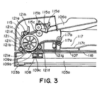
- a referential code 114 designates a cartridge cover, which is opened to expose the interior of the image forming apparatus main assembly 111 in order to mount or replace a cartridge in which a photoconductive drum or the like components are contained.
- a referential code 115 designates an ADF cover, which is opened to expose the sheet conveyance path in the ADF.
- a referential code 116 designates an original discharge path through which an original is conveyed to be discharged when reading the original while moving the original.
- a referential code 117 designates an original recovery tray into which an original is discharged when reading the original while moving the original.
- a referential code 118 designates a plate for holding down a plurality of bound originals in order to read one of them.
- the jump step 109b is given the function of a guide for guiding the original D2 away from the glass platen 109 when the original is moved to be read by the contact type image sensor 108 in the stationary state, and also the function of a stay for supporting the original placement glass platens 107 and 109.
- the spacers 108a are in contact with the bottom surface of the original placement glass platen 107 or 109, respectively.
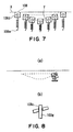
- the placement of the guided member 108d at the location at which the guided member 108d can realize the above described balance between the leading and trailing halves of the contact type image sensor 108 makes it possible to keep the contact type image sensor 108 stable to present the optical axis of the contact type image sensor 108 from tilting (tilting of the optical axis results in a blurred image).
- the reason for the provision of the above described positional relationship is as follows.
- the guided member 108d is subjected to the reactive force resulting from the pressure from the pressure generating means, or the spring, as it slides on the bottom surface of the contact type image sensor displacement guide 130.
- the positional relationship between the contact type image sensor 108, guided member 108d, and spring is designed so that there will be a distance between the point of the contact type image sensor 108, to which the pressure from the pressure generating means converges, and the point of the contact type image sensor 108, to which the guided member 108d is attached, in terms of the direction in which the contact type image sensor 108 is moved, the pressure from the pressure generating means, or the spring, acts to rotate the contact type image sensor 108 about the axial line of the guided member 108d; rotational moment is generated in the contact type image sensor 108.
- the pressure applied to the contact type image sensor 108 from the pressure generating means in order to keep the contact type image sensor 108 in contact with the original placement glass platen 107 or 109 acts to generate moment in the contact type image sensor 108, destabilizing the behavior of the contact type image sensor 108.
- the guided member 108d is disposed close to the point of the contact type image sensor 108, to which the pressure from the pressure generating means converges.
- This structural arrangement reduces the vibrations which occur when the spacer 108a of the contact type image sensor 108 comes into contact with the bottom surface of the original placement glass platen 107 or 109, making it possible for the contact type image sensor 108 to be smoothly displaced downward from the original placement glass platen 107 or 109, and placed back in contact with the original placement glass platen 109 or 107, respectively.
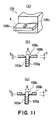
- Figure 11 is a schematic drawing for showing the measurements and configurations of two types of through holes 108c.
- Figure 11(a) is a perspective view of the portion of the contact type image sensor 108 adjacent to the through hole 108c
- Figure 11(b) is a sectional view of the contact type image sensor 108 at a plane A in Figure 11(a).
- Figure 11(c) is a sectional view of a contact type image sensor different in the configuration of the through hole from the one in Figure 11(b), at a plane A in Figure 11(a).
- the boss 103g was afforded more latitude in its tilting movement relative to the protrusion 108b in the direction indicated by an arrow mark Q in the drawing. Therefore, the amount of the scratching which occurs between the wall of the through hole 108c and boss 103g is reduced, making it possible to smoothly displace downward the contact type image sensor 108 from the original placement glass platen 107 or 109, and placed back in contact with the original placement glass platen 109 or 107, respectively.
- the jump step 109b has only to be provided with the function as a guide for guiding an original in the form of a sheet, and the function as a stay.
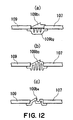
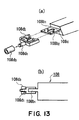
- Figure 13 is a schematic drawing for showing a concrete example of the guided member 108d, (a) and (b) being perspective and sectional views, respectively.
- the guided member 108d is attached to the protrusion 108b1 in a manner to sandwich the protrusion 108b1 with the top and bottom sides of the snap fitting portion 108d2. Therefore, the guide member 108d does not become loose relative to the protrusion 108b1.
Landscapes
- Engineering & Computer Science (AREA)
- Multimedia (AREA)
- Signal Processing (AREA)
- Facsimile Scanning Arrangements (AREA)
- Facsimiles In General (AREA)
Abstract
Description
It can be moved to any point within its movable range by a driving
Therefore, the contact
Figure 11(a) is a perspective view of the portion of the contact
Claims (15)
- An image reading apparatus comprising:an image reading unit having image reading means for reading an image;a first original carriage for carrying an original and for reading an original image in contact with an image reading unit which is moving;a second original carriage for carrying an original and for reading an original image in contact with an image reading unit which is in a stationary state;a stay provided between said first original carriage and said second original carriage;urging means for urging said image reading unit toward said first original carriage or toward said second original carriage;a guide portion, provided outside an image reading region, for guiding said image reading unit away from said stay when said image reading unit moves between said first original carriage and said second original carriage; anda member to be guided slidable relative to said guide when said image reading unit moves between said first original carriage and said second original carriage, said member to be guided in being disposed at a balanced position in a moving direction of said image reading unit and is substantially in line contact with said guide portion.
- An apparatus according to Claim 1, wherein said guide portion has a first inclined surface or first curved surface for moving said image reading unit away from said stay upon movement from said first original carriage to said second original carriage, and a second inclined surface or second curved surface for moving said image reading unit away from said stay upon movement from said second original carriage to said first original carriage.
- An apparatus according to Claim 2, wherein an angle formed between said first original carriage and a tangent line of said first inclined surface or first curved surface and an angle formed between said second original carriage and a tangent line of said second inclined surface or second curved surface, are not more than 30°.
- An apparatus according to Claim 2, wherein said guide portion is in the form of a semicircular projection.
- An apparatus according to Claim 1, wherein said member to be guided is in the form of a circular shaft member.
- An apparatus according to Claim 1, wherein said guide portion is provided at each of longitudinal ends of said stay, and said member to be guided is provided at each of longitudinal ends of said image reading unit.
- An apparatus according to Claim 1, further comprising a shaft for supporting said urging means, and said image unit is provided with!! a through hole, through which said shaft is penetrated.
- An apparatus according to Claim 7, wherein said through hole has a thinner thickness at a peripheral portion than at the other portion!.
- An apparatus according to Claim 1, wherein said member to be guided is disposed at a position at which a weight balance is established in the moving direction of said image reading unit.
- An apparatus according to Claim 1, wherein said member to be guided is provided at a position where urging force of said urging means is balanced.
- An apparatus according to Claim 1, wherein said member to be guided is disposed at a position where force applied by said guiding member is balanced.
- An apparatus according to Claim 1, wherein a product of a geometrical moment of inertia of said stay and a Young's modulus thereof is not less than 6.5 x 10⁶kg. mm2.
- An apparatus according to Claim 1, wherein.
- An apparatus according to Claim 1, wherein said image reading unit includes projecting means for projecting light to the original and a lens for directing light reflected by the original to the image reading means.
- An apparatus according to Claim 1-14, wherein said image reading apparatus is usable with an image forming apparatus having an image forming means for forming on a recording material an image corresponding to an original read by said image reading apparatus.
Applications Claiming Priority (2)
| Application Number | Priority Date | Filing Date | Title |
|---|---|---|---|
| JP2001012438A JP4174185B2 (en) | 2001-01-19 | 2001-01-19 | Image reading apparatus and image forming apparatus |
| JP2001012438 | 2001-01-19 |
Publications (3)
| Publication Number | Publication Date |
|---|---|
| EP1227655A2 true EP1227655A2 (en) | 2002-07-31 |
| EP1227655A3 EP1227655A3 (en) | 2004-08-18 |
| EP1227655B1 EP1227655B1 (en) | 2012-06-13 |
Family
ID=18879442
Family Applications (1)
| Application Number | Title | Priority Date | Filing Date |
|---|---|---|---|
| EP02001378A Expired - Lifetime EP1227655B1 (en) | 2001-01-19 | 2002-01-18 | Image reading apparatus |
Country Status (4)
| Country | Link |
|---|---|
| US (1) | US7016088B2 (en) |
| EP (1) | EP1227655B1 (en) |
| JP (1) | JP4174185B2 (en) |
| CN (1) | CN1220118C (en) |
Cited By (1)
| Publication number | Priority date | Publication date | Assignee | Title |
|---|---|---|---|---|
| EP2346237A1 (en) * | 2010-01-18 | 2011-07-20 | Murata Machinery, Ltd. | Image scanning device |
Families Citing this family (24)
| Publication number | Priority date | Publication date | Assignee | Title |
|---|---|---|---|---|
| US7202983B2 (en) * | 2001-08-22 | 2007-04-10 | Canon Kabushiki Kaisha | Image reading apparatus |
| US7154643B2 (en) * | 2002-09-24 | 2006-12-26 | Heng-Hsiang Chang | Linear guiding apparatus |
| JP4174282B2 (en) * | 2002-10-01 | 2008-10-29 | キヤノン株式会社 | Image reading device |
| TWM240746U (en) * | 2003-11-12 | 2004-08-11 | Benq Corp | Scanner |
| TWI230546B (en) * | 2003-12-11 | 2005-04-01 | Benq Corp | Apparatus for carrying optical module |
| JP2005277581A (en) * | 2004-03-23 | 2005-10-06 | Fuji Xerox Co Ltd | Image reading apparatus |
| JP2007043639A (en) * | 2005-06-28 | 2007-02-15 | Canon Inc | Image reading apparatus, image reading method, and program for executing image reading method |
| JP2007027863A (en) * | 2005-07-12 | 2007-02-01 | Seiko Epson Corp | Image reading device |
| JP4750627B2 (en) * | 2006-06-09 | 2011-08-17 | キヤノン株式会社 | Image reading and recording device |
| US7898702B2 (en) * | 2007-07-31 | 2011-03-01 | Hewlett-Packard Development Company, L.P. | Scanner |
| CN101668104B (en) * | 2009-08-04 | 2011-06-22 | 苏州佳世达电通有限公司 | Scanning device |
| KR20110037647A (en) * | 2009-10-07 | 2011-04-13 | 삼성전자주식회사 | Image reading apparatus and image forming apparatus employing the same |
| JP5472625B2 (en) * | 2010-04-08 | 2014-04-16 | 村田機械株式会社 | Image reading device |
| JP5812636B2 (en) | 2011-03-18 | 2015-11-17 | キヤノン株式会社 | Scanner device |
| JP2012244486A (en) * | 2011-05-20 | 2012-12-10 | Murata Mach Ltd | Image reading apparatus |
| US8477388B2 (en) * | 2011-07-11 | 2013-07-02 | Hewlett-Packard Development Company, L.P. | Scanner with a separate flatbed glass and ADF glass |
| JP5996247B2 (en) * | 2012-04-20 | 2016-09-21 | シャープ株式会社 | Image reading apparatus and image forming apparatus |
| JP5751555B2 (en) * | 2012-05-30 | 2015-07-22 | 株式会社沖データ | Image reading apparatus and composite apparatus |
| JP6060532B2 (en) * | 2012-06-18 | 2017-01-18 | 株式会社リコー | Image reading apparatus and image forming apparatus |
| CN202931448U (en) * | 2012-10-11 | 2013-05-08 | 光宝电子(广州)有限公司 | Bearing part and image scanning device |
| JP6119961B2 (en) * | 2012-11-13 | 2017-04-26 | 株式会社リコー | Reading apparatus and image forming apparatus |
| JP5889234B2 (en) * | 2013-03-19 | 2016-03-22 | 京セラドキュメントソリューションズ株式会社 | Image reading apparatus and image forming apparatus having the same |
| JP2015106854A (en) * | 2013-11-29 | 2015-06-08 | 京セラドキュメントソリューションズ株式会社 | Image reading apparatus and image forming apparatus |
| JP2017050629A (en) * | 2015-08-31 | 2017-03-09 | 株式会社沖データ | Image reading device and image reading/forming apparatus |
Family Cites Families (10)
| Publication number | Priority date | Publication date | Assignee | Title |
|---|---|---|---|---|
| US5404316A (en) * | 1992-08-03 | 1995-04-04 | Spectra Group Ltd., Inc. | Desktop digital video processing system |
| JP3364316B2 (en) | 1994-04-18 | 2003-01-08 | 株式会社リコー | Reader |
| US5610731A (en) | 1994-04-18 | 1997-03-11 | Ricoh Company, Ltd. | Image scanner having contact-type image sensor movable under automatic document feeder |
| JPH07327109A (en) | 1994-05-31 | 1995-12-12 | Ricoh Co Ltd | Reader |
| US6055335A (en) * | 1994-09-14 | 2000-04-25 | Kabushiki Kaisha Toshiba | Method and apparatus for image representation and/or reorientation |
| US5781188A (en) * | 1996-06-27 | 1998-07-14 | Softimage | Indicating activeness of clips and applying effects to clips and tracks in a timeline of a multimedia work |
| JPH10186535A (en) * | 1996-12-25 | 1998-07-14 | Canon Inc | Planar scanning device and facsimile device |
| JPH1168592A (en) | 1997-08-19 | 1999-03-09 | Omron Corp | Noise component removal device |
| JP4011700B2 (en) | 1997-12-03 | 2007-11-21 | キヤノン株式会社 | Image sensor unit and image reading apparatus to which this unit is attached |
| TW364709U (en) * | 1998-02-07 | 1999-07-11 | Umax Data Systems Inc | Touch-started scanner |
-
2001
- 2001-01-19 JP JP2001012438A patent/JP4174185B2/en not_active Expired - Fee Related
-
2002
- 2002-01-18 CN CNB021065012A patent/CN1220118C/en not_active Expired - Fee Related
- 2002-01-18 US US10/050,852 patent/US7016088B2/en not_active Expired - Lifetime
- 2002-01-18 EP EP02001378A patent/EP1227655B1/en not_active Expired - Lifetime
Cited By (2)
| Publication number | Priority date | Publication date | Assignee | Title |
|---|---|---|---|---|
| EP2346237A1 (en) * | 2010-01-18 | 2011-07-20 | Murata Machinery, Ltd. | Image scanning device |
| US8462398B2 (en) | 2010-01-18 | 2013-06-11 | Murata Machinery, Ltd. | Image scanning device |
Also Published As
| Publication number | Publication date |
|---|---|
| US20020109868A1 (en) | 2002-08-15 |
| CN1220118C (en) | 2005-09-21 |
| CN1432880A (en) | 2003-07-30 |
| JP4174185B2 (en) | 2008-10-29 |
| US7016088B2 (en) | 2006-03-21 |
| EP1227655B1 (en) | 2012-06-13 |
| JP2002218176A (en) | 2002-08-02 |
| EP1227655A3 (en) | 2004-08-18 |
Similar Documents
| Publication | Publication Date | Title |
|---|---|---|
| EP1227655B1 (en) | Image reading apparatus | |
| US7072082B2 (en) | Image reading apparatus and image forming apparatus | |
| US20140347711A1 (en) | Image scanner and image forming apparatus incorporating same | |
| EP1227653B1 (en) | Image reading apparatus | |
| US7130089B2 (en) | Original document scanning apparatus | |
| US6728511B2 (en) | Image forming apparatus | |
| JP3134773B2 (en) | Document reading device | |
| JP4095054B2 (en) | Document reader | |
| JP2003140275A (en) | Image reading device | |
| JP2003158614A (en) | Image reading device | |
| JP4366019B2 (en) | Image reading apparatus and image forming apparatus | |
| JP2002057853A (en) | Image sensor unit and image reading device provided with the same | |
| JP3287753B2 (en) | Image reading device | |
| JP3840162B2 (en) | Image reading device | |
| JP4143309B2 (en) | Scanning apparatus and image forming apparatus | |
| JP2002057843A (en) | Image sensor unit and image reading device provided with the same | |
| JP3420479B2 (en) | Image reading device and image forming device | |
| JP3661789B2 (en) | Image processing device | |
| JP3595672B2 (en) | Image reading device | |
| JP2013106244A (en) | Image reading device, and image forming apparatus | |
| JPH05204209A (en) | Document feeder | |
| JP2001215639A (en) | Image reading device |
Legal Events
| Date | Code | Title | Description |
|---|---|---|---|
| PUAI | Public reference made under article 153(3) epc to a published international application that has entered the european phase |
Free format text: ORIGINAL CODE: 0009012 |
|
| 17P | Request for examination filed |
Effective date: 20020118 |
|
| AK | Designated contracting states |
Kind code of ref document: A2 Designated state(s): AT BE CH CY DE DK ES FI FR GB GR IE IT LI LU MC NL PT SE TR |
|
| AX | Request for extension of the european patent |
Free format text: AL;LT;LV;MK;RO;SI |
|
| PUAL | Search report despatched |
Free format text: ORIGINAL CODE: 0009013 |
|
| AK | Designated contracting states |
Kind code of ref document: A3 Designated state(s): AT BE CH CY DE DK ES FI FR GB GR IE IT LI LU MC NL PT SE TR |
|
| AX | Request for extension of the european patent |
Extension state: AL LT LV MK RO SI |
|
| 17Q | First examination report despatched |
Effective date: 20041109 |
|
| AKX | Designation fees paid |
Designated state(s): DE FR GB IT |
|
| RBV | Designated contracting states (corrected) |
Designated state(s): DE FR GB IT |
|
| GRAP | Despatch of communication of intention to grant a patent |
Free format text: ORIGINAL CODE: EPIDOSNIGR1 |
|
| GRAS | Grant fee paid |
Free format text: ORIGINAL CODE: EPIDOSNIGR3 |
|
| GRAA | (expected) grant |
Free format text: ORIGINAL CODE: 0009210 |
|
| AK | Designated contracting states |
Kind code of ref document: B1 Designated state(s): DE FR GB IT |
|
| REG | Reference to a national code |
Ref country code: GB Ref legal event code: FG4D |
|
| REG | Reference to a national code |
Ref country code: DE Ref legal event code: R096 Ref document number: 60243104 Country of ref document: DE Effective date: 20120809 |
|
| PG25 | Lapsed in a contracting state [announced via postgrant information from national office to epo] |
Ref country code: IT Free format text: LAPSE BECAUSE OF FAILURE TO SUBMIT A TRANSLATION OF THE DESCRIPTION OR TO PAY THE FEE WITHIN THE PRESCRIBED TIME-LIMIT Effective date: 20120613 |
|
| PLBE | No opposition filed within time limit |
Free format text: ORIGINAL CODE: 0009261 |
|
| STAA | Information on the status of an ep patent application or granted ep patent |
Free format text: STATUS: NO OPPOSITION FILED WITHIN TIME LIMIT |
|
| 26N | No opposition filed |
Effective date: 20130314 |
|
| REG | Reference to a national code |
Ref country code: DE Ref legal event code: R097 Ref document number: 60243104 Country of ref document: DE Effective date: 20130314 |
|
| REG | Reference to a national code |
Ref country code: FR Ref legal event code: ST Effective date: 20130930 |
|
| PG25 | Lapsed in a contracting state [announced via postgrant information from national office to epo] |
Ref country code: FR Free format text: LAPSE BECAUSE OF NON-PAYMENT OF DUE FEES Effective date: 20130131 |
|
| PGFP | Annual fee paid to national office [announced via postgrant information from national office to epo] |
Ref country code: DE Payment date: 20150131 Year of fee payment: 14 |
|
| PGFP | Annual fee paid to national office [announced via postgrant information from national office to epo] |
Ref country code: GB Payment date: 20150123 Year of fee payment: 14 |
|
| REG | Reference to a national code |
Ref country code: DE Ref legal event code: R119 Ref document number: 60243104 Country of ref document: DE |
|
| GBPC | Gb: european patent ceased through non-payment of renewal fee |
Effective date: 20160118 |
|
| PG25 | Lapsed in a contracting state [announced via postgrant information from national office to epo] |
Ref country code: DE Free format text: LAPSE BECAUSE OF NON-PAYMENT OF DUE FEES Effective date: 20160802 Ref country code: GB Free format text: LAPSE BECAUSE OF NON-PAYMENT OF DUE FEES Effective date: 20160118 |