EP1227642A1 - Back light device for a hand-held electronic device - Google Patents
Back light device for a hand-held electronic device Download PDFInfo
- Publication number
- EP1227642A1 EP1227642A1 EP01200284A EP01200284A EP1227642A1 EP 1227642 A1 EP1227642 A1 EP 1227642A1 EP 01200284 A EP01200284 A EP 01200284A EP 01200284 A EP01200284 A EP 01200284A EP 1227642 A1 EP1227642 A1 EP 1227642A1
- Authority
- EP
- European Patent Office
- Prior art keywords
- light
- light source
- control means
- control
- light intensity
- Prior art date
- Legal status (The legal status is an assumption and is not a legal conclusion. Google has not performed a legal analysis and makes no representation as to the accuracy of the status listed.)
- Withdrawn
Links
- 230000004044 response Effects 0.000 claims description 8
- 238000005286 illumination Methods 0.000 description 15
- 230000006870 function Effects 0.000 description 6
- 239000011888 foil Substances 0.000 description 2
- 230000003247 decreasing effect Effects 0.000 description 1
- 238000010586 diagram Methods 0.000 description 1
- 230000005611 electricity Effects 0.000 description 1
- 238000010295 mobile communication Methods 0.000 description 1
- 239000002699 waste material Substances 0.000 description 1
Images



Classifications
-
- H—ELECTRICITY
- H04—ELECTRIC COMMUNICATION TECHNIQUE
- H04M—TELEPHONIC COMMUNICATION
- H04M1/00—Substation equipment, e.g. for use by subscribers
- H04M1/02—Constructional features of telephone sets
- H04M1/0202—Portable telephone sets, e.g. cordless phones, mobile phones or bar type handsets
-
- H—ELECTRICITY
- H04—ELECTRIC COMMUNICATION TECHNIQUE
- H04M—TELEPHONIC COMMUNICATION
- H04M1/00—Substation equipment, e.g. for use by subscribers
- H04M1/02—Constructional features of telephone sets
- H04M1/22—Illumination; Arrangements for improving the visibility of characters on dials
-
- H—ELECTRICITY
- H04—ELECTRIC COMMUNICATION TECHNIQUE
- H04M—TELEPHONIC COMMUNICATION
- H04M2250/00—Details of telephonic subscriber devices
- H04M2250/12—Details of telephonic subscriber devices including a sensor for measuring a physical value, e.g. temperature or motion
Definitions
- the present invention relates to a hand-held electronic device provided with at least one microprocessor, such as a mobile telephone, a personal computer or the like, comprising a control means, at least one first light source and at least one second light source each of which being associated with said control means, adapted to control the light intensity of the first light source independently from the second light source.
- a microprocessor such as a mobile telephone, a personal computer or the like
- Such hand-held devices in the form of mobile telephones are produced by Ericsson Mobile Communications AB for many years; one light source illuminates the display and the key pad, whereas another light source illuminates an attention lamp.
- the light source for the display and the key pad may either illuminate them from behind (“back light”) or directly onto their surface (“front light”), and is switched on e.g. when any button of the key pad is pressed down and is switched off after a predetermined period of time thereafter.
- the attention lamp blinks intermittently or continuously in green or red to inform the user of different modes, such as connection to a network, incoming message or phone call, low battery level, ongoing battery charge etc.
- US-A-5 894 298 Another such hand-held unit is disclosed in US-A-5 894 298, according to which two separate light sources are utilised in order to provide two different light intensity levels for illumination of the screen or no light at all, in response to an ambient light level detector, i.e. the darker it is, the more light is provided to the display.
- the object of the invention is therefore to improve the known hand-held device regarding consumption of electric energy.
- control means is adapted to variably adjust the light intensity, and in that said control means is adapted to control the light intensity depending on ambient light conditions.
- control means is adapted to control the light intensity depending on ambient light conditions.
- said first light source provides light for a display and wherein said second light source provides light for a key pad.
- said first light source provides light for a display and wherein said second light source provides light for a key pad.
- At least one third light source is adapted to give attention to the user, said control means being adapted to control the light intensity of the third light source depending on ambient light conditions.
- the attention lamp is adjustable.
- a light sensor for sensing ambient light is associated with said control means, wherein said control means is adapted to control said light intensity in response to the sensed ambient light.
- said control means is adapted to control said light intensity in response to the sensed ambient light.
- said control means is adapted to control the light intensity of the third light source independently from the first light source and the second light source, respectively.
- said control means is adapted to control the light intensity of the third light source together with either of the first light source and the second light source.
- said control means is adapted to control at least one of said light sources to provide a strongest light intensity during dim ambient light conditions, and a less strong light intensity during darkness. Furthermore, said control means is adapted to provide a less strong light intensity during bright ambient light conditions. Hereby, light is provided when best needed.
- said control means is adapted to infinitely variably adjust the light intensity.
- the light intensity is adjusted in steps.
- the control means is adapted to infinitely variably adjust the light intensity.
- control means is adapted to control said light sources by means of predetermined light intensity profiles.
- said control means is adapted to control said light sources by means of predetermined light intensity profiles.
- At least one fourth light source is provided to illuminate an area beyond the hand-held unit.
- the hand-held unit may be used as a torch or as a pointer.
- At least one manually operable switch member is provided for manually adjusting the light intensity of said light sources.
- manual adjustment outgoing from the ambient light conditions is made possible, either as an alternative or in addition to the automatic light intensity adjustment.
- said switch member is a rotary switch, associated with an on/off switch.
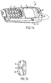
- Fig 1a and 1b show a hand-held unit 2 in the form of a mobile telephone, comprising a housing 3, a key pad 4 having a plurality of keys 5, a display 6, a light guide 8 for a light source 9, a light guide 10 for a light sensor 11 (cf. figure 2 for the light sources 9 and 11), a torch lens 12 and a rotary switch 14 associated with an on/off switch 15.
- Figure 2 shows a printed circuit board (PCB) 16 to be arranged inside the housing 3, comprising touch pads 18 to be arranged underneath the keys 5.
- display light sources 20 adapted to be arranged behind the display for illumination thereof from behind, so called back lighting.
- Key pad light sources 22 are adapted to be arranged on the PCB between touch pads 18 for illumination of the keys 5 from behind - the keys 5 are transparent or semi-transparent and are provided with printed numbers and letters.
- the keys may instead be generally non-transparent, however provided with transparent or semi-transparent letters and numbers.
- the PCB is provided with the attention light source 9 to be associated with the light guide 8, and the light sensor 11 to be associated with the light guide 10 and a torch light source 24 adapted to be arranged behind said torch lens 12.
- Figure 3 illustrates the opposite side of the printed circuit board shown in figure 2, including a microprocessor comprising a control means 25.
- Figures 4 and 5 show a hand-held unit 2 in the form of a personal pocket computer provided with a display 6 provided with a light source 20 in the form of an integrated illumination foil. When connected to electricity, the foil illuminates the display 6.
- the PCB is provided with a light sensor 11 to be associated with a light guide 10, a torch light source 24 to be arranged behind a torch lens 12 and a rotary switch 14 with integrated on/off switch 15.
- the PCB is furthermore provided with light sources 22 for the keys 5, and an attention light source 9, associated with the same light guide as the light sensor 11.
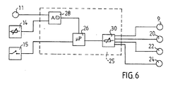
- FIG 6 is shown schematically how the light sources 9, 20, 22, 24, the light sensor 11, the rotary switch 14 and the on/off switch 15 are associated with a control means 25, comprising a microprocessor 26, an A/D-converter 28 provided for allowing the sensed light to be processed in the microprocessor 26 and a variable current limiter 30.
- a control means 25 comprising a microprocessor 26, an A/D-converter 28 provided for allowing the sensed light to be processed in the microprocessor 26 and a variable current limiter 30.
- the microprocessor 26 is connected to the light sources 9, 20, 22 and 24 via the variable current limiter 30, which is controllable by the microprocessor 26.
- the variable current limiter 30 provides the light sources 9, 20, 22 and 24 with variable current for allowing each light source to supply light of varying light intensity.
- the microprocessor further includes a timing program, which controls the period of time current is provided to each light source, separately or as a group.
- Figures 7a to 7c illustrate by means of graphs how the light intensity I of the light sources varies as a function of the said ambient light E.
- Figure 7a illustrates illumination of prior art hand-held units. All light sources provide a constant light intensity, disregarding the ambient light conditions.
- FIGS 7b and 7c illustrate illumination of hand-held units according to the invention.
- the continuous line relates to the light sources 20 for the display 6.
- the highest light intensity of the light sources is needed and thus provided at dim light conditions, i.e. when it is neither dark, nor light, e.g. at dusk or dawn, whereas in complete darkness, less light intensity on the display is provided in order to allow viewing the displayed information. In broad daylight or in illuminated rooms, no or little light intensity is provided.
- the broken line of the graph shown in figure 7b illustrates the provided illumination of the light sources 22 of the key-pad 4. In complete darkness, illumination is, of course, needed and thus provided. However, when it is neither dark, nor light, no light is provided, as the keys can be seen anyway, and do not need as much illumination as the display does.
- the continuous line relates to the attention light source and the broken line to the torch light source.
- Illumination of the attention lamp is provided in the same manner as regards the display light sources during complete darkness and during e.g. dusk or dawn. However, in broad daylight or in illuminated rooms, illumination of the attention light source is still provided at a maximum level, as the information supplied by the attention lamp is still needed then.
- the torch light source 24 is of course only needed when it is dark or almost dark, in order to illuminate e.g. the way in front of the user. However, it may instead be utilised by the user to be seen by others, e.g. when walking on a road at dusk or dawn. In that case, the timing program is preferably by-passed.
- the graphs shown in figures 7b and 7c are preferably stored as one or more programs in a memory to be executed by the microprocessor 26.
- the light sensor 10 senses the ambient light
- the control means 25 controls the light sources 20, 22, 24 etc. to provide the predetermined light intensity according to the relevant graph as a function of the sensed ambient light condition.
- the ambient light condition is determined by the user and the user provides a signal by manually turning the rotary switch 14. By turning it in one direction, a darker ambient light is indicated by the user, whereas, when turning it in the other direction lighter conditions are indicated.
- a control signal is provided to each light source 20, 22, 24 etc. in accordance with the graphs shown in figures 7b and 7c.
- the timing function limits the period of time the current is provided to the light sources, disregarding the light intensity, if above zero. It is however possible to separately switch off the light source 24 manually when not needed.
- the rotary switch may be used together with the light sensor 10, to adjust the light intensity, if the automatic control provided by the control means in response to the light sensor is considered too high or too low by the user.
- the torch light source may instead be a light or laser pointer.
- the attention light source 9 and the light sensor 11 may penetrate through the housing 3 instead of being associated with light guides 8, 10, however causing a more complicated way of tightening the housing against humidity.
- the rotary switch may be provided with a click-function to select control of a particular group of light sources having the same function.
- the program stored in the memory may not be used at all regarding one or several of the groups of light sources.
- each group of light sources may be switched completely off in order to save even more energy, or to be switched on to continuously obtain maximum light intensity.
- the torch light source may be switched on and off by a circuit breaker.
- the attention light source and the light sensor may be associated with a common light guide.
- the control of the light sources may instead be provided as discontinuous graphs, i.e. in steps. It should be noted that the attention light source 9, including the light guide 8, and the torch light source 24 and the torch lens 12 are optional regarding both the mobile telephone and the personal computer.
Landscapes
- Engineering & Computer Science (AREA)
- Signal Processing (AREA)
- Circuit Arrangement For Electric Light Sources In General (AREA)
Abstract
A hand-held electronic device provided with at least one microprocessor, such as a
mobile telephone, a personal computer or the like, comprises a control means, at
least one first light source (9, 20, 22, 24) and at least one a second light source (9,
20, 22, 24) each of which being associated with said control means (25), adapted to
control the light intensity of the first light source independently from the second
light source. According to the invention, said control means (25) is adapted to
variably adjust the light intensity, and in that said control means (25) is adapted to
control the light intensity depending on ambient light conditions.
Description
The present invention relates to a hand-held electronic device provided with at least
one microprocessor, such as a mobile telephone, a personal computer or the like,
comprising a control means, at least one first light source and at least one second
light source each of which being associated with said control means, adapted to
control the light intensity of the first light source independently from the second
light source.
Such hand-held devices in the form of mobile telephones are produced by Ericsson
Mobile Communications AB for many years; one light source illuminates the
display and the key pad, whereas another light source illuminates an attention lamp.
The light source for the display and the key pad may either illuminate them from
behind ("back light") or directly onto their surface ("front light"), and is switched on
e.g. when any button of the key pad is pressed down and is switched off after a
predetermined period of time thereafter. The attention lamp blinks intermittently or
continuously in green or red to inform the user of different modes, such as
connection to a network, incoming message or phone call, low battery level,
ongoing battery charge etc.
Another such hand-held unit is disclosed in US-A-5 894 298, according to which
two separate light sources are utilised in order to provide two different light
intensity levels for illumination of the screen or no light at all, in response to an
ambient light level detector, i.e. the darker it is, the more light is provided to the
display.
Other devices provided with controllable illumination of the display are disclosed in
US-A-5 337, 073, US-A-4 876 537, US-A-4 754 275, US-A-5 384 577 and
EP-A-0 907 158.
During the continuous development of mobile telephones, the demand for power has
increased, even though the electric consumption of the electronic circuits has
decreased, depending on the development of mobile telephones to more complex
units. As the customers demand small battery sizes, it has become important to
decrease the total electric consumption.
The object of the invention is therefore to improve the known hand-held device
regarding consumption of electric energy.
This object has been achieved by the hand-held unit of the initially defined kind,
wherein said control means is adapted to variably adjust the light intensity, and in
that said control means is adapted to control the light intensity depending on
ambient light conditions. Hereby is achieved longer use of the hand-held unit
between charging. Furthermore, when used in darkness, irritating strong light can be
avoided.
Preferably, said first light source provides light for a display and wherein said
second light source provides light for a key pad. Hereby is achieved that light can be
provided on the display when used e.g. at dusk or dawn or in other circumstances
with dim light conditions, whereas the key pad is still not illuminated or less
illuminated. During such light conditions, illumination of the key pad is simply a
waste of battery capacity.
Suitably, at least one third light source is adapted to give attention to the user, said
control means being adapted to control the light intensity of the third light source
depending on ambient light conditions. Hereby is achieved that also the attention
lamp is adjustable.
Advantageously, a light sensor for sensing ambient light is associated with said
control means, wherein said control means is adapted to control said light intensity
in response to the sensed ambient light. Hereby is achieved an automatic adjustment
of the illumination of the light sources, respectively.
Suitably, said control means is adapted to control the light intensity of the third light
source independently from the first light source and the second light source,
respectively. Alternatively, said control means is adapted to control the light
intensity of the third light source together with either of the first light source and the
second light source. Hereby, user options are created.
Advantageously, said control means is adapted to control at least one of said light
sources to provide a strongest light intensity during dim ambient light conditions,
and a less strong light intensity during darkness. Furthermore, said control means is
adapted to provide a less strong light intensity during bright ambient light
conditions. Hereby, light is provided when best needed.
Suitably, said control means is adapted to infinitely variably adjust the light
intensity. Alternatively, the light intensity is adjusted in steps. Hereby are achieved
different light intensities for different light conditions.
Advantageously, said control means is adapted to control said light sources by
means of predetermined light intensity profiles. Hereby is achieved different
illumination levels for different light conditions.
Preferably, at least one fourth light source is provided to illuminate an area beyond
the hand-held unit. Hereby, the hand-held unit may be used as a torch or as a
pointer.
Suitably, at least one manually operable switch member is provided for manually
adjusting the light intensity of said light sources. Hereby, manual adjustment
outgoing from the ambient light conditions is made possible, either as an alternative
or in addition to the automatic light intensity adjustment.
In particular, said switch member is a rotary switch, associated with an on/off
switch.
In the following, the invention will be described in further detail with reference to
the accompanying drawings, in which
Fig 1a and 1b show a hand-held unit 2 in the form of a mobile telephone,
comprising a housing 3, a key pad 4 having a plurality of keys 5, a display 6, a light
guide 8 for a light source 9, a light guide 10 for a light sensor 11 (cf. figure 2 for
the light sources 9 and 11), a torch lens 12 and a rotary switch 14 associated with
an on/off switch 15.
Figure 2 shows a printed circuit board (PCB) 16 to be arranged inside the housing 3,
comprising touch pads 18 to be arranged underneath the keys 5. Furthermore,
display light sources 20 adapted to be arranged behind the display for illumination
thereof from behind, so called back lighting. Key pad light sources 22 are adapted to
be arranged on the PCB between touch pads 18 for illumination of the keys 5 from
behind - the keys 5 are transparent or semi-transparent and are provided with
printed numbers and letters. Of course, the keys may instead be generally non-transparent,
however provided with transparent or semi-transparent letters and
numbers. Furthermore the PCB is provided with the attention light source 9 to be
associated with the light guide 8, and the light sensor 11 to be associated with the
light guide 10 and a torch light source 24 adapted to be arranged behind said torch
lens 12.
Figure 3 illustrates the opposite side of the printed circuit board shown in figure 2,
including a microprocessor comprising a control means 25.
Figures 4 and 5 show a hand-held unit 2 in the form of a personal pocket computer
provided with a display 6 provided with a light source 20 in the form of an
integrated illumination foil. When connected to electricity, the foil illuminates the
display 6. The PCB is provided with a light sensor 11 to be associated with a light
guide 10, a torch light source 24 to be arranged behind a torch lens 12 and a rotary
switch 14 with integrated on/off switch 15. The PCB is furthermore provided with
light sources 22 for the keys 5, and an attention light source 9, associated with the
same light guide as the light sensor 11.
In figure 6 is shown schematically how the light sources 9, 20, 22, 24, the light
sensor 11, the rotary switch 14 and the on/off switch 15 are associated with a control
means 25, comprising a microprocessor 26, an A/D-converter 28 provided for
allowing the sensed light to be processed in the microprocessor 26 and a variable
current limiter 30.
The microprocessor 26 is connected to the light sources 9, 20, 22 and 24 via the
variable current limiter 30, which is controllable by the microprocessor 26. The
variable current limiter 30 provides the light sources 9, 20, 22 and 24 with variable
current for allowing each light source to supply light of varying light intensity. The
microprocessor further includes a timing program, which controls the period of time
current is provided to each light source, separately or as a group.
Figures 7a to 7c illustrate by means of graphs how the light intensity I of the light
sources varies as a function of the said ambient light E.
Figure 7a illustrates illumination of prior art hand-held units. All light sources
provide a constant light intensity, disregarding the ambient light conditions.
Figures 7b and 7c illustrate illumination of hand-held units according to the
invention.
In figure 7b, the continuous line relates to the light sources 20 for the display 6. The
highest light intensity of the light sources is needed and thus provided at dim light
conditions, i.e. when it is neither dark, nor light, e.g. at dusk or dawn, whereas in
complete darkness, less light intensity on the display is provided in order to allow
viewing the displayed information. In broad daylight or in illuminated rooms, no or
little light intensity is provided.
The broken line of the graph shown in figure 7b illustrates the provided illumination
of the light sources 22 of the key-pad 4. In complete darkness, illumination is, of
course, needed and thus provided. However, when it is neither dark, nor light, no
light is provided, as the keys can be seen anyway, and do not need as much
illumination as the display does.
In figure 7c, the continuous line relates to the attention light source and the broken
line to the torch light source.
Illumination of the attention lamp is provided in the same manner as regards the
display light sources during complete darkness and during e.g. dusk or dawn.
However, in broad daylight or in illuminated rooms, illumination of the attention
light source is still provided at a maximum level, as the information supplied by the
attention lamp is still needed then.
The torch light source 24 is of course only needed when it is dark or almost dark, in
order to illuminate e.g. the way in front of the user. However, it may instead be
utilised by the user to be seen by others, e.g. when walking on a road at dusk or
dawn. In that case, the timing program is preferably by-passed.
The graphs shown in figures 7b and 7c are preferably stored as one or more
programs in a memory to be executed by the microprocessor 26. The light sensor 10
senses the ambient light, the control means 25 controls the light sources 20, 22, 24
etc. to provide the predetermined light intensity according to the relevant graph as a
function of the sensed ambient light condition.
However, instead of providing a signal regarding the ambient light condition by the
light sensor 10, the ambient light condition is determined by the user and the user
provides a signal by manually turning the rotary switch 14. By turning it in one
direction, a darker ambient light is indicated by the user, whereas, when turning it in
the other direction lighter conditions are indicated. When turning the rotary switch,
a control signal is provided to each light source 20, 22, 24 etc. in accordance with
the graphs shown in figures 7b and 7c.
Disregarding whether the light sources are controlled in response to the ambient
light sensor or in response to the rotary switch 14, which is turned in response to an
action by a person in response to the ambient light, the timing function limits the
period of time the current is provided to the light sources, disregarding the light
intensity, if above zero. It is however possible to separately switch off the light
source 24 manually when not needed.
It should be noted that the rotary switch may be used together with the light sensor
10, to adjust the light intensity, if the automatic control provided by the control
means in response to the light sensor is considered too high or too low by the user.
It is contemplated that the invention may be modified within the scope of the
accompanying claims. Thus, the torch light source may instead be a light or laser
pointer. The attention light source 9 and the light sensor 11 may penetrate through
the housing 3 instead of being associated with light guides 8, 10, however causing a
more complicated way of tightening the housing against humidity. Furthermore, the
rotary switch may be provided with a click-function to select control of a particular
group of light sources having the same function. Furthermore, there may be one
rotary switch for each group of light sensors having the same function. Furthermore,
as a user option, the program stored in the memory may not be used at all regarding
one or several of the groups of light sources. Consequently, each group of light
sources may be switched completely off in order to save even more energy, or to be
switched on to continuously obtain maximum light intensity. Accordingly, e.g. the
torch light source may be switched on and off by a circuit breaker. Furthermore, the
attention light source and the light sensor may be associated with a common light
guide. Furthermore, the control of the light sources may instead be provided as
discontinuous graphs, i.e. in steps. It should be noted that the attention light
source 9, including the light guide 8, and the torch light source 24 and the torch lens
12 are optional regarding both the mobile telephone and the personal computer.
Claims (13)
- A hand-held electronic device provided with at least one microprocessor, such as a mobile telephone, a personal computer or the like, comprising a control means (25), at least one first light source (9, 20, 22, 24) and at least one a second light source (9, 20, 22, 24) each of which being associated with said control means (25), adapted to control the light intensity of the first light source independently from the second light source, characterised in that said control means is adapted to variably adjust the light intensity, and in that said control means is adapted to control the light intensity depending on ambient light conditions (Figures 7b-7c).
- A device according to claim 1, wherein said first light source (20) provides light for a display and wherein said second light source (22) provides light for a key pad.
- A device according to claim 1 or 2, wherein at least one third light source (9) is adapted to give attention to the user, said control means (25) being adapted to control the light intensity of the third light source (9) depending on ambient light conditions.
- A device according to anyone of claims 1 to 3, wherein a light sensor (11) for sensing ambient light is associated with said control means (25), wherein said control means is adapted to control said light intensity in response to the sensed ambient light.
- A device according to claim 3 or 4, wherein said control means (25) is adapted to control the light intensity of the third light source (9) independently from the first light source (20) and the second light source (22), respectively.
- A device according to claim 3 or 4, wherein said control means (25) is adapted to control the light intensity of the third light source (9) together with either of the first light source (20) and the second light source (22).
- A device according to anyone of the preceding claims, wherein said control means (25) is adapted to control at least one of said light sources (9, 20, 22) to provide a strongest light intensity during dim ambient light conditions, and a less strong light intensity during darkness.
- A device according to anyone of the preceding claims, wherein said control means (25) is adapted to provide a less strong light intensity during bright ambient light conditions.
- A device according to anyone of the preceding claims, wherein said control means (25) is adapted to infinitely variably adjust the light intensity.
- A device according to claim 9, wherein said control means (25) is adapted to control said light sources by means of predetermined light intensity profiles (Figures 7b-7c).
- A device according to anyone of the preceding claims, wherein at least one fourth light source (24) is provided to illuminate an area beyond the hand-held unit.
- A device according to anyone of the preceding claims, wherein at least one manually operable switch member (14, 15) is provided for manually adjusting the light intensity of said light sources.
- A device according to claim 12, wherein said switch member comprises rotary switch (14) associated with an on/off switch (15).
Priority Applications (1)
| Application Number | Priority Date | Filing Date | Title |
|---|---|---|---|
| EP01200284A EP1227642A1 (en) | 2001-01-26 | 2001-01-26 | Back light device for a hand-held electronic device |
Applications Claiming Priority (1)
| Application Number | Priority Date | Filing Date | Title |
|---|---|---|---|
| EP01200284A EP1227642A1 (en) | 2001-01-26 | 2001-01-26 | Back light device for a hand-held electronic device |
Publications (1)
| Publication Number | Publication Date |
|---|---|
| EP1227642A1 true EP1227642A1 (en) | 2002-07-31 |
Family
ID=8179805
Family Applications (1)
| Application Number | Title | Priority Date | Filing Date |
|---|---|---|---|
| EP01200284A Withdrawn EP1227642A1 (en) | 2001-01-26 | 2001-01-26 | Back light device for a hand-held electronic device |
Country Status (1)
| Country | Link |
|---|---|
| EP (1) | EP1227642A1 (en) |
Cited By (10)
| Publication number | Priority date | Publication date | Assignee | Title |
|---|---|---|---|---|
| GB2391752A (en) * | 2002-08-07 | 2004-02-11 | Nec Technologies | Reducing power consumption of display illumination |
| WO2005029454A1 (en) | 2003-09-24 | 2005-03-31 | Koninklijke Philips Electronics N.V. | Method and system for controlling an illuminating apparatus |
| US7071456B2 (en) * | 2004-03-30 | 2006-07-04 | Poplin Dwight D | Camera module with ambient light detection |
| EP1701331A1 (en) * | 2005-03-07 | 2006-09-13 | Research In Motion Limited | System and method for adjusting a backlight for a display for an electronic device |
| EP1654810A4 (en) * | 2003-08-14 | 2007-07-04 | Motorola Inc | Ambient light controlled display and method of operation background of the invention |
| EP1740884A4 (en) * | 2004-04-02 | 2007-12-26 | Ixi Mobile R & D Ltd | Illumination system and method for a mobile computing device |
| EP1665235A4 (en) * | 2003-11-18 | 2009-02-25 | Microsoft Corp | ADAPTIVE COMPUTING ENVIRONMENT |
| EP1754023A4 (en) * | 2004-02-13 | 2010-04-28 | Radica Entpr Ltd | Light display for a video game device |
| EP2654272A1 (en) * | 2012-04-17 | 2013-10-23 | Samsung Electronics Co., Ltd | Method and apparatus for using portable terminal |
| WO2024208626A1 (en) | 2023-04-04 | 2024-10-10 | Signify Holding B.V. | Switching on a mobile device's display based on lighting device settings |
Citations (6)
| Publication number | Priority date | Publication date | Assignee | Title |
|---|---|---|---|---|
| US5747938A (en) * | 1994-10-18 | 1998-05-05 | Norand Corporation | Automatic control electroluminescent backlight panel |
| GB2339648A (en) * | 1998-04-20 | 2000-02-02 | Nec Corp | Cellular phone with cover and absence reception display means |
| WO2000041378A1 (en) * | 1998-12-31 | 2000-07-13 | Nokia Mobile Phones Limited | Backlight for a portable device |
| DE19930442A1 (en) * | 1999-07-02 | 2001-01-11 | Petra Schuetze | Telephone, especially mobile telephone, has auxiliary device, e.g. torch or laser pointer, integrated into telephone housing and powered by telephone's battery or an independent supply |
| JP2001004978A (en) * | 1999-06-22 | 2001-01-12 | Kyocera Corp | Backlight control method for information terminal equipment |
| US6175353B1 (en) * | 1997-03-14 | 2001-01-16 | Nortel Networks Limited | Display apparatus |
-
2001
- 2001-01-26 EP EP01200284A patent/EP1227642A1/en not_active Withdrawn
Patent Citations (6)
| Publication number | Priority date | Publication date | Assignee | Title |
|---|---|---|---|---|
| US5747938A (en) * | 1994-10-18 | 1998-05-05 | Norand Corporation | Automatic control electroluminescent backlight panel |
| US6175353B1 (en) * | 1997-03-14 | 2001-01-16 | Nortel Networks Limited | Display apparatus |
| GB2339648A (en) * | 1998-04-20 | 2000-02-02 | Nec Corp | Cellular phone with cover and absence reception display means |
| WO2000041378A1 (en) * | 1998-12-31 | 2000-07-13 | Nokia Mobile Phones Limited | Backlight for a portable device |
| JP2001004978A (en) * | 1999-06-22 | 2001-01-12 | Kyocera Corp | Backlight control method for information terminal equipment |
| DE19930442A1 (en) * | 1999-07-02 | 2001-01-11 | Petra Schuetze | Telephone, especially mobile telephone, has auxiliary device, e.g. torch or laser pointer, integrated into telephone housing and powered by telephone's battery or an independent supply |
Non-Patent Citations (1)
| Title |
|---|
| PATENT ABSTRACTS OF JAPAN vol. 2000, no. 16 8 May 2001 (2001-05-08) * |
Cited By (16)
| Publication number | Priority date | Publication date | Assignee | Title |
|---|---|---|---|---|
| GB2391752A (en) * | 2002-08-07 | 2004-02-11 | Nec Technologies | Reducing power consumption of display illumination |
| EP1654810A4 (en) * | 2003-08-14 | 2007-07-04 | Motorola Inc | Ambient light controlled display and method of operation background of the invention |
| WO2005029454A1 (en) | 2003-09-24 | 2005-03-31 | Koninklijke Philips Electronics N.V. | Method and system for controlling an illuminating apparatus |
| US7714521B2 (en) | 2003-09-24 | 2010-05-11 | Koninklijke Philips Electronics N.V. | Methods and system for controlling an illuminating apparatus |
| CN100483485C (en) * | 2003-09-24 | 2009-04-29 | 皇家飞利浦电子股份有限公司 | Method and system for controlling illuminating apparatus |
| EP1665235A4 (en) * | 2003-11-18 | 2009-02-25 | Microsoft Corp | ADAPTIVE COMPUTING ENVIRONMENT |
| EP1754023A4 (en) * | 2004-02-13 | 2010-04-28 | Radica Entpr Ltd | Light display for a video game device |
| US8337303B2 (en) | 2004-02-13 | 2012-12-25 | Mattel, Inc. | Light display for a video game device |
| US7071456B2 (en) * | 2004-03-30 | 2006-07-04 | Poplin Dwight D | Camera module with ambient light detection |
| EP1740884A4 (en) * | 2004-04-02 | 2007-12-26 | Ixi Mobile R & D Ltd | Illumination system and method for a mobile computing device |
| EP1701331A1 (en) * | 2005-03-07 | 2006-09-13 | Research In Motion Limited | System and method for adjusting a backlight for a display for an electronic device |
| EP2654272A1 (en) * | 2012-04-17 | 2013-10-23 | Samsung Electronics Co., Ltd | Method and apparatus for using portable terminal |
| JP2013223249A (en) * | 2012-04-17 | 2013-10-28 | Samsung Electronics Co Ltd | Method and device for using portable terminal |
| US9265126B2 (en) | 2012-04-17 | 2016-02-16 | Samsung Electronics Co., Ltd. | Method and apparatus for using portable terminal |
| CN103379198B (en) * | 2012-04-17 | 2019-01-22 | 三星电子株式会社 | Method and device for using portable terminal |
| WO2024208626A1 (en) | 2023-04-04 | 2024-10-10 | Signify Holding B.V. | Switching on a mobile device's display based on lighting device settings |
Similar Documents
| Publication | Publication Date | Title |
|---|---|---|
| JP3438693B2 (en) | Electronic device with display | |
| EP1303113B1 (en) | Portable terminal | |
| US6426736B1 (en) | Portable telephone with liquid crystal display | |
| US8363015B2 (en) | Automatic keypad backlight adjustment on a mobile handheld electronic device | |
| US7117019B2 (en) | Display and keypad backlight management for portable electronic devices | |
| JP2002534912A (en) | Portable devices | |
| CN101778504A (en) | System and method for automatically adjusting brightness of backlight lamps of screen and keys | |
| EP1227642A1 (en) | Back light device for a hand-held electronic device | |
| WO2000041378A1 (en) | Backlight for a portable device | |
| GB2342247A (en) | Mobile phone display and/or keypad illumination is turned off when call is being made to conserve power | |
| US8665203B2 (en) | Electronic device having display and method for controlling display brightness | |
| EP1195971A2 (en) | Portable information terminal apparatus having illumination control function | |
| JP2000324238A (en) | Lighting device for mobile radio unit | |
| EP2224696B1 (en) | Automatic keypad backlight adjustment on a mobile handheld electronic device | |
| KR100221285B1 (en) | How to adjust the handset backlight | |
| KR101208974B1 (en) | Brightness of backlight control apparatus and method for mobile communication device | |
| JPH07131511A (en) | Telephone | |
| JP2837765B2 (en) | Mobile radio lighting system | |
| JP5453931B2 (en) | Liquid crystal display device, power supply method used in the liquid crystal display device, and electronic apparatus having the liquid crystal display device | |
| JP2001175229A (en) | Mobile phone | |
| CN101098354A (en) | Handhold electronic device and method capable of auto-adjusting backlight brightness | |
| KR100480062B1 (en) | Backlight control method for mobile communication device | |
| JP4514815B2 (en) | Portable electronic device and display control method thereof | |
| KR19980023438A (en) | Operation Structure of Light-Emitting Diode of Mobile Phone Using Optical Sensor | |
| CN119479543A (en) | Display brightness adjustment method and device, electronic device and storage medium |
Legal Events
| Date | Code | Title | Description |
|---|---|---|---|
| PUAI | Public reference made under article 153(3) epc to a published international application that has entered the european phase |
Free format text: ORIGINAL CODE: 0009012 |
|
| AK | Designated contracting states |
Kind code of ref document: A1 Designated state(s): AT BE CH CY DE DK ES FI FR GB GR IE IT LI LU MC NL PT SE TR |
|
| AX | Request for extension of the european patent |
Free format text: AL;LT;LV;MK;RO;SI |
|
| AKX | Designation fees paid | ||
| REG | Reference to a national code |
Ref country code: DE Ref legal event code: 8566 |
|
| STAA | Information on the status of an ep patent application or granted ep patent |
Free format text: STATUS: THE APPLICATION IS DEEMED TO BE WITHDRAWN |
|
| 18D | Application deemed to be withdrawn |
Effective date: 20030201 |