EP1227590A1 - Procédé et dispositif d'élaboration d'une tension d'alimentation nécessaire au pilotage d'un interrupteur électronique - Google Patents
Procédé et dispositif d'élaboration d'une tension d'alimentation nécessaire au pilotage d'un interrupteur électronique Download PDFInfo
- Publication number
- EP1227590A1 EP1227590A1 EP02290054A EP02290054A EP1227590A1 EP 1227590 A1 EP1227590 A1 EP 1227590A1 EP 02290054 A EP02290054 A EP 02290054A EP 02290054 A EP02290054 A EP 02290054A EP 1227590 A1 EP1227590 A1 EP 1227590A1
- Authority
- EP
- European Patent Office
- Prior art keywords
- electronic switch
- voltage
- auxiliary
- switch
- circuit
- Prior art date
- Legal status (The legal status is an assumption and is not a legal conclusion. Google has not performed a legal analysis and makes no representation as to the accuracy of the status listed.)
- Granted
Links
- 238000000034 method Methods 0.000 title claims description 6
- 230000001105 regulatory effect Effects 0.000 claims abstract description 4
- 239000003990 capacitor Substances 0.000 claims description 12
- 230000001276 controlling effect Effects 0.000 claims description 3
- 230000007935 neutral effect Effects 0.000 description 5
- 238000010586 diagram Methods 0.000 description 2
- 230000008033 biological extinction Effects 0.000 description 1
- 239000004020 conductor Substances 0.000 description 1
- 230000006378 damage Effects 0.000 description 1
- 230000002349 favourable effect Effects 0.000 description 1
- 230000007257 malfunction Effects 0.000 description 1
- 239000002184 metal Substances 0.000 description 1
- 244000045947 parasite Species 0.000 description 1
- 239000010453 quartz Substances 0.000 description 1
- VYPSYNLAJGMNEJ-UHFFFAOYSA-N silicon dioxide Inorganic materials O=[Si]=O VYPSYNLAJGMNEJ-UHFFFAOYSA-N 0.000 description 1
Images
Classifications
-
- H—ELECTRICITY
- H02—GENERATION; CONVERSION OR DISTRIBUTION OF ELECTRIC POWER
- H02M—APPARATUS FOR CONVERSION BETWEEN AC AND AC, BETWEEN AC AND DC, OR BETWEEN DC AND DC, AND FOR USE WITH MAINS OR SIMILAR POWER SUPPLY SYSTEMS; CONVERSION OF DC OR AC INPUT POWER INTO SURGE OUTPUT POWER; CONTROL OR REGULATION THEREOF
- H02M3/00—Conversion of DC power input into DC power output
- H02M3/02—Conversion of DC power input into DC power output without intermediate conversion into AC
- H02M3/04—Conversion of DC power input into DC power output without intermediate conversion into AC by static converters
- H02M3/10—Conversion of DC power input into DC power output without intermediate conversion into AC by static converters using discharge tubes with control electrode or semiconductor devices with control electrode
- H02M3/145—Conversion of DC power input into DC power output without intermediate conversion into AC by static converters using discharge tubes with control electrode or semiconductor devices with control electrode using devices of a triode or transistor type requiring continuous application of a control signal
- H02M3/155—Conversion of DC power input into DC power output without intermediate conversion into AC by static converters using discharge tubes with control electrode or semiconductor devices with control electrode using devices of a triode or transistor type requiring continuous application of a control signal using semiconductor devices only
-
- H—ELECTRICITY
- H03—ELECTRONIC CIRCUITRY
- H03K—PULSE TECHNIQUE
- H03K17/00—Electronic switching or gating, i.e. not by contact-making and –breaking
- H03K17/51—Electronic switching or gating, i.e. not by contact-making and –breaking characterised by the components used
- H03K17/56—Electronic switching or gating, i.e. not by contact-making and –breaking characterised by the components used by the use, as active elements, of semiconductor devices
- H03K17/72—Electronic switching or gating, i.e. not by contact-making and –breaking characterised by the components used by the use, as active elements, of semiconductor devices having more than two PN junctions; having more than three electrodes; having more than one electrode connected to the same conductivity region
- H03K17/725—Electronic switching or gating, i.e. not by contact-making and –breaking characterised by the components used by the use, as active elements, of semiconductor devices having more than two PN junctions; having more than three electrodes; having more than one electrode connected to the same conductivity region for AC voltages or currents
-
- H—ELECTRICITY
- H05—ELECTRIC TECHNIQUES NOT OTHERWISE PROVIDED FOR
- H05B—ELECTRIC HEATING; ELECTRIC LIGHT SOURCES NOT OTHERWISE PROVIDED FOR; CIRCUIT ARRANGEMENTS FOR ELECTRIC LIGHT SOURCES, IN GENERAL
- H05B47/00—Circuit arrangements for operating light sources in general, i.e. where the type of light source is not relevant
- H05B47/10—Controlling the light source
-
- H—ELECTRICITY
- H03—ELECTRONIC CIRCUITRY
- H03K—PULSE TECHNIQUE
- H03K2217/00—Indexing scheme related to electronic switching or gating, i.e. not by contact-making or -breaking covered by H03K17/00
- H03K2217/0081—Power supply means, e.g. to the switch driver
Definitions
- the invention relates to a method and a device for producing a supply voltage, necessary to supply the control means of a electronic switch, for example of the triac type or the like. It aims more particularly to develop such a direct voltage suitable for supplying electronic control circuits when said switch is wired in two wires to control the supply of a load (such as for example a lamp that is to say more particularly when it is connected in series with said load between phase and neutral of a current distribution network single-phase AC.
- a load such as for example a lamp that is to say more particularly when it is connected in series with said load between phase and neutral of a current distribution network single-phase AC.
- the electronic switch (the triac) replaces the classic metal contact switch. It is therefore placed with its electronic control circuits in a box recessed in the wall where no most often only two sons will be called here for convenience the "phase” and "phase cut”.
- the electric switch is of course connected between the two available wires, i.e. between said phase and said phase cut.
- the load is connected between the wire called “phase cut "and the neutral which is not accessible.
- the document EP 0 031 626 nevertheless describes a circuit for supplying direct current, for driving a triac, which takes electrical energy necessary on the network using a capacitor and a rectifier circuit.
- This circuit can only develop a usable DC voltage if the triac is blocked. Therefore, the solution proposed in this earlier document consists in interrupting the conduction of the triac at each alternation, for a short time interval required to develop a DC voltage usable for supplying the pilot circuits of said triac.
- the invention proposes another solution which consists in exploiting the voltage residual at the terminals of the controlled switch when it is driver.
- the invention relates to a method for preparing a auxiliary supply voltage required to operate a switch electronics connected in series with a load to a distribution network of single-phase alternating current, characterized in that, during the periods of time when said electronic switch is in conduction state, the sample is taken the electrical energy required to develop said supply voltage auxiliary at the terminals of said electronic switch by exploiting a drop of residual voltage available between said terminals.
- this drop in AC residual voltage is around of the Volt. It is therefore advantageous to straighten and raise this voltage drop residual, for example by means of a rectifier-step-up circuit, of a known type. We can thus obtain a voltage of the order of 5 Volts or more, perfectly usable for DC power supply piloting of the electronic switch.
- the invention also relates to a power control device.
- electric for a load of the type comprising an electronic switch controlled intended to be connected in series with said load for its powered by a single-phase alternating current distribution network and means for controlling said switch, characterized in that it comprises a first auxiliary DC power supply circuit, connected for supplying said control means, in that this first circuit comprises an electrical energy input in alternating current and in that said means control devices are arranged to connect said input to the terminals of said electronic switch when it is on.
- said first supply circuit auxiliary will preferably include a voltage rectifier-booster.
- This device may for example be of the switching power supply type, regulated.
- the device defined above is also characterized in that that it has a second auxiliary DC power supply circuit, connected as input to said AC distribution network and arranged for supplying said control means when said electronic switch is not in a state of conduction.
- This second auxiliary supply circuit consists of a simple rectifier connected to the distribution network by a capacitor.
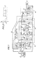
- a distribution network of single-phase alternating current 11 equipping for example a room.
- a phase P and a neutral N we distinguish a phase P and a neutral N.
- a load 12 in this case here, a lamp can be supplied with alternating current from this network.
- the load can be any electrical device intended to be supplied with alternating current.
- an electronic switch 13 of the triac type is connected in series with said load and the assembly is connected between phase P and the neutral N.
- the electronic switch is installed, that is to say for example in a box recessed in the wall, there are only two available wires, i.e., for example, phase and cut phase Pc, depending on the definition above.
- the triac 13 is connected between these two wires.
- the sentence cut is connected to load 12.
- Neutral N is not accessible directly at the location where the electronic switch is located.
- the control of said electronic switch 13 requires means of electronic controls requiring, for their operation, a voltage continuous feeding.
- the triac control means comprise a control circuit 16 itself controlled by a user interface 17 as well as a connection interface 18 controlled by said control circuit.
- the control circuit 16 essentially comprises a microcontroller 20.
- the 8-bit microcontroller bearing the reference ST6200 manufactured by SGS THOMSON®. It is connected here in a classic way recommended by the manufacturer. Its operation requires the addition of a quartz 21. It has two logic outputs respectively connected to the bases of two transistors Q1, Q2.
- the transistor Q1 is of the PNP type and the transistor Q2 is of the NPN type. These two transistors drive respectively two coils L1 (on) and L2 (on) of a bistable relay 22 with two switches I1, I2, which constitutes the main part of the connection interface 18 installed between the triac 13 and a first auxiliary power supply circuit continuous 25, constituting the essential feature of the invention.
- the user interface 17 is reduced to a simple push button connected between an input of the microcontroller and said phase cut Pc. It should be noted however that the interest of such a system is to be able associate with the microcontroller any type of user interface, for example a infrared receiver, HF reflector, or other.
- the DC voltage available at the output of said first circuit auxiliary power supply 25 enables the components of the control circuit 16 as the coils of the relay 22.
- the mounting of the interface of connection is as follows. Phase P is connected to one pole of each switch I1, I2.
- the triac trigger is connected to the other pole of the I2 switch.
- said first auxiliary supply circuit 25 carries a input of electrical energy in alternating current 28 (in the form of a dipole) which is connected to the other pole of switch I1 and to the cut phase Pc, i.e. the accessible conductor connected to the lamp 12.
- connection of the two switches I1, I2 is such that, in one of the positions (switches I1, I2 open), phase P is connected neither to the electrical energy input 28, nor to the triac trigger 13. In the other position (switches I1, I2 closed), said electrical energy input is connected between phase and cut phase, that is to say at the terminals of the triac 13 and the phase is connected to the trigger of the triac.
- the relay 22 is of the bistable type. It is powered only during state changes. This is a relay to DC power supply.
- This relay has the distinction of having two coils: L1 for switching on and L2 for tripping. The fact power the coil L2, trips the relay and opens the two switches L1 and L2.
- the coil L1 is connected between the DC voltage output of said first auxiliary power circuit and the emitter of transistor Q1.
- the L2 coil is connected between the emitter of transistor Q2 and said cut phase Pc.
- a diode D1, D2 is connected in parallel on each coil L1, L2 for the protect against overvoltages when the transistor Q1, Q2 is blocked which the command.
- a Zener Z1 diode is connected between the triac trigger and the electrical energy input 28 (the anode being on the trigger side).
- the role of this Zener diode is to protect the first auxiliary power circuit 25. More specifically, if the switch I1 is closed when the triac is blocked (which is a malfunction) the Zener initiates the triac, which prevents the distribution network alternating voltage applied to the energy input electric 28, which would cause the destruction of said first circuit auxiliary power supply 25.
- the latter includes an output dipole 30 aux terminals from which a DC voltage, of the order of 5 Volts, is available for supply the triac control means, i.e. essentially here, the relay 22 and the control circuit 16. One of the poles of the output dipole is connected to the phase cut.
- the first auxiliary supply circuit 25 is arranged in voltage rectifier-booster comprising a self-inductance L and a diode D connected in series as well as a capacitor C connected in parallel to the dipole These components are connected to an integrated circuit 26 (type LT 1073, for example) designed to constitute a switching power supply associated with regulatory means.
- the self-inductance L is connected between the terminal of input 28 which is connected to switch I1 and the anode of diode D.
- a MOS-type transistor M1 with its drain-source connection connected between the point common of the self-inductance L and the diode D and said phase cut.
- Her grid is connected to a resistor R1 whose opposite terminal is connected to the emitter of a transistor Q3.
- the collector of this transistor is connected to said phase cut.
- a diode D3 is connected between the collector and the base of the transistor Q3.
- a bias resistor R2 is connected between the base of this transistor and said phase cut.
- the base of transistor Q3 is connected to an output of the integrated circuit. This is also connected (output 8) to the cathode of the diode D.
- the transistor M1 is actually an external switch used to preference to that provided in the integrated circuit, to obtain better efficiency.
- the circuit part comprising the transistor Q3, the diode D3 and the resistance R2 only constitutes a system for assisting the opening of transistor M1.
- a high value capacitor C1 is connected in parallel on input 28 to ensure single-phase rectification of the voltage across the dipole and eliminate "HF returns" to the current distribution network alternative.
- Auxiliary DC supply voltage is available at the terminals of the output dipole 30, that is to say between the cathode of the diode D and said phase cut.
- a Zener Z2 diode acting as a voltage limiter is connected in parallel on capacitor C. The operation of the auxiliary power supply will be described in more detail below.
- the auxiliary supply voltage available at the output dipole 30 makes it possible to supply both the control circuit 16 and the relay 22. More specifically, the cathode of the diode D is connected to the power input (input 1) of the microcontroller 20, to the collector of the transistor Q2 and to the coil L1 of the relay 22.
- the first auxiliary power circuit 25 is here designed to develop said voltage auxiliary only when the triac 13 is conductive. When the triac is blocked, this auxiliary voltage is produced by a second auxiliary supply circuit 35, much simpler, which comprises a series branch comprising a resistor R3, a capacitor C3 and a diode D4. The other terminal of the resistor R3 is connected to the triac 13, on the phase side.
- the cathode of diode D4 is connected to the output of the first auxiliary supply circuit 25, that is to say more precisely to the cathode of diode D.
- a diode D5 has its cathode connected between the common point of the capacitor C3 and diode D4 and its anode connected to said cut phase.
- the operation is as follows.
- the control circuit 16 causes relay 22 to engage.
- the triac trigger 13 is commanded and it enters into conduction.
- the lamp 12 is supplied.
- a drop of alternating voltage of approximately 1 Volt, as shown in Figure 2.
- This residual voltage because the switch I1 is closed, is found at the terminals of input 28.
- the self-inductance L is charged at through transistor M1 when it is in the on state then, at the opening of this same transistor, the energy accumulated in the self-inductance is transferred to capacitor C via diode D.
- the overvoltage created makes it possible to charge the capacitor C up to a voltage of the order of 5 volts, which is sufficient for supply the control means 16, 18.
- the control circuit causes the triggering of the relay, switches I1 and I2 open, triac locks, power supply auxiliary 25 is neutralized.
- the charge of the capacitor C is maintained via the second auxiliary supply circuit 35.
- the latter is behaves like a voltage step-down rectifier which can develop a sufficient rectified voltage as soon as the triac 13 is blocked since, in these conditions, an AC voltage from the distributor network is available at the auxiliary supply circuit input 35.
Landscapes
- Engineering & Computer Science (AREA)
- Power Engineering (AREA)
- Power Conversion In General (AREA)
- Rectifiers (AREA)
- Control Of Electrical Variables (AREA)
- Semiconductor Integrated Circuits (AREA)
Abstract
Description
- la figure 1 est un schéma de principe du dispositif électronique ; et
- la figure 2 est un chronogramme illustrant la tension alternative disponible aux bornes de l'interrupteur électronique lorsque celui-ci est en état de conduction.
de la diode D est reliée à l'entrée d'alimentation (entrée 1) du microcontrôleur 20, au collecteur du transistor Q2 et à la bobine L1 du relais 22. Le premier circuit d'alimentation auxiliaire 25 est ici conçu pour élaborer ladite tension auxiliaire seulement lorsque le triac 13 est conducteur. Lorsque le triac est bloqué, cette tension auxiliaire est élaborée par un second circuit d'alimentation auxiliaire 35, beaucoup plus simple, qui comporte une branche série comprenant une résistance R3, un condensateur C3 et une diode D4. L'autre borne de la résistance R3 est reliée au triac 13, du côté phase. La cathode de la diode D4 est connectée à la sortie du premier circuit d'alimentation auxiliaire 25, c'est-à-dire plus précisément à la cathode de la diode D. Une diode D5 a sa cathode connectée entre le point commun du condensateur C3 et de la diode D4 et son anode connectée à ladite phase coupée.
Claims (14)
- Procédé d'élaboration d'une tension d'alimentation auxiliaire nécessaire au pilotage d'un interrupteur électronique connecté en série avec une charge (12) à un réseau de distribution de courant alternatif monophasé, caractérisé en ce que, pendant les périodes de temps où ledit interrupteur électronique (13) est en état de conduction, on prélève l'énergie électrique nécessaire à l'élaboration de ladite tension d'alimentation auxiliaire aux bornes dudit interrupteur électronique en exploitant une chute de tension résiduelle, disponible entre lesdites bornes.
- Procédé selon la revendication 1, caractérisé en ce qu'on redresse et élève (25) ladite chute de tension, jusqu'à disposer de ladite tension d'alimentation auxiliaire.
- Procédé selon la revendication 1 ou 2, caractérisé en ce qu'on élabore (35) ladite tension d'alimentation auxiliaire à partir de la tension dudit réseau pendant les périodes de temps où ledit interrupteur électronique est bloqué.
- Dispositif électronique de commande d'alimentation électrique pour une charge (12), du type comportant un interrupteur électronique (13) commandé destiné à être connecté en série avec ladite charge pour son alimentation par un réseau de distribution de courant alternatif monophasé et des moyens de commande (16, 17, 18) dudit interrupteur, caractérisé en ce qu'il comporte un premier circuit d'alimentation auxiliaire en courant continu (25), connecté pour alimenter lesdits moyens de commande, en ce que ce premier circuit comporte une entrée d'énergie électrique en courant alternatif (28) et en ce que lesdits moyens de commande sont agencés pour connecter ladite entrée aux bornes dudit interrupteur électronique (13) lorsqu'il est à l'état passant.
- Dispositif selon la revendication 4, caractérisé en ce que ledit premier circuit d'alimentation auxiliaire (25) comporte un redresseur-élévateur de tension.
- Dispositif selon la revendication 5, caractérisé en ce que ledit redresseur-élévateur de tension est du type alimentation à découpage régulée.
- Dispositif selon l'une des revendications 4 à 6, caractérisé en ce que lesdits moyens de commande comportent une interface de connexion (18) commandée, interconnectée entre ledit interrupteur électronique (13) et ladite entrée d'énergie électrique en courant alternatif (28).
- Dispositif selon la revendication 7, caractérisé en ce que ladite interface de connexion comporte un relais électromagnétique (22) comprenant un premier interrupteur (I1) connecté entre ladite entrée d'énergie électrique (28) et ledit interrupteur électronique (13).
- Dispositif selon l'une des revendications précédentes, caractérisé en ce que ledit interrupteur électronique (13) est du type triac ou analogue.
- Dispositif selon l'ensemble des revendications 8 et 9, caractérisé en ce que ledit relais électromagnétique comporte un second interrupteur (I2) connecté entre la phase et l'électrode de commande dudit interrupteur électronique.
- Dispositif selon l'une des revendications 8 à 10, caractérisé en ce que ledit relais électromagnétique (22) est du type bistable.
- Dispositif selon la revendication 11, caractérisé en ce que ledit relais électromagnétique (22) comporte deux bobines (L1, L2) respectivement alimentées par l'intermédiaire de deux interrupteurs commandés (Q1, Q2) faisant partie d'un circuit de pilotage (16), lui-même piloté par une interface-utilisateur (17).
- Dispositif selon l'une des revendications précédentes, caractérisé en ce qu'il comporte un second circuit d'alimentation auxiliaire en courant continu (35), relié en entrée audit réseau de distribution de courant alternatif et agencé pour alimenter lesdits moyens de commande lorsque ledit interrupteur électronique (13) n'est pas en état de conduction.
- Dispositif selon la revendication 13, caractérisé en ce que ledit second circuit d'alimentation auxiliaire consiste en un redresseur relié audit réseau de distribution par une résistance (R3) et un condensateur (C3).
Applications Claiming Priority (2)
| Application Number | Priority Date | Filing Date | Title |
|---|---|---|---|
| FR0100267 | 2001-01-10 | ||
| FR0100267A FR2819355B1 (fr) | 2001-01-10 | 2001-01-10 | Procede et dispositif d'elaboration d'une tension d'alimentation necessaire au pilotage d'un interrupteur electronique |
Publications (2)
| Publication Number | Publication Date |
|---|---|
| EP1227590A1 true EP1227590A1 (fr) | 2002-07-31 |
| EP1227590B1 EP1227590B1 (fr) | 2012-08-01 |
Family
ID=8858655
Family Applications (1)
| Application Number | Title | Priority Date | Filing Date |
|---|---|---|---|
| EP02290054A Expired - Lifetime EP1227590B1 (fr) | 2001-01-10 | 2002-01-10 | Procédé et dispositif d'élaboration d'une tension d'alimentation nécessaire au pilotage d'un interrupteur électronique |
Country Status (5)
| Country | Link |
|---|---|
| US (1) | US6690150B2 (fr) |
| EP (1) | EP1227590B1 (fr) |
| JP (1) | JP2002305870A (fr) |
| ES (1) | ES2391088T3 (fr) |
| FR (1) | FR2819355B1 (fr) |
Families Citing this family (4)
| Publication number | Priority date | Publication date | Assignee | Title |
|---|---|---|---|---|
| DE102008031536A1 (de) * | 2008-07-03 | 2010-01-14 | Fujitsu Technology Solutions Gmbh | Schaltungsanordnung und Ansteuerschaltung für ein Netzteil, Computernetzteil und Verfahren zum Schalten eines Netzteils |
| DE102009037859B4 (de) | 2009-08-18 | 2017-02-23 | Fujitsu Technology Solutions Intellectual Property Gmbh | Eingangsschaltung für ein elektrisches Gerät, Verwendung einer Eingangsschaltung und elektrisches Gerät |
| EP2330476B1 (fr) * | 2009-11-27 | 2013-07-10 | Agence Spatiale Européenne | Cellule de régulateur de dérivation de commutation séquentielle dotée d'un rectifieur non redondant |
| EP2828965B1 (fr) * | 2012-03-20 | 2017-10-04 | Philips Lighting Holding B.V. | Gradateur à deux fils du type fly-back et son procédé de fonctionnement |
Citations (6)
| Publication number | Priority date | Publication date | Assignee | Title |
|---|---|---|---|---|
| EP0031626A2 (fr) * | 1979-12-28 | 1981-07-08 | R.T.C. LA RADIOTECHNIQUE-COMPELEC Société anonyme dite: | Dispositif de commande de la gâchette d'un interrupteur semiconducteur d'un système bidirectionnel |
| US4504778A (en) * | 1982-07-15 | 1985-03-12 | Electronic Systems International, Inc. | Self-powered, self-regulated, electronic ac control system |
| US4678985A (en) * | 1986-10-31 | 1987-07-07 | Novitas, Inc. | Two-terminal line-powered control circuit |
| WO1989008351A1 (fr) * | 1988-03-04 | 1989-09-08 | Gerard Industries Pty. Ltd. | Circuit de commande de commutateur a deux fils |
| EP0637874A1 (fr) * | 1993-08-02 | 1995-02-08 | Siemens Aktiengesellschaft | Etage de commutation MOS |
| US5838555A (en) * | 1996-10-11 | 1998-11-17 | Legrand | Two-wire power supply electronic switch |
Family Cites Families (4)
| Publication number | Priority date | Publication date | Assignee | Title |
|---|---|---|---|---|
| US3731182A (en) * | 1971-09-06 | 1973-05-01 | Blackwell Electronics Ind Co L | Phase control type dimming system with means to compensate for the hysteresis effect |
| US3885170A (en) * | 1973-05-25 | 1975-05-20 | Roman Kuzyk | Method for motor control |
| US4300090A (en) * | 1979-03-02 | 1981-11-10 | Weber Harold J | Direct current power supply |
| US5239203A (en) * | 1990-03-30 | 1993-08-24 | Texand Corporation | Common ground control switch for an irrigation system |
-
2001
- 2001-01-10 FR FR0100267A patent/FR2819355B1/fr not_active Expired - Lifetime
-
2002
- 2002-01-10 EP EP02290054A patent/EP1227590B1/fr not_active Expired - Lifetime
- 2002-01-10 US US10/041,630 patent/US6690150B2/en not_active Expired - Fee Related
- 2002-01-10 ES ES02290054T patent/ES2391088T3/es not_active Expired - Lifetime
- 2002-01-10 JP JP2002039309A patent/JP2002305870A/ja active Pending
Patent Citations (6)
| Publication number | Priority date | Publication date | Assignee | Title |
|---|---|---|---|---|
| EP0031626A2 (fr) * | 1979-12-28 | 1981-07-08 | R.T.C. LA RADIOTECHNIQUE-COMPELEC Société anonyme dite: | Dispositif de commande de la gâchette d'un interrupteur semiconducteur d'un système bidirectionnel |
| US4504778A (en) * | 1982-07-15 | 1985-03-12 | Electronic Systems International, Inc. | Self-powered, self-regulated, electronic ac control system |
| US4678985A (en) * | 1986-10-31 | 1987-07-07 | Novitas, Inc. | Two-terminal line-powered control circuit |
| WO1989008351A1 (fr) * | 1988-03-04 | 1989-09-08 | Gerard Industries Pty. Ltd. | Circuit de commande de commutateur a deux fils |
| EP0637874A1 (fr) * | 1993-08-02 | 1995-02-08 | Siemens Aktiengesellschaft | Etage de commutation MOS |
| US5838555A (en) * | 1996-10-11 | 1998-11-17 | Legrand | Two-wire power supply electronic switch |
Also Published As
| Publication number | Publication date |
|---|---|
| EP1227590B1 (fr) | 2012-08-01 |
| JP2002305870A (ja) | 2002-10-18 |
| ES2391088T3 (es) | 2012-11-21 |
| FR2819355A1 (fr) | 2002-07-12 |
| US20020113584A1 (en) | 2002-08-22 |
| US6690150B2 (en) | 2004-02-10 |
| FR2819355B1 (fr) | 2003-06-13 |
Similar Documents
| Publication | Publication Date | Title |
|---|---|---|
| FR2583236A1 (fr) | Dispositif electrique de puissance " intelligent " a circuit integre monolithique | |
| EP0271396B1 (fr) | Procédé et dispositif pour l'allumage de lampes à décharge | |
| EP1227590B1 (fr) | Procédé et dispositif d'élaboration d'une tension d'alimentation nécessaire au pilotage d'un interrupteur électronique | |
| FR2532064A1 (fr) | ||
| FR2525386A1 (fr) | Dispositif de commutation de charges electriques du type resistif et selfique alimentees en courant alternatif | |
| FR2658377A3 (fr) | Dispositif de commande d'eclairage electrique. | |
| EP0614259B1 (fr) | Interrupteur différentiel de protection contre les courants de défaut et les surtensions | |
| FR3080228A1 (fr) | Dispositif electronique de coupure | |
| EP1435691B1 (fr) | Circuit de commande d'un triac sans isolement galvanique | |
| EP1860924B1 (fr) | Dispositif de détection de présence associé à une minuterie | |
| EP3193438B1 (fr) | Dispositif d'alimentation électrique | |
| EP0200600A1 (fr) | Circuit de commande de base de transistor fonctionnant à fréquence élevée | |
| FR2704698A1 (fr) | Procédé pour commander l'alimentation d'un équipement électrique, modules pur la mise en Óoeuvre de ce procédé, installation électrique équipée de ces modules, et procédé d'installation correspondant. | |
| FR2807608A3 (fr) | Dispositif de commande de guirlandes de lampes | |
| FR2577706A1 (fr) | Agencement de circuits pour un recepteur de telecommande centralisee | |
| EP0290314B1 (fr) | Circuit de commande pour appareils de télécommande électriques, notamment télérupteurs, et appareils incorporant ce circuit | |
| FR2616960A1 (fr) | Declencheur a minimum de tension temporise | |
| FR2674723A1 (fr) | Circuit d'alimentation pour une charge electrique comme une lampe a decharge, notamment pour projecteur de vehicule et projecteur de vehicule utilisant un tel circuit. | |
| EP0895211A1 (fr) | Installation de commande d'un ou plusieurs actionneurs | |
| FR2616579A1 (fr) | Interrupteur par commande a bouton-poussoir a impulsion | |
| WO2002011242A2 (fr) | Dispositif permettant a un appareil maitre de mettre automatiquement en service au moins un appareil esclave des la mise en service de l'appareil maitre | |
| EP2663166B1 (fr) | Commutation sans fil d'un circuit d'excitation d'un appareil central du type minuterie, télérupteur ou gradateur | |
| FR2924265A1 (fr) | Prise photo commandee, sans consommation de veille | |
| EP1220436A2 (fr) | Appareil muni d'un dispositif électronique de commande d'une charge et d'une unité d'alimentation de ce dispositif | |
| FR2655490A3 (fr) | Appareil de commande a circuit d'alimentation en basse tension, en particulier thermostat. |
Legal Events
| Date | Code | Title | Description |
|---|---|---|---|
| PUAI | Public reference made under article 153(3) epc to a published international application that has entered the european phase |
Free format text: ORIGINAL CODE: 0009012 |
|
| AK | Designated contracting states |
Kind code of ref document: A1 Designated state(s): AT BE CH CY DE DK ES FI FR GB GR IE IT LI LU MC NL PT SE TR |
|
| AX | Request for extension of the european patent |
Free format text: AL;LT;LV;MK;RO;SI |
|
| 17P | Request for examination filed |
Effective date: 20020701 |
|
| AKX | Designation fees paid |
Designated state(s): DE ES GB IT |
|
| RAP1 | Party data changed (applicant data changed or rights of an application transferred) |
Owner name: LEGRAND SNC Owner name: LEGRAND FRANCE |
|
| GRAP | Despatch of communication of intention to grant a patent |
Free format text: ORIGINAL CODE: EPIDOSNIGR1 |
|
| RIC1 | Information provided on ipc code assigned before grant |
Ipc: H03K 17/725 20060101AFI20120119BHEP Ipc: H02M 3/155 20060101ALN20120119BHEP Ipc: H05B 37/02 20060101ALI20120119BHEP |
|
| GRAS | Grant fee paid |
Free format text: ORIGINAL CODE: EPIDOSNIGR3 |
|
| GRAA | (expected) grant |
Free format text: ORIGINAL CODE: 0009210 |
|
| AK | Designated contracting states |
Kind code of ref document: B1 Designated state(s): DE ES GB IT |
|
| REG | Reference to a national code |
Ref country code: GB Ref legal event code: FG4D Free format text: NOT ENGLISH |
|
| REG | Reference to a national code |
Ref country code: DE Ref legal event code: R096 Ref document number: 60243411 Country of ref document: DE Effective date: 20121011 |
|
| REG | Reference to a national code |
Ref country code: ES Ref legal event code: FG2A Ref document number: 2391088 Country of ref document: ES Kind code of ref document: T3 Effective date: 20121121 |
|
| PGFP | Annual fee paid to national office [announced via postgrant information from national office to epo] |
Ref country code: ES Payment date: 20121218 Year of fee payment: 12 |
|
| PGFP | Annual fee paid to national office [announced via postgrant information from national office to epo] |
Ref country code: GB Payment date: 20130117 Year of fee payment: 12 Ref country code: DE Payment date: 20130128 Year of fee payment: 12 |
|
| PLBE | No opposition filed within time limit |
Free format text: ORIGINAL CODE: 0009261 |
|
| STAA | Information on the status of an ep patent application or granted ep patent |
Free format text: STATUS: NO OPPOSITION FILED WITHIN TIME LIMIT |
|
| 26N | No opposition filed |
Effective date: 20130503 |
|
| REG | Reference to a national code |
Ref country code: DE Ref legal event code: R097 Ref document number: 60243411 Country of ref document: DE Effective date: 20130503 |
|
| REG | Reference to a national code |
Ref country code: DE Ref legal event code: R119 Ref document number: 60243411 Country of ref document: DE |
|
| GBPC | Gb: european patent ceased through non-payment of renewal fee |
Effective date: 20140110 |
|
| REG | Reference to a national code |
Ref country code: DE Ref legal event code: R119 Ref document number: 60243411 Country of ref document: DE Effective date: 20140801 |
|
| PG25 | Lapsed in a contracting state [announced via postgrant information from national office to epo] |
Ref country code: DE Free format text: LAPSE BECAUSE OF NON-PAYMENT OF DUE FEES Effective date: 20140801 |
|
| PG25 | Lapsed in a contracting state [announced via postgrant information from national office to epo] |
Ref country code: GB Free format text: LAPSE BECAUSE OF NON-PAYMENT OF DUE FEES Effective date: 20140110 |
|
| REG | Reference to a national code |
Ref country code: ES Ref legal event code: FD2A Effective date: 20150407 |
|
| PG25 | Lapsed in a contracting state [announced via postgrant information from national office to epo] |
Ref country code: ES Free format text: LAPSE BECAUSE OF NON-PAYMENT OF DUE FEES Effective date: 20140111 |
|
| PGFP | Annual fee paid to national office [announced via postgrant information from national office to epo] |
Ref country code: IT Payment date: 20150115 Year of fee payment: 14 |
|
| PG25 | Lapsed in a contracting state [announced via postgrant information from national office to epo] |
Ref country code: IT Free format text: LAPSE BECAUSE OF NON-PAYMENT OF DUE FEES Effective date: 20160110 |