EP1227568A1 - Synchronous induction motor - Google Patents
Synchronous induction motor Download PDFInfo
- Publication number
- EP1227568A1 EP1227568A1 EP01310892A EP01310892A EP1227568A1 EP 1227568 A1 EP1227568 A1 EP 1227568A1 EP 01310892 A EP01310892 A EP 01310892A EP 01310892 A EP01310892 A EP 01310892A EP 1227568 A1 EP1227568 A1 EP 1227568A1
- Authority
- EP
- European Patent Office
- Prior art keywords
- rotor
- induction motor
- degrees
- magnetomotive force
- synchronous induction
- Prior art date
- Legal status (The legal status is an assumption and is not a legal conclusion. Google has not performed a legal analysis and makes no representation as to the accuracy of the status listed.)
- Withdrawn
Links
- 230000006698 induction Effects 0.000 title claims abstract description 67
- 230000001360 synchronised effect Effects 0.000 title claims abstract description 67
- 239000004020 conductor Substances 0.000 claims abstract description 9
- 230000002093 peripheral effect Effects 0.000 claims abstract description 7
- 238000004804 winding Methods 0.000 claims abstract description 5
- 238000004378 air conditioning Methods 0.000 claims description 5
- 230000004907 flux Effects 0.000 description 9
- XEEYBQQBJWHFJM-UHFFFAOYSA-N Iron Chemical group [Fe] XEEYBQQBJWHFJM-UHFFFAOYSA-N 0.000 description 6
- 230000033228 biological regulation Effects 0.000 description 4
- 239000013065 commercial product Substances 0.000 description 3
- 230000000694 effects Effects 0.000 description 3
- 238000005192 partition Methods 0.000 description 3
- 229910000831 Steel Inorganic materials 0.000 description 2
- XAGFODPZIPBFFR-UHFFFAOYSA-N aluminium Chemical compound [Al] XAGFODPZIPBFFR-UHFFFAOYSA-N 0.000 description 2
- 229910052782 aluminium Inorganic materials 0.000 description 2
- 230000006835 compression Effects 0.000 description 2
- 238000007906 compression Methods 0.000 description 2
- 239000012141 concentrate Substances 0.000 description 2
- 230000002542 deteriorative effect Effects 0.000 description 2
- 238000010586 diagram Methods 0.000 description 2
- 229910052761 rare earth metal Inorganic materials 0.000 description 2
- 150000002910 rare earth metals Chemical class 0.000 description 2
- 239000010959 steel Substances 0.000 description 2
- 238000003466 welding Methods 0.000 description 2
- 230000000052 comparative effect Effects 0.000 description 1
- 238000001816 cooling Methods 0.000 description 1
- 238000004512 die casting Methods 0.000 description 1
- 238000002347 injection Methods 0.000 description 1
- 239000007924 injection Substances 0.000 description 1
- 229910052742 iron Inorganic materials 0.000 description 1
- WABPQHHGFIMREM-UHFFFAOYSA-N lead(0) Chemical compound [Pb] WABPQHHGFIMREM-UHFFFAOYSA-N 0.000 description 1
- 239000000696 magnetic material Substances 0.000 description 1
- 239000000463 material Substances 0.000 description 1
- 238000004080 punching Methods 0.000 description 1
- 239000003507 refrigerant Substances 0.000 description 1
- 239000011347 resin Substances 0.000 description 1
- 229920005989 resin Polymers 0.000 description 1
- 238000009751 slip forming Methods 0.000 description 1
Images



Classifications
-
- H—ELECTRICITY
- H02—GENERATION; CONVERSION OR DISTRIBUTION OF ELECTRIC POWER
- H02K—DYNAMO-ELECTRIC MACHINES
- H02K1/00—Details of the magnetic circuit
- H02K1/06—Details of the magnetic circuit characterised by the shape, form or construction
- H02K1/22—Rotating parts of the magnetic circuit
- H02K1/27—Rotor cores with permanent magnets
- H02K1/2706—Inner rotors
- H02K1/272—Inner rotors the magnetisation axis of the magnets being perpendicular to the rotor axis
- H02K1/274—Inner rotors the magnetisation axis of the magnets being perpendicular to the rotor axis the rotor consisting of two or more circumferentially positioned magnets
- H02K1/2753—Inner rotors the magnetisation axis of the magnets being perpendicular to the rotor axis the rotor consisting of two or more circumferentially positioned magnets the rotor consisting of magnets or groups of magnets arranged with alternating polarity
- H02K1/276—Magnets embedded in the magnetic core, e.g. interior permanent magnets [IPM]
-
- H—ELECTRICITY
- H02—GENERATION; CONVERSION OR DISTRIBUTION OF ELECTRIC POWER
- H02K—DYNAMO-ELECTRIC MACHINES
- H02K17/00—Asynchronous induction motors; Asynchronous induction generators
- H02K17/02—Asynchronous induction motors
- H02K17/04—Asynchronous induction motors for single phase current
- H02K17/08—Motors with auxiliary phase obtained by externally fed auxiliary windings, e.g. capacitor motors
-
- H—ELECTRICITY
- H02—GENERATION; CONVERSION OR DISTRIBUTION OF ELECTRIC POWER
- H02K—DYNAMO-ELECTRIC MACHINES
- H02K21/00—Synchronous motors having permanent magnets; Synchronous generators having permanent magnets
- H02K21/46—Motors having additional short-circuited winding for starting as an asynchronous motor
-
- H—ELECTRICITY
- H02—GENERATION; CONVERSION OR DISTRIBUTION OF ELECTRIC POWER
- H02K—DYNAMO-ELECTRIC MACHINES
- H02K2201/00—Specific aspects not provided for in the other groups of this subclass relating to the magnetic circuits
- H02K2201/06—Magnetic cores, or permanent magnets characterised by their skew
Definitions
- the present invention relates to a synchronous induction motor provided with a permanent magnet having a two-pole structure inserted into a rotor yoke portion.
- an enclosed type electric compressor constituting a refrigerating cycle of a cooling apparatus thereof is mounted.
- an electrically driven element for driving the compressor there has been employed an induction motor or a DC brushless motor driven by a single phase or three phase commercial power source.
- the present invention is made so as to solve the problems of the prior art mentioned above, and an object of the present invention is to provide a synchronous induction motor realizing a great reluctance torque by concentrating a magnetomotive force generated by a rotor provided with a permanent magnet having a two-pole structure, and having a high efficiency.
- a synchronous induction motor comprises a stator provided with a stator winding, a rotor rotating within the stator, a cage-type secondary electric conductor provided in a peripheral portion of a rotor yoke portion constituting the rotor and a permanent magnet inserted into the rotor yoke portion and having a two-pole structure, wherein the magnetomotive force generated by one pole of the rotor is set to a value equal to or less than 10 % of a peak value in a predetermined range near an electrical angle 0 degree or 180 degrees.
- a synchronous induction motor as described above, wherein the range equal to or less than 10 % is set to electrical angles 0-10 degrees and 170-180 degrees.
- a synchronous induction motor as described in each of the inventions mentioned above, wherein the magnetomotive forces generated by the rotor in the other range of the electrical angle than the range equal to or less than 10 % are distributed in a sine wave shape.
- a synchronous induction motor as described in each of the inventions mentioned above, wherein the magnetomotive forces generated by the rotor in the other range of the electrical angle than the range equal to or less than 10 % are distributed in a step-like chevron shape having two steps or more.
- a synchronous induction motor as described in each of the inventions mentioned above, wherein the synchronous induction motor is mounted on a compressor.
- a synchronous induction motor as described above, wherein the compressor is used in an air conditioning device or an electric refrigerator.
- the magnetomotive force generated by one pole of the rotor is set to a value equal to or less than 10 % of a peak value in a predetermined range near an electrical angle 0 degree or 180 degrees, it is possible to concentrate the magnetomotive force generated by the rotor to a range between 10 degrees and 170 degrees which corresponds to the other range than the electrical angles 0-10 degrees and 170-180 degrees by setting the range equal to or less than 10 % the electrical angles 0-10 degrees and 170-180 degrees. Accordingly, since it is possible to secure a great reluctance torque, it is possible to achieve a high efficiency and a high
- the magnetomotive forces generated by the rotor in the other range of the electrical angle than the range equal to or less than 10 % are distributed in a sine wave shape, it is possible to smoothly rotate the rotor. Accordingly, it is possible to make good use of a reluctance torque.
- the magnetomotive forces generated by the rotor in the other range of the electrical angle than the range equal to or less than 10 % are distributed in a step-like chevron shape having two steps or more, it is possible to make the magnetomotive force generated by the rotor having the permanent magnet having the two-pole structure inserted into the rotor yoke portion similar to a sine wave. Accordingly, it is possible to achieve a high efficiency and a high torque without largely deteriorating an effect of the magnetomotive force generated by the rotor.
- the generated magnetomotive force is, for example, formed in the shape distributed in a step-like chevron shape having two steps or more, it is possible to further improve an effectiveness of a high efficiency and a high torque.
- the synchronous induction motor mentioned above is mounted on the compressor, it is possible to realize a low energy structure, for example, by using the compressor in the air conditioning device or the electric refrigerator. Accordingly, it is possible to develop a commercial product, for example, corresponding to a recent energy regulation or the like.
- reference numeral 1 denotes a sealed vessel.
- a synchronous induction motor 2 is received in an upper side within the sealed vessel 1, and a compressor 3 rotated by the synchronous induction motor 2 is received in a lower side within the sealed vessel 1.
- the sealed vessel 1 is structured such as to be previously separated into two sections, receive the synchronous induction motor 2 and the compressor 3 therein and be sealed by a high-frequency welding or the like.
- an enclosed type electrically driven compressor C there are listed up a rotor compressor, a reciprocal compressor, a scroll compressor and the like.
- the synchronous induction motor 2 is constituted by a stator 4 made by a single-phase two -pole structure and fixed to an inner wall of the sealed vessel 1, and a rotor 5 supported to an inner side of the stator 4 so as to freely rotate around a rotary shaft 6. Further, the stator 4 is provided with a stator coil 7 applying a rotary magnetic field to the rotor 5.
- the compressor 3 is provided with a first rotary cylinder 9 and a second rotary cylinder 10 which are sectioned by an intermediate partition plate 8. Eccentric portions 11 and 12 rotated by the rotary shaft 6 are mounted to the respective cylinders 9 and 10, and the eccentric portions 11 and 12 are shifted in phase to each other at 180 degrees.
- Reference numeral 13 and 14 denote a first roller and a second roller respectively rotating within the cylinders 9 and 10.
- the first roller 13 and the second roller 14 respectively rotate within the cylinders due to rotation of the eccentric portions 11 and 12.
- Reference numerals 15 and 16 respectively denote a first frame body and a second frame body.
- the first frame body 15 forms a closed compression space between the first frame body 15 and the intermediate partition plate 8
- the second frame body 16 forms a closed compression space of the cylinder 10 between the second frame body 16 and the intermediate partition plate 8 in the same manner.
- the first frame body 15 and the second frame body 16 are respectively provided with bearing portions 17 and 18 rotatably pivoting a lower portion of the rotary shaft 6.
- Reference numerals 19 and 20 denote a discharge muffler. These discharge mufflers 19 and 20 are respectively mounted so as to cover the first frame body 15 and the second frame body 16. In this case, the cylinder 9 and the discharge muffler 19 are communicated with each other by a discharge hole (not shown) provided in the first frame body 15, and the cylinder 10 and the discharge muffler 20 are also communicated with each other by a discharge hole (not shown) provided in the second frame body 16.
- Reference numeral 21 denotes a bypass pipe provided in an outer portion of the sealed vessel 1. The bypass pipe 21 is communicated with an inner portion of the discharge muffler 20.
- reference numeral 22 denotes a discharge pipe provided on the sealed vessel 1
- reference numerals 23 and 24 respectively denote suction pipes connected to the cylinders 9 and 10.
- reference numeral 25 denotes a sealed terminal.
- the sealed terminal 25 is structured such as to supply an electric power to the stator coil 7 of the stator 4 from an external portion of the sealed vessel 1 (a lead wire connecting the sealed terminal 25 to the stator coil 7 is not illustrated).
- reference numeral 26 denotes a rotor iron core.
- the rotor iron core 26 is structured such that a plurality of rotor steel plates obtained by punching an electromagnetic steel plate having a thickness between 0.3 mm and 0.7 mm (not shown) in a predetermined shape are laminated and are caulked with each other so as to be integrally laminated (in this case, it is possible to integrally form in accordance with a welding in place of the caulking).
- Reference numerals 66 and 67 denote flat end surface members mounted to upper and lower ends of the rotary iron core 26.
- the flat end surface members 66 and 67 are formed substantially in the same shape as that of the rotor iron plate by a non-magnetic material such as an aluminum, a resin material or the like.
- Reference numeral A denotes a balance weight.
- the balance weight A is fixed to the rotor iron core 26 together with the upper end surface member 66 by a rivet 51.
- the rotor 5 is constituted by a rotor yoke portion 5A, a cage-type secondary electric conductor 5B provided in a peripheral portion of the rotary yoke portion 5A, and a permanent magnet 31 inserted to the rotor yoke portion 5A.
- a plurality of cage-type secondary electric conductors 5B are provided in the peripheral portion of the rotor yoke portion 5A, and an aluminum die casting is injection molded in a cylindrical hole (not shown) formed in a cage shape around an extending direction of the rotary shaft 6.
- Both ends of the cage-type secondary conductor 5B are formed in a so-called skewed structure which is inclined in a spiral shape having a predetermined angle in a circumferential direction of the rotary shaft 6.
- engagement holes 5C and 5D are provided in the rotor yoke portion 5A so as to be in parallel and oppose to both sides of the rotary shaft 6, and the engagement holes 5C and 5D are formed from one end of the rotor yoke portion 5A to another end.
- Each of the engagement holes 5C and 5C and the engagement holes 5D and 5D is formed so as to engage with the permanent magnet 31 mentioned below, the engagement holes 5C and 5C are provided close to the rotary shaft 6, and the engagement holes 5D and 5D are provided in an apart side of the rotary shaft 6 with a predetermined interval.
- the engagement holes 5C and 5C formed in the rotor yoke portion 5A are positioned in a side of the rotary shaft 6, the engagement holes 5D and 5D are positioned in an apart side of the rotary shaft 6 on the basis of the engagement holes 5C and 5C, and a width of the engagement holes 5C and 5C is formed so as to be wider than a width of the engagement holes 5D and 5D.
- the permanent magnet 31 is inserted to each of the engagement holes 5C and 5C and the engagement holes 5D and 5D, and the permanent magnet 31 is formed in a plate shape having a predetermined thickness and is inserted from one end of the rotor yoke portion 5A to another end. Further, permanent magnets 31SA and 31NA having a large width are respectively inserted to both of the engagement holes 5C and 5D formed in the rotor yoke portion 5A, and permanent magnets 31SB and 31NB having a small width are respectively inserted to both of the engagement holes 5D and 5D. In this case, a center in a width direction of each of the permanent magnets 31, ... is arranged on a straight line vertically crossing a center of the rotary shaft 6. Further, each of the permanent magnets 31, ... employs a rare earth magnet having a largest magnetic flux density.
- the permanent magnets 31SA and 31SB and the permanent magnets 31NA and 31NB provided so as to oppose to the rotary shaft 6 are inserted with different magnetic poles.
- the permanent magnets 31SA and 31SB inserted to one side (a right side in the drawing) of the rotary shaft 6 are respectively set to the same S pole
- the permanent magnets 31NA and 31NB inserted to another side (a left side in the drawing) are respectively set to the same N pole (Fig. 7).
- the permanent magnets 31SA and 31SB and the permanent magnets 31NA and 31NB are inserted toward an outer side in a circumferential direction of the rotor 5 respectively in a two-pole structure comprising the different S pole and N pole, and are structured such as to apply a rotational force to the rotor 5 by lines of magnetic force of a main coil 7A and an auxiliary coil 7B mentioned below.
- Figs. 5 and 6 respectively show a structure of a rotor to which the permanent magnet having the two-pole structure is inserted, and a magnetomotive force generated thereby.
- reference numeral 5 denotes a rotor
- reference numeral 31 denotes a permanent magnet.
- the rotor 5 is provided with the permanent magnet 31 having the two-pole structure having the S pole in one side (the permanent magnets 31SA and 31SB in a right side in the drawing) and the N pole in another side (the permanent magnets 31NA and 31NB in a left side in the drawing).
- the permanent magnets 31SA and 31SB and the permanent magnets 31NA and 31NB are respectively inserted to the rotor yoke portion 5A in a state of being. substantially closely attached to each other, and the S pole and the N pole of the permanent magnet 31 (the . permanent magnets 31SA and the permanent magnet 31NB, and the permanent magnet 31SB and the permanent magnet 31NA) are also inserted to the rotor yoke portion 5A in a state of being substantially closely attached to each other.
- Fig. 6 is a view showing the magnetomotive force generated by the rotor 5 (in this case, the generated magnetomotive force is detected at a predetermined position of the rotor 5 (in this case, a position of an electrical angle 0 degree in Fig. 5).
- a vertical axis shows a generated magnetomotive force and a horizontal axis shows an angle of rotation of the rotor 5. Further, the generated magnetomotive force at a position at which the S pole and the N pole are balanced in a boundary between the S pole and the N pole (the positions having the electrical angle 0 degree and 180 degrees) becomes 0 magnetomotive force.
- the magnetomotive force generated by the permanent magnet 31NB is detected (in this case, the generated magnetomotive force directed to an upper portion in the drawing is detected).
- the generated magnetomotive force becomes increased, and the generated magnetomotive force becomes a peak and the state is kept for a fixed angle of rotation (the magnetomotive force generated by the permanent magnet 31NB and the permanent magnet 31NA).
- the generated magnetomotive force of the S pole is going to be small.
- the generated magnetomotive force of the S pole (the permanent magnet 31SB) is detected at the same time when the electrical angle of the rotor 5 is over 180 degrees (in this case, the generated magnetomotive force directed to a lower portion in the drawing is detected).
- the generated magnetomotive force is going to be increased in a minus direction, so that the generated magnetomotive force becomes a peak and the state is kept for a fixed angle of rotation (the magnetomotive force generated by the permanent magnet 31SB and the permanent magnet 31SA).
- the magnetomotive force generated by the permanent magnet 31NB in the N pole is going to be reduced. Further, the electrical angle of the rotor 5 is over the position 0 degree (360 degrees), the magnetomotive force generated by the N pole (the permanent magnet 31NB) is detected in the same manner as that mentioned above, and this operation is repeated. That is, the rotor 5 generates the magnetomotive force formed in a substantially rectangular shape in which the generated magnetomotive force in the S pole and the generated magnetomotive force in the N pole are continuously formed).
- Fig. 8 shows a magnetomotive force generated by the rotor 5 to which the permanent magnet 31 having the two-pole structure is inserted. Further, reference symbol S in a right side in Fig. 7 denotes the S pole of the permanent magnets 31SA and 31SB, and reference symbol N in a left side denotes the N pole of the permanent magnets 31NA and 31NB. Fig. 8 shows a generated magnetomotive force detected at a predetermined position (in this case, a position having an electrical angle 0 degree in Fig. 7) of the rotor 5.
- a vertical axis shows the generated magnetomotive force
- a horizontal axis shows an angle. of rotation.
- the generated magnetomotive force is detected (in this case, the generated magnetomotive force is shown in an upper portion of the drawing).
- the generated magnetomotive force is going to be increased, and when the permanent magnet 31NA moves close to the electrical angle 0 degree in parallel, the generated magnetomotive force becomes a peak and the state is kept for a fixed angle of rotation.
- the permanent magnet 31NB reaches the position of the electrical angle 0 degree in this case and the generated magnetomotive force of the permanent magnet 31 NB is detected, and thereafter, the generated magnetomotive force is further increased, and when the permanent magnet 31NB moves close to the position having the electrical angle 0 degree in parallel, the generated magnetomotive force becomes a peak and the state is kept for a fixed angle of rotation.
- the generated magnetomotive force in which the electrical angle of the rotor 5 is until 90 degrees to 180 degrees becomes a generated magnetomotive force until an electrical angle 90 degrees to 0 degree reverse to the generated magnetomotive force until the electrical angle 0 degree to 90 degrees mentioned above.
- the generated magnetomotive force from the electrical angle 180 degrees of the rotor 5 to 360 degrees (0 degree) since a polarity of the permanent magnets 31SA and 31SB inserted to another side of the rotor 5 becomes the S pole, the generated magnetomotive force is generated in an opposite side to the generated magnetomotive force in the N pole side (the electrical angle 0 degree to 180 degrees) (the generated magnetomotive force in this case is detected in a lower side in the drawing).
- the generated magnetomotive force in the case of only inserting the permanent magnets 31SA and 31NA to the engagement hole 5C without inserting the permanent magnets 31SB and 31NB to the engagement hole 5D is formed in a shape in which a predetermined rotational angle portion of the rotor 5 becomes flat (a rectangular wave shape) due to no magnetomotive force generated by the permanent magnets 31SB and 31NB, in addition that the permanent magnets 31SA and 31SB and the permanent magnets 31NA and 31NB are arranged at a predetermined interval, the permanent magnets 31SB and 31NB are structured such as to be narrower than the permanent magnets 31SA and 31NA.
- the magnetomotive force generated by the permanent magnets 31SB and 31NB is overlapped with the flat portion of the magnetomotive force generated by the permanent magnets 31SA and 31NA due to the rotation of the rotor 5 so as to form two stages and be distributed in a stepped chevron shape having two stages, thereby being made similar to a generated magnetomotive force having an ideal sine wave shape.
- the generated magnetomotive force is ideally structured such that no generated magnetomotive force exists in sections of the electrical angles of the rotor 5 between 0 degree and 10 degrees and between 170 degrees and 180 degrees, and in a section of the electrical angle between 10 degrees and 170 degrees, the sine wave in which a magnitude of the generated magnetomotive force in an upward direction becomes a peak (a position of a line A in the drawing) at a time when the electromagnetic angle of the rotor 5 is 90 degrees is formed (in this case, the N pole side).
- the generated magnetomotive force is ideally structured such that in the S pole side, no generated magnetomotive force exists in sections of the electrical angles of the rotor 5 between 180 degrees and 190 degrees and between 350 degrees and 360 degrees, and in a section of the electrical angle between 190 degrees and 350 degrees, the sine wave in which a magnitude of the generated magnetomotive force in a downward direction becomes a peak at a time when the electromagnetic angle of the rotor 5 is 270 degrees is formed.
- the generated magnetomotive force does not exist between the sections of the electrical angle of the rotor 5 between 0 degree and 10 degrees and between 170 degrees and 180 degrees, and the generated magnetomotive force waveform distribution of the rotor 5 in the sections of the electrical angles between 10 degrees and 170 degrees and between 190 degrees and 350 degrees is formed in the sine wave shape, it is possible to effectively make good use of the reluctance so as to restrict a rotational torque unevenness of the rotor 5. Accordingly, since it is possible to smoothly rotate the synchronous induction motor, it is possible to achieve a high efficiency and a high torque.
- the permanent magnets 31SA and 31SB and the permanent magnets 31NA and 31NB are arranged in the rotor 5 at a predetermined interval and the permanent magnets 31SB and 31NB are structured such as to be narrower than the permanent magnets 31SA and 31NA, whereby the magnetomotive force generated by the rotor 5 is distributed in the stepped chevron shape having the two stages similar to the sine wave. Accordingly, it is possible to form the ideal generated magnetomotive force of the synchronous induction motor.
- the operation property of the synchronous induction motor 2 is improved because the shape of the magnetomotive force generated by the rotor 5 from the stator 4 side is formed in a substantially sine wave shape (distributed in the step manner). Further, it is known that the output property (the pullout torque) is obtained because the generated magnetomotive force does not exist (exists a little) in the sections of the electrical angle between 0 degree and 10 degrees and between 170 degrees and 180 degrees, in the distribution of the generated magnetomotive force corresponding to one pole of the rotor 5, and the section of the rotational angle largely contribute to improve the reluctance, thereby largely increasing the output property (the pullout torque).
- Fig. 10 shows an electric circuit diagram of the synchronous induction motor 2 of a single-phase two-pole.
- the synchronous induction motor 2 is provided with the stator coil 7 comprising the main coil 7A and the auxiliary coil 7B.
- a series circuit constituted by an operation condenser 32 connected in series, a start condenser 33 and a start switch 33A which are connected in parallel to the operation condenser 32 is connected to one of the auxiliary coil 7B.
- reference numeral 34 denotes an electric current sensing type line electric current detector
- reference numeral 34A denotes a protecting switch shutting a power supply to the stator coil 7 in the case that a previously set predetermined electric current is detected by the line electric current detector 34
- reference symbol AC2 denotes a single-phase alternating commercial power source.
- the rotor 5 since the generated magnetomotive force distributed in the stepped chevron shape having two stages similar to the sine wave is formed in the rotor 5, the rotor 5 reacts to the electric current flowing to the stator coil 7 and a start operation of the synchronous induction motor 2 is executed. Further, when a rotational speed of the rotor 5 is increased to a predetermined rotational number (in this case, about 80 % of a synchronous rotational number), the start switch 33A is opened, the start condenser 33 is broken out from the circuit, and the synchronous induction motor 2 is operated only by the operation condenser 32.
- a predetermined rotational number in this case, about 80 % of a synchronous rotational number
- the generated magnetomotive force does not exist between the sections of the electrical angle of the rotor 5 between 0 degree and 10 degrees and between 170 degrees and 180 degrees. But the above effects can be obtained in case of the value of the generated magnetmotive force is equal to or less than 10 % of the peak value in the above range of the electrical angle.
- the generated magnetomotive force corresponding to one pole of the permanent magnet 31 inserted to the rotor 5 is concentrated in the sine wave shape by being set to be equal to or less than 10 % of the peak value in the electrical angle between 0 degree and 10 degrees and between 170 degrees and 180 degrees and being distributed in the step shape in the electrical angle between 10 degrees and 170 degrees. Accordingly, it is possible to effectively make good use of the reluctance torque so as to restrict the rotational torque unevenness of the rotor 5, and it is possible to largely increase a preferable output property (pullout torque). Therefore, it is possible to operate the synchronous induction motor 2 at a high efficiency and at a high torque.
- the cage-type secondary electric conductor 5B of the rotor 5 is made in the skewed structure, it is possible to easily execute a self start by the single-phase power source in the same manner as that of the conventional synchronous induction motor. Accordingly, it is possible to easily execute a self start of the synchronous induction motor 2 even by the single-phase power source. Further, since the permanent magnet 31 is set to the rare earth magnet, it is possible to significantly increase the magnetic flux density of the permanent magnet 3.
- Fig. 11 shows an electric circuit diagram of the synchronous induction motor 2A having three phases and two poles.
- a synchronous induction motor 2A is provided with a three-phase stator coil 41 constituted by a coil 41A, a coil 41B and a coil 41C.
- Each of the coil 41A, the coil 41B and the coil 41C of the stator coil 41 is connected to a three-phase alternating commercial power source AC3 via a power source switch 42.
- reference numeral 43 denotes an electric current sensing type line electric current detector for detecting a line electric current.
- the line electric current detector 43 is provided in each of wires connected to the respective coils 41A, 41B and 41C.
- the power source switch 42 commonly serves as a protecting switch for shutting off the power supply to the stator coil 7 in the case of sensing a previously set predetermined electric current by the line electric current detector 43.
- the three-phase sine wave alternating current (the three-phase alternating commercial power source AC) is applied to the stator coil 41 so as to rotate the rotor 5 due to the magnetomotive force generated by the permanent magnet 31, it is possible to execute the self start in the same manner as that of the conventional synchronous induction motor. Further, at a time of the operation, it is possible to execute a synchronous operation due to the magnetomotive force generated by the permanent magnet 31 inserted to the rotor 5.
- the three-phase two-pole synchronous induction motor 2A also makes the generated magnetomotive force corresponding to one pole of the permanent magnet 31 inserted to the rotor 5 equal to or less than 10 % of the peak value in the range of the electrical angle between 0 degree and 10 degrees and between 170 degrees and 180 degrees in the same manner as mentioned above, and the generated magnetomotive force in the range of the electrical angle between 10 degrees and 170 degrees is distributed in the step shape so as to be concentrated in the sine wave shape.
- the single-phase two-poles synchronous induction motor 2 in the three-phase two-pole synchronous induction motor 2A, it is possible to effectively make good use of the reluctance torque so as to restrict the rotational torque unevenness of the rotor 5 and it is possible to largely increase a preferable output property (a pullout torque). Accordingly, it is possible to operate the synchronous induction motor 2A at a high efficiency and at a high torque.
- the structure is made such that the one-pole permanent magnet 31 in one side of the rotor 5 is constituted by two permanent magnets 31SA and 31SB and the one-pole permanent magnet 31 in another side is constituted by two permanent magnets 31NA and 31NB, however, the structure is not limited to this, and even when plural sheets of permanent magnets 31 are provided in one pole of one side in the rotor 5 and plural sheets of permanent magnets 31 are provided in one pole of another side, thereby distributing the generated magnetomotive force in the ranges of the electrical angle between 10 degrees and 170 degrees and between 190 degrees and 350 degrees in a step shape having two stages or more and further making it similar to the sine wave shape, the present invention is effective.
- the magnetomotive force generated by one pole of the rotor is set to the value equal to or less than 10 % of a peak value in the predetermined range near the electrical angle 0 degree or 180 degrees, it is possible to concentrate the magnetomotive force generated by the rotor to a range between 10 degrees and 170 degrees which corresponds to the other range than the electrical angles 0-10 degrees and 170-180 degrees by setting the range equal to or less than 10 % the electrical angles 0-10 degrees and 170-180 degrees. Accordingly, since it is possible to secure a great reluctance torque, it is possible to achieve a high efficiency and a high torque of the
- the magnetomotive forces generated by the rotor in the other range of the electrical angle than the range equal to or less than 10 % are distributed in a sine wave shape, it is possible to smoothly rotate the rotor. Accordingly, it is possible to make good use of a reluctance torque.
- the magnetomotive forces generated by the rotor in the other range of the electrical angle than the range equal to or less than 10 % are distributed in a step-like chevron shape having two steps or more, it is possible to make the magnetomotive force generated by the rotor having the permanent magnet having the two-pole structure inserted into the rotor yoke portion similar to a sine wave. Accordingly, it is possible to achieve a high efficiency and a high torque without largely deteriorating an effect of the magnetomotive force generated by the rotor.
- the generated magnetomotive force is, for example, formed in the shape distributed in a step-like chevron shape having two steps or more, it is possible to further improve an effectiveness of a high efficiency and a high torque.
- the synchronous induction motor mentioned above is mounted on the compressor, it is possible to realize a low energy structure, for example, by using the compressor in the air conditioning device or the electric refrigerator. Accordingly, it is possible to develop a commercial product, for example, corresponding to a recent energy regulation or the like.
Landscapes
- Engineering & Computer Science (AREA)
- Power Engineering (AREA)
- Permanent Field Magnets Of Synchronous Machinery (AREA)
- Synchronous Machinery (AREA)
- Iron Core Of Rotating Electric Machines (AREA)
- Permanent Magnet Type Synchronous Machine (AREA)
Abstract
Description
- The present invention relates to a synchronous induction motor provided with a permanent magnet having a two-pole structure inserted into a rotor yoke portion.
- In conventional, for example, in a refrigerator (an electric refrigerator), an air conditioner (an air conditioning device) and the like, an enclosed type electric compressor constituting a refrigerating cycle of a cooling apparatus thereof is mounted. Further, as an electrically driven element for driving the compressor, there has been employed an induction motor or a DC brushless motor driven by a single phase or three phase commercial power source.
- However, in the case of taking an efficiency together with an energy regulation in recent days or the like into consideration, an operation efficiency of the motor used in the enclosed type electric compressor constituting the refrigerant cycle of the refrigerator, the air conditioner or the like is not always a high efficiency. On the contrary, it is said that it is effective to use the DC brushless motor in view of the high efficiency, however, the DC brushless motor requires a drive circuit, so that there is a problem of generating an increase of cost. Accordingly, it is desired to develop a motor which can be operated from a start by a commercial power source and has a high efficiency.
- The present invention is made so as to solve the problems of the prior art mentioned above, and an object of the present invention is to provide a synchronous induction motor realizing a great reluctance torque by concentrating a magnetomotive force generated by a rotor provided with a permanent magnet having a two-pole structure, and having a high efficiency.
- That is, in accordance with the present invention, there is provided a synchronous induction motor comprises a stator provided with a stator winding, a rotor rotating within the stator, a cage-type secondary electric conductor provided in a peripheral portion of a rotor yoke portion constituting the rotor and a permanent magnet inserted into the rotor yoke portion and having a two-pole structure,
wherein the magnetomotive force generated by one pole of the rotor is set to a value equal to or less than 10 % of a peak value in a predetermined range near anelectrical angle 0 degree or 180 degrees. - Further, in accordance with the present invention, there is provided a synchronous induction motor as described above, wherein the range equal to or less than 10 % is set to electrical angles 0-10 degrees and 170-180 degrees.
- Further, in accordance with the present invention, there is provided a synchronous induction motor as described in each of the inventions mentioned above, wherein the magnetomotive forces generated by the rotor in the other range of the electrical angle than the range equal to or less than 10 % are distributed in a sine wave shape.
- Further, in accordance with the present invention, there is provided a synchronous induction motor as described in each of the inventions mentioned above, wherein the magnetomotive forces generated by the rotor in the other range of the electrical angle than the range equal to or less than 10 % are distributed in a step-like chevron shape having two steps or more.
- Further, in accordance with the present invention, there is provided a synchronous induction motor as described in each of the inventions mentioned above, wherein the synchronous induction motor is mounted on a compressor.
- Further, in accordance with the present invention, there is provided a synchronous induction motor as described above, wherein the compressor is used in an air conditioning device or an electric refrigerator.
- In accordance with the present invention, since in the synchronous induction motor having a stator provided with a stator winding, a rotor rotating within the stator, a cage-type secondary electric conductor provided in a peripheral portion of a rotor yoke portion constituting the rotor and a permanent magnet inserted into the rotor yoke portion and having a two-pole structure, the magnetomotive force generated by one pole of the rotor is set to a value equal to or less than 10 % of a peak value in a predetermined range near an
electrical angle 0 degree or 180 degrees, it is possible to concentrate the magnetomotive force generated by the rotor to a range between 10 degrees and 170 degrees which corresponds to the other range than the electrical angles 0-10 degrees and 170-180 degrees by setting the range equal to or less than 10 % the electrical angles 0-10 degrees and 170-180 degrees. Accordingly, since it is possible to secure a great reluctance torque, it is possible to achieve a high efficiency and a high torque of the synchronous induction motor. - Further, in accordance with the present invention, since the magnetomotive forces generated by the rotor in the other range of the electrical angle than the range equal to or less than 10 % are distributed in a sine wave shape, it is possible to smoothly rotate the rotor. Accordingly, it is possible to make good use of a reluctance torque.
- Further, in accordance with the present invention, since the magnetomotive forces generated by the rotor in the other range of the electrical angle than the range equal to or less than 10 % are distributed in a step-like chevron shape having two steps or more, it is possible to make the magnetomotive force generated by the rotor having the permanent magnet having the two-pole structure inserted into the rotor yoke portion similar to a sine wave. Accordingly, it is possible to achieve a high efficiency and a high torque without largely deteriorating an effect of the magnetomotive force generated by the rotor.
- In particular, if the generated magnetomotive force is, for example, formed in the shape distributed in a step-like chevron shape having two steps or more, it is possible to further improve an effectiveness of a high efficiency and a high torque.
- Further, in accordance with the present invention, since the synchronous induction motor mentioned above is mounted on the compressor, it is possible to realize a low energy structure, for example, by using the compressor in the air conditioning device or the electric refrigerator. Accordingly, it is possible to develop a commercial product, for example, corresponding to a recent energy regulation or the like.
-
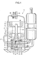
- Fig. 1 is a vertical cross sectional side view of an enclosed type electrically driven compressor C to which a synchronous induction motor is applied;
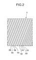
- Fig. 2 is a plan view of a rotor shown in Fig. 1;
- Fig. 3 is a horizontal cross sectional top view of the rotor shown in Fig. 1;
- Fig. 4 is a vertical cross sectional side view of the rotor shown in Fig. 1;
- Fig. 5 is a horizontal cross sectional top view of the rotor;
- Fig. 6. is a view showing a magnetomotive force generated by the rotor;
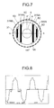
- Fig. 7 is a horizontal cross sectional top view of a rotor in accordance with the present invention;
- Fig. 8 is a view showing a magnetomotive force generated by the rotor in accordance with the present invention;
- Fig. 9 is a schematic view describing an ideal magnetomotive force generated by a synchronous induction motor provided with a permanent magnet having a two-pole structure;
- Fig. 10 is a view of an electric circuit of a synchronous induction motor of a single-phase two-pole type; and
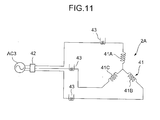
- Fig. 11 is a view of an electric circuit of a synchronous induction motor of a three-phase two-pole type.
-
- Next, a description will be given in detail of an embodiment in accordance with the present invention with reference to the accompanying drawings. In each of the drawings, reference numeral 1 denotes a sealed vessel. A
synchronous induction motor 2 is received in an upper side within the sealed vessel 1, and acompressor 3 rotated by thesynchronous induction motor 2 is received in a lower side within the sealed vessel 1. The sealed vessel 1 is structured such as to be previously separated into two sections, receive thesynchronous induction motor 2 and thecompressor 3 therein and be sealed by a high-frequency welding or the like. In this case, as an enclosed type electrically driven compressor C, there are listed up a rotor compressor, a reciprocal compressor, a scroll compressor and the like. - The
synchronous induction motor 2 is constituted by astator 4 made by a single-phase two -pole structure and fixed to an inner wall of the sealed vessel 1, and arotor 5 supported to an inner side of thestator 4 so as to freely rotate around arotary shaft 6. Further, thestator 4 is provided with astator coil 7 applying a rotary magnetic field to therotor 5. - The
compressor 3 is provided with a firstrotary cylinder 9 and a secondrotary cylinder 10 which are sectioned by anintermediate partition plate 8.Eccentric portions rotary shaft 6 are mounted to therespective cylinders eccentric portions -
Reference numeral cylinders first roller 13 and thesecond roller 14 respectively rotate within the cylinders due to rotation of theeccentric portions Reference numerals first frame body 15 forms a closed compression space between thefirst frame body 15 and theintermediate partition plate 8, and thesecond frame body 16 forms a closed compression space of thecylinder 10 between thesecond frame body 16 and theintermediate partition plate 8 in the same manner. Further, thefirst frame body 15 and thesecond frame body 16 are respectively provided with bearingportions rotary shaft 6. -
Reference numerals discharge mufflers first frame body 15 and thesecond frame body 16. In this case, thecylinder 9 and thedischarge muffler 19 are communicated with each other by a discharge hole (not shown) provided in thefirst frame body 15, and thecylinder 10 and thedischarge muffler 20 are also communicated with each other by a discharge hole (not shown) provided in thesecond frame body 16.Reference numeral 21 denotes a bypass pipe provided in an outer portion of the sealed vessel 1. Thebypass pipe 21 is communicated with an inner portion of thedischarge muffler 20. - Further,
reference numeral 22 denotes a discharge pipe provided on the sealed vessel 1, andreference numerals cylinders reference numeral 25 denotes a sealed terminal. The sealedterminal 25 is structured such as to supply an electric power to thestator coil 7 of thestator 4 from an external portion of the sealed vessel 1 (a lead wire connecting the sealedterminal 25 to thestator coil 7 is not illustrated). - Further,
reference numeral 26 denotes a rotor iron core. Therotor iron core 26 is structured such that a plurality of rotor steel plates obtained by punching an electromagnetic steel plate having a thickness between 0.3 mm and 0.7 mm (not shown) in a predetermined shape are laminated and are caulked with each other so as to be integrally laminated (in this case, it is possible to integrally form in accordance with a welding in place of the caulking).Reference numerals rotary iron core 26. The flatend surface members rotor iron core 26 together with the upperend surface member 66 by arivet 51. - The
rotor 5 is constituted by arotor yoke portion 5A, a cage-type secondaryelectric conductor 5B provided in a peripheral portion of therotary yoke portion 5A, and apermanent magnet 31 inserted to therotor yoke portion 5A. A plurality of cage-type secondaryelectric conductors 5B are provided in the peripheral portion of therotor yoke portion 5A, and an aluminum die casting is injection molded in a cylindrical hole (not shown) formed in a cage shape around an extending direction of therotary shaft 6. Both ends of the cage-typesecondary conductor 5B are formed in a so-called skewed structure which is inclined in a spiral shape having a predetermined angle in a circumferential direction of therotary shaft 6. - Further,
engagement holes rotor yoke portion 5A so as to be in parallel and oppose to both sides of therotary shaft 6, and theengagement holes rotor yoke portion 5A to another end. Each of theengagement holes permanent magnet 31 mentioned below, theengagement holes rotary shaft 6, and the engagement holes 5D and 5D are provided in an apart side of therotary shaft 6 with a predetermined interval. That is, theengagement holes rotor yoke portion 5A are positioned in a side of therotary shaft 6, the engagement holes 5D and 5D are positioned in an apart side of therotary shaft 6 on the basis of theengagement holes engagement holes - The
permanent magnet 31 is inserted to each of theengagement holes permanent magnet 31 is formed in a plate shape having a predetermined thickness and is inserted from one end of therotor yoke portion 5A to another end. Further, permanent magnets 31SA and 31NA having a large width are respectively inserted to both of theengagement holes rotor yoke portion 5A, and permanent magnets 31SB and 31NB having a small width are respectively inserted to both of the engagement holes 5D and 5D. In this case, a center in a width direction of each of thepermanent magnets 31, ... is arranged on a straight line vertically crossing a center of therotary shaft 6. Further, each of thepermanent magnets 31, ... employs a rare earth magnet having a largest magnetic flux density. - Further, the permanent magnets 31SA and 31SB and the permanent magnets 31NA and 31NB provided so as to oppose to the
rotary shaft 6 are inserted with different magnetic poles. In this case, the permanent magnets 31SA and 31SB inserted to one side (a right side in the drawing) of therotary shaft 6 are respectively set to the same S pole, and the permanent magnets 31NA and 31NB inserted to another side (a left side in the drawing) are respectively set to the same N pole (Fig. 7). That is, the permanent magnets 31SA and 31SB and the permanent magnets 31NA and 31NB are inserted toward an outer side in a circumferential direction of therotor 5 respectively in a two-pole structure comprising the different S pole and N pole, and are structured such as to apply a rotational force to therotor 5 by lines of magnetic force of amain coil 7A and anauxiliary coil 7B mentioned below. - In this case, Figs. 5 and 6 respectively show a structure of a rotor to which the permanent magnet having the two-pole structure is inserted, and a magnetomotive force generated thereby. In Fig. 5,
reference numeral 5 denotes a rotor, andreference numeral 31 denotes a permanent magnet. Therotor 5 is provided with thepermanent magnet 31 having the two-pole structure having the S pole in one side (the permanent magnets 31SA and 31SB in a right side in the drawing) and the N pole in another side (the permanent magnets 31NA and 31NB in a left side in the drawing). The permanent magnets 31SA and 31SB and the permanent magnets 31NA and 31NB are respectively inserted to therotor yoke portion 5A in a state of being. substantially closely attached to each other, and the S pole and the N pole of the permanent magnet 31 (the . permanent magnets 31SA and the permanent magnet 31NB, and the permanent magnet 31SB and the permanent magnet 31NA) are also inserted to therotor yoke portion 5A in a state of being substantially closely attached to each other. Fig. 6 is a view showing the magnetomotive force generated by the rotor 5 (in this case, the generated magnetomotive force is detected at a predetermined position of the rotor 5 (in this case, a position of anelectrical angle 0 degree in Fig. 5). In this case, in Fig. 6, a vertical axis shows a generated magnetomotive force and a horizontal axis shows an angle of rotation of therotor 5. Further, the generated magnetomotive force at a position at which the S pole and the N pole are balanced in a boundary between the S pole and the N pole (the positions having theelectrical angle 0 degree and 180 degrees) becomes 0 magnetomotive force. - Further, when rotating the
rotor 5 in a clockwise direction, the magnetomotive force generated by the permanent magnet 31NB is detected (in this case, the generated magnetomotive force directed to an upper portion in the drawing is detected). In accordance with further rotating therotor 5, the generated magnetomotive force becomes increased, and the generated magnetomotive force becomes a peak and the state is kept for a fixed angle of rotation (the magnetomotive force generated by the permanent magnet 31NB and the permanent magnet 31NA). Further, when further rotating therotor 5 and moving close to the permanent magnet 31SB (the position of theelectrical angle 180 degrees of therotor 5 in which the S pole and the N pole are balanced), the generated magnetomotive force of the S pole (the permanent magnet 31SB) is going to be small. Further, the generated magnetomotive force of the S pole (the permanent magnet 31SB) is detected at the same time when the electrical angle of therotor 5 is over 180 degrees (in this case, the generated magnetomotive force directed to a lower portion in the drawing is detected). In accordance with further rotating therotor 5, the generated magnetomotive force is going to be increased in a minus direction, so that the generated magnetomotive force becomes a peak and the state is kept for a fixed angle of rotation (the magnetomotive force generated by the permanent magnet 31SB and the permanent magnet 31SA). - Further, when further rotating the
rotor 5 so as to move close to the permanent magnet 31SA of the S pole (the position of the electrical angle O degree in which the S pole and the N pole are balanced), the magnetomotive force generated by the permanent magnet 31NB in the N pole is going to be reduced. Further, the electrical angle of therotor 5 is over theposition 0 degree (360 degrees), the magnetomotive force generated by the N pole (the permanent magnet 31NB) is detected in the same manner as that mentioned above, and this operation is repeated. That is, therotor 5 generates the magnetomotive force formed in a substantially rectangular shape in which the generated magnetomotive force in the S pole and the generated magnetomotive force in the N pole are continuously formed). - In the case of using the synchronous induction motor having the two-pole structure, since the S pole and the N pole are adjacent to each other, an interval between the generated magnetomotive forces having the different electrical angles is substantially continuous as is known from Fig. 6 and no gap exists. Accordingly, the driving force is applied to the
rotor 5 in a reverse direction due to the generated magnetomotive forces of the adjacent different permanent magnets, and an output property (a pullout torque) is reduced, so that it is impossible to secure a large reluctance torque. Accordingly, it is required to further improve a high efficiency of a commercial power source drive by using the synchronous induction motor having the two-pole structure. - Accordingly, a description will be given next of a synchronous induction motor having a two-pole structure intending to increase an efficiency. Fig. 8 shows a magnetomotive force generated by the
rotor 5 to which thepermanent magnet 31 having the two-pole structure is inserted. Further, reference symbol S in a right side in Fig. 7 denotes the S pole of the permanent magnets 31SA and 31SB, and reference symbol N in a left side denotes the N pole of the permanent magnets 31NA and 31NB. Fig. 8 shows a generated magnetomotive force detected at a predetermined position (in this case, a position having anelectrical angle 0 degree in Fig. 7) of therotor 5. In this case, in the drawing, a vertical axis shows the generated magnetomotive force, and a horizontal axis shows an angle. of rotation. When rotating therotor 5 in a clockwise direction, the generated magnetomotive force is not detected until the permanent magnet 31NA reaches the position having theelectrical angle 0 degree, and a state that the generated magnetomotive force is not detected is kept until the permanent magnet 31NA reaches theelectrical angle 0 degree (in this case, the electrical angle of therotor 5 is about 10 degrees). - Further, when the permanent magnet 31NA reaches the position having the
electrical angle 0 degree, the generated magnetomotive force is detected (in this case, the generated magnetomotive force is shown in an upper portion of the drawing). In accordance with further rotating therotor 5, the generated magnetomotive force is going to be increased, and when the permanent magnet 31NA moves close to theelectrical angle 0 degree in parallel, the generated magnetomotive force becomes a peak and the state is kept for a fixed angle of rotation. Further, when further rotating therotor 5, the permanent magnet 31NB reaches the position of theelectrical angle 0 degree in this case and the generated magnetomotive force of thepermanent magnet 31 NB is detected, and thereafter, the generated magnetomotive force is further increased, and when the permanent magnet 31NB moves close to the position having theelectrical angle 0 degree in parallel, the generated magnetomotive force becomes a peak and the state is kept for a fixed angle of rotation. - Further, the generated magnetomotive force in which the electrical angle of the
rotor 5 is until 90 degrees to 180 degrees becomes a generated magnetomotive force until an electrical angle 90 degrees to 0 degree reverse to the generated magnetomotive force until theelectrical angle 0 degree to 90 degrees mentioned above. Further, in the generated magnetomotive force from theelectrical angle 180 degrees of therotor 5 to 360 degrees (0 degree), since a polarity of the permanent magnets 31SA and 31SB inserted to another side of therotor 5 becomes the S pole, the generated magnetomotive force is generated in an opposite side to the generated magnetomotive force in the N pole side (theelectrical angle 0 degree to 180 degrees) (the generated magnetomotive force in this case is detected in a lower side in the drawing). - On the contrary, since the generated magnetomotive force in the case of only inserting the permanent magnets 31SA and 31NA to the
engagement hole 5C without inserting the permanent magnets 31SB and 31NB to theengagement hole 5D is formed in a shape in which a predetermined rotational angle portion of therotor 5 becomes flat (a rectangular wave shape) due to no magnetomotive force generated by the permanent magnets 31SB and 31NB, in addition that the permanent magnets 31SA and 31SB and the permanent magnets 31NA and 31NB are arranged at a predetermined interval, the permanent magnets 31SB and 31NB are structured such as to be narrower than the permanent magnets 31SA and 31NA. Accordingly, the magnetomotive force generated by the permanent magnets 31SB and 31NB is overlapped with the flat portion of the magnetomotive force generated by the permanent magnets 31SA and 31NA due to the rotation of therotor 5 so as to form two stages and be distributed in a stepped chevron shape having two stages, thereby being made similar to a generated magnetomotive force having an ideal sine wave shape. - Next, a description will be given of an ideal generated magnetomotive force of the synchronous induction motor provided with the permanent magnet having the two-pole structure with reference to Fig. 9. In the case of the synchronous induction motor provided with the permanent magnet having the two-pole structure, the generated magnetomotive force is ideally structured such that no generated magnetomotive force exists in sections of the electrical angles of the
rotor 5 between 0 degree and 10 degrees and between 170 degrees and 180 degrees, and in a section of the electrical angle between 10 degrees and 170 degrees, the sine wave in which a magnitude of the generated magnetomotive force in an upward direction becomes a peak (a position of a line A in the drawing) at a time when the electromagnetic angle of therotor 5 is 90 degrees is formed (in this case, the N pole side). Further, the generated magnetomotive force is ideally structured such that in the S pole side, no generated magnetomotive force exists in sections of the electrical angles of therotor 5 between 180 degrees and 190 degrees and between 350 degrees and 360 degrees, and in a section of the electrical angle between 190 degrees and 350 degrees, the sine wave in which a magnitude of the generated magnetomotive force in a downward direction becomes a peak at a time when the electromagnetic angle of therotor 5 is 270 degrees is formed. - In this case, since the generated magnetomotive force does not exist between the sections of the electrical angle of the
rotor 5 between 0 degree and 10 degrees and between 170 degrees and 180 degrees, and the generated magnetomotive force waveform distribution of therotor 5 in the sections of the electrical angles between 10 degrees and 170 degrees and between 190 degrees and 350 degrees is formed in the sine wave shape, it is possible to effectively make good use of the reluctance so as to restrict a rotational torque unevenness of therotor 5. Accordingly, since it is possible to smoothly rotate the synchronous induction motor, it is possible to achieve a high efficiency and a high torque. That is, in accordance with the present invention, the permanent magnets 31SA and 31SB and the permanent magnets 31NA and 31NB are arranged in therotor 5 at a predetermined interval and the permanent magnets 31SB and 31NB are structured such as to be narrower than the permanent magnets 31SA and 31NA, whereby the magnetomotive force generated by therotor 5 is distributed in the stepped chevron shape having the two stages similar to the sine wave. Accordingly, it is possible to form the ideal generated magnetomotive force of the synchronous induction motor. - Comparing the
synchronous induction motor 2 having the structure mentioned above with the conventional synchronous induction motor, the following Table 1 is obtained.COMPARATIVE DATA CONVENTIONAL SHAPE SHAPE OF PRESENT INVENTION POWER SOURCE [Hz-V] 60Hz-230V 60Hz-230V OPERATION TORQUE[Nm] 3.4 3.4 INPUT [W] 1466 1418(Δ48W) EFFICIENCY [%] 87.4 90.4(+3%) PULLOUT TORQUE [Nm] 4.9 6.6(+34.7%) TOTAL FLUX AMOUNT [%] 100 91 * Measure only the pullout torque mentioned above in 60 Hz-208V. * Total flux amount: describe a value on the assumption that the conventional shape is set to 100. - It is generally said that when an area of a generated magnetomotive force (an amount of flux) is great, an operation performance (an operation efficiency) and an output property (a pullout torque) are improved. In accordance with Table 1, in the case of the same power source 60 Hz/230 V and operation torque 3.4 Nm, the input of the present invention is 1418 W lower than 1466 W in the conventional one, and the efficiency of the present invention is 90.4 % better than 87.4 % in the conventional one. Further, the pullout torque (the peak torque) is 6.6 Nm better than 4.9 Nm in the conventional one, and the total flux amount of the present invention is 91 % with respect to 100 % in the conventional one. As is known from the table, the shape of the generated magnetomotive force in accordance with the present invention in which the total flux amount is small has a great and excellent property in both of the operation efficiency and the output property.
- Accordingly, it is known that the operation property of the
synchronous induction motor 2 is improved because the shape of the magnetomotive force generated by therotor 5 from thestator 4 side is formed in a substantially sine wave shape (distributed in the step manner). Further, it is known that the output property (the pullout torque) is obtained because the generated magnetomotive force does not exist (exists a little) in the sections of the electrical angle between 0 degree and 10 degrees and between 170 degrees and 180 degrees, in the distribution of the generated magnetomotive force corresponding to one pole of therotor 5, and the section of the rotational angle largely contribute to improve the reluctance, thereby largely increasing the output property (the pullout torque). - As mentioned above, it is possible to largely improve the operation property and the output property by taking the arrangement of the
permanent magnet 31 and the like into consideration, even when the total flux amount is small. Further, in the case of reducing the total flux amount, since it is possible to make thepermanent magnet 31 inserted to therotor 5 small, it is possible to reduce a cost. - On the contrary, Fig. 10 shows an electric circuit diagram of the
synchronous induction motor 2 of a single-phase two-pole. In Fig. 10, thesynchronous induction motor 2 is provided with thestator coil 7 comprising themain coil 7A and theauxiliary coil 7B. A series circuit constituted by anoperation condenser 32 connected in series, astart condenser 33 and astart switch 33A which are connected in parallel to theoperation condenser 32 is connected to one of theauxiliary coil 7B. In this case,reference numeral 34 denotes an electric current sensing type line electric current detector,reference numeral 34A denotes a protecting switch shutting a power supply to thestator coil 7 in the case that a previously set predetermined electric current is detected by the line electriccurrent detector 34, and reference symbol AC2 denotes a single-phase alternating commercial power source. - On the basis of the structure mentioned above, a description will be given next of an operation of the
synchronous induction motor 2. In this case, it is assumed that thestart switch 33A is closed in a state that thesynchronous induction motor 2 stops. Further, when the power switch (the protectingswitch 34A) is closed, the electric current starts flowing to themain coil 7A and theauxiliary coil 7B from the single-phase alternating commercial power source AC2, and since the parallel circuit constituted by thestart condenser 33 and theoperation condenser 32 is connected to theauxiliary coil 7B, therotor 5 starts in a predetermined rotating direction due to an application of a desired start torque. - At this time, since the generated magnetomotive force distributed in the stepped chevron shape having two stages similar to the sine wave is formed in the
rotor 5, therotor 5 reacts to the electric current flowing to thestator coil 7 and a start operation of thesynchronous induction motor 2 is executed. Further, when a rotational speed of therotor 5 is increased to a predetermined rotational number (in this case, about 80 % of a synchronous rotational number), thestart switch 33A is opened, thestart condenser 33 is broken out from the circuit, and thesynchronous induction motor 2 is operated only by theoperation condenser 32. Accordingly, at a time of operating thesynchronous induction motor 2 after a starting time immediately when thepower source switch 34A is closed until the synchronous operation is executed, it is possible to drive at a high efficiency and a high torque due to the generated magnetomotive force similar to the sine wave of the stepped chevron shape applied by thepermanent magnet 31. - In the above enbodiment, the generated magnetomotive force does not exist between the sections of the electrical angle of the
rotor 5 between 0 degree and 10 degrees and between 170 degrees and 180 degrees. But the above effects can be obtained in case of the value of the generated magnetmotive force is equal to or less than 10 % of the peak value in the above range of the electrical angle. - As mentioned above, the generated magnetomotive force corresponding to one pole of the
permanent magnet 31 inserted to therotor 5 is concentrated in the sine wave shape by being set to be equal to or less than 10 % of the peak value in the electrical angle between 0 degree and 10 degrees and between 170 degrees and 180 degrees and being distributed in the step shape in the electrical angle between 10 degrees and 170 degrees. Accordingly, it is possible to effectively make good use of the reluctance torque so as to restrict the rotational torque unevenness of therotor 5, and it is possible to largely increase a preferable output property (pullout torque). Therefore, it is possible to operate thesynchronous induction motor 2 at a high efficiency and at a high torque. - Further, since the cage-type secondary
electric conductor 5B of therotor 5 is made in the skewed structure, it is possible to easily execute a self start by the single-phase power source in the same manner as that of the conventional synchronous induction motor. Accordingly, it is possible to easily execute a self start of thesynchronous induction motor 2 even by the single-phase power source. Further, since thepermanent magnet 31 is set to the rare earth magnet, it is possible to significantly increase the magnetic flux density of thepermanent magnet 3. - When mounting the
synchronous induction motor 2 having the structure mentioned above to the compressor of the air conditioner, the electric refrigerator or the like, it is possible to achieve a widely low energy structure and it is possible to reduce a cost. Accordingly, it is possible to develop a commercial product corresponding to the energy regulation or the like. - Next, Fig. 11 shows an electric circuit diagram of the
synchronous induction motor 2A having three phases and two poles. In Fig. 11, asynchronous induction motor 2A is provided with a three-phase stator coil 41 constituted by acoil 41A, acoil 41B and acoil 41C. Each of thecoil 41A, thecoil 41B and thecoil 41C of thestator coil 41 is connected to a three-phase alternating commercial power source AC3 via apower source switch 42. In this case,reference numeral 43 denotes an electric current sensing type line electric current detector for detecting a line electric current. The line electriccurrent detector 43 is provided in each of wires connected to therespective coils stator coil 7 in the case of sensing a previously set predetermined electric current by the line electriccurrent detector 43. - Next, a description will be given of an operation of the
synchronous induction motor 2. When thepower switch 42 is closed, the three-phase electric current flows through thecoils rotor 5 starts in a predetermined rotational direction due to the generated magnetomotive force. At this time, since the generated magnetomotive force distributed in the two-stage stepped chevron shape similar to the sine wave is formed in therotor 5 in the same manner as mentioned above, therotor 5 reacts to the electric current flowing to thestator coil 41 and the start operation of thesynchronous induction motor 2A is executed. - Further, since the three-phase sine wave alternating current (the three-phase alternating commercial power source AC) is applied to the
stator coil 41 so as to rotate therotor 5 due to the magnetomotive force generated by thepermanent magnet 31, it is possible to execute the self start in the same manner as that of the conventional synchronous induction motor. Further, at a time of the operation, it is possible to execute a synchronous operation due to the magnetomotive force generated by thepermanent magnet 31 inserted to therotor 5. - As mentioned above, the three-phase two-pole
synchronous induction motor 2A also makes the generated magnetomotive force corresponding to one pole of thepermanent magnet 31 inserted to therotor 5 equal to or less than 10 % of the peak value in the range of the electrical angle between 0 degree and 10 degrees and between 170 degrees and 180 degrees in the same manner as mentioned above, and the generated magnetomotive force in the range of the electrical angle between 10 degrees and 170 degrees is distributed in the step shape so as to be concentrated in the sine wave shape. Accordingly, as well as the single-phase two-polessynchronous induction motor 2, in the three-phase two-polesynchronous induction motor 2A, it is possible to effectively make good use of the reluctance torque so as to restrict the rotational torque unevenness of therotor 5 and it is possible to largely increase a preferable output property (a pullout torque). Accordingly, it is possible to operate thesynchronous induction motor 2A at a high efficiency and at a high torque. - In this case, in the embodiment, the structure is made such that the one-pole
permanent magnet 31 in one side of therotor 5 is constituted by two permanent magnets 31SA and 31SB and the one-polepermanent magnet 31 in another side is constituted by two permanent magnets 31NA and 31NB, however, the structure is not limited to this, and even when plural sheets ofpermanent magnets 31 are provided in one pole of one side in therotor 5 and plural sheets ofpermanent magnets 31 are provided in one pole of another side, thereby distributing the generated magnetomotive force in the ranges of the electrical angle between 10 degrees and 170 degrees and between 190 degrees and 350 degrees in a step shape having two stages or more and further making it similar to the sine wave shape, the present invention is effective. - As described in detail above, in accordance with the present invention, since in the synchronous induction motor having the stator provided with the stator winding, the rotor rotating within the stator, the cage-type secondary electric conductor provided in the peripheral portion of the rotor yoke portion constituting the rotor, and the permanent magnet inserted into the rotor yoke portion and having the two-pole structure, the magnetomotive force generated by one pole of the rotor is set to the value equal to or less than 10 % of a peak value in the predetermined range near the
electrical angle 0 degree or 180 degrees, it is possible to concentrate the magnetomotive force generated by the rotor to a range between 10 degrees and 170 degrees which corresponds to the other range than the electrical angles 0-10 degrees and 170-180 degrees by setting the range equal to or less than 10 % the electrical angles 0-10 degrees and 170-180 degrees. Accordingly, since it is possible to secure a great reluctance torque, it is possible to achieve a high efficiency and a high torque of the synchronous induction motor. - Further, in accordance with the present invention, in addition to the above, since the magnetomotive forces generated by the rotor in the other range of the electrical angle than the range equal to or less than 10 % are distributed in a sine wave shape, it is possible to smoothly rotate the rotor. Accordingly, it is possible to make good use of a reluctance torque.
- Further, when the magnetomotive forces generated by the rotor in the other range of the electrical angle than the range equal to or less than 10 % are distributed in a step-like chevron shape having two steps or more, it is possible to make the magnetomotive force generated by the rotor having the permanent magnet having the two-pole structure inserted into the rotor yoke portion similar to a sine wave. Accordingly, it is possible to achieve a high efficiency and a high torque without largely deteriorating an effect of the magnetomotive force generated by the rotor.
- In particular, if the generated magnetomotive force is, for example, formed in the shape distributed in a step-like chevron shape having two steps or more, it is possible to further improve an effectiveness of a high efficiency and a high torque.
- Further, in accordance with the present invention, since the synchronous induction motor mentioned above is mounted on the compressor, it is possible to realize a low energy structure, for example, by using the compressor in the air conditioning device or the electric refrigerator. Accordingly, it is possible to develop a commercial product, for example, corresponding to a recent energy regulation or the like.
Claims (9)
- A synchronous induction motor comprising:wherein the magnetomotive force generated by one pole of said rotor is set to a value equal to or less than 10 % of a peak value in a predetermined range near an electrical angle 0 degree or 180 degrees.a stator provided with a stator winding;a rotor rotating within said stator;a cage-type secondary electric conductor provided in a peripheral portion of a rotor yoke portion constituting said rotor; anda permanent magnet inserted into the rotor yoke portion and having a two-pole structure,
- A synchronous induction motor as claimed in claim 1,
wherein said range equal to or less than 10 % is set to electrical angles 0-10 degrees and 170-180 degrees. - A synchronous induction motor as claimed in claim 1 or 2, wherein the magnetomotive forces generated by said rotor in the other range of the electrical angle than said range equal to or less than 10 % are distributed in a sine wave shape.
- A synchronous induction motor as claimed in claim 1 or 2, wherein the magnetomotive forces generated by said rotor in the other range of the electrical angle than said range equal to or less than 10 % are distributed in a step-like chevron shape having two steps or more.
- A synchronous induction motor as claimed in claim 1, 2, 3 or 4, wherein the synchronous induction motor is mounted on a compressor.
- A synchronous induction motor as claimed in claim 5,
wherein the compressor is used in an air conditioning device or an electric refrigerator. - A rotor for use in a synchronous induction motor according to any preceding claim having a permanent magnet inserted therein which has a two-pole structure, said magnet being configured such that a magnetomotive force generated by one pole of said rotor is set to a value equal or less than 10% of a peak value in a predetermined angle near an electrical angle 0 degree or 180 degrees.
- An induction motor comprising:a stator;a rotor for rotating within said stator;an arrangement of permanent magnets disposed within the rotor comprising first and second pairs of magnets, each pair of magnets disposed either side of an axis of rotation of said rotor, wherein said first pair of magnets is arranged outside of said second pair of magnets so as to align their magnetic poles and form a two-pole structure.
- An induction motor according to claim 8, wherein each of said first pair of magnets are smaller than each of said second pair of magnets.
Applications Claiming Priority (2)
| Application Number | Priority Date | Filing Date | Title |
|---|---|---|---|
| JP2001021862A JP3676242B2 (en) | 2001-01-30 | 2001-01-30 | Induction synchronous motor |
| JP2001021862 | 2001-01-30 |
Publications (1)
| Publication Number | Publication Date |
|---|---|
| EP1227568A1 true EP1227568A1 (en) | 2002-07-31 |
Family
ID=18887350
Family Applications (1)
| Application Number | Title | Priority Date | Filing Date |
|---|---|---|---|
| EP01310892A Withdrawn EP1227568A1 (en) | 2001-01-30 | 2001-12-24 | Synchronous induction motor |
Country Status (4)
| Country | Link |
|---|---|
| US (1) | US6700270B2 (en) |
| EP (1) | EP1227568A1 (en) |
| JP (1) | JP3676242B2 (en) |
| CN (1) | CN1237689C (en) |
Cited By (2)
| Publication number | Priority date | Publication date | Assignee | Title |
|---|---|---|---|---|
| WO2005006520A1 (en) * | 2003-07-09 | 2005-01-20 | Matsushita Electric Industrial Co. Ltd. | Syncronous induction motor and electric hermetic compressor using the same |
| EP1615328A1 (en) * | 2004-07-08 | 2006-01-11 | LG Electronics Inc. | Induction motor controller |
Families Citing this family (25)
| Publication number | Priority date | Publication date | Assignee | Title |
|---|---|---|---|---|
| CN100414814C (en) * | 2003-03-25 | 2008-08-27 | 乐金电子(天津)电器有限公司 | Rotor of synchronous magneto resistance motor |
| US6791226B1 (en) * | 2003-09-10 | 2004-09-14 | Wavecrest Laboratories, Llc | Multiphase motor winding topology and control |
| KR100593542B1 (en) * | 2004-07-08 | 2006-06-28 | 엘지전자 주식회사 | Drive of Capacitor Driven Hybrid Induction Motor |
| CA2579663C (en) * | 2004-09-13 | 2010-10-26 | Siemens Energy & Automation, Inc. | System and method for managing air flow in a motor |
| DE102005060118A1 (en) * | 2004-12-20 | 2006-07-06 | Danfoss Compressors Gmbh | Rotor for an electric motor |
| DE102005060117A1 (en) * | 2004-12-20 | 2006-07-06 | Danfoss Compressors Gmbh | Rotor with cover plate for securing a magnet in the rotor |
| DE102005060116A1 (en) * | 2004-12-20 | 2006-07-06 | Danfoss Compressors Gmbh | Rotor for an electric motor |
| KR100631551B1 (en) * | 2004-12-21 | 2006-10-09 | 엘지전자 주식회사 | Dual Magnet Hybrid Induction Motor |
| US20070132330A1 (en) * | 2005-12-12 | 2007-06-14 | Fei Renyan W | Fan assemblies employing LSPM motors and LSPM motors having improved synchronization |
| WO2007133500A2 (en) * | 2006-05-10 | 2007-11-22 | Jones Robert M | Electric machine having segmented stator |
| US7772736B2 (en) | 2006-06-09 | 2010-08-10 | Hitachi Appliances, Inc. | Permanent magnet synchronous motor, rotor of the same, and compressor using the same |
| US7932658B2 (en) * | 2007-03-15 | 2011-04-26 | A.O. Smith Corporation | Interior permanent magnet motor including rotor with flux barriers |
| WO2008137709A2 (en) * | 2007-05-04 | 2008-11-13 | A. O. Smith Corporation | Interior permanent magnet motor and rotor |
| US8102091B2 (en) * | 2008-07-30 | 2012-01-24 | Regal Beloit Epc Inc. | Interior permanent magnet motor including rotor with unequal poles |
| BRPI0900907A2 (en) * | 2009-03-31 | 2010-12-14 | Whirlpool Sa | synchronous and induction motor |
| EP2415144A4 (en) * | 2009-04-03 | 2016-07-06 | Jones Robert M | ENGINE WITH THREE STACKS COOLED BY OVERMOLDED LIQUID |
| DE102011119922A1 (en) * | 2011-11-28 | 2013-05-29 | Kienle + Spiess Gmbh | Lamella stacks for rotors and / or stators of electric motors and generators, rotor with such a fin stack and method for producing a rotor and / or stator |
| US9906108B2 (en) | 2012-11-01 | 2018-02-27 | General Electric Company | Sensorless electric machine |
| US9871418B2 (en) | 2012-11-01 | 2018-01-16 | General Electric Company | Sensorless electric machine |
| US9941775B2 (en) * | 2012-11-01 | 2018-04-10 | General Electric Company | D-ring implementation in skewed rotor assembly |
| MX355454B (en) | 2013-03-14 | 2018-04-18 | Emerson Electric Co | Rotors and stators for dynamoelectric machines. |
| US9906082B2 (en) | 2013-09-06 | 2018-02-27 | General Electric Company | Electric machine having reduced torque oscillations and axial thrust |
| CN104779722B (en) * | 2015-04-28 | 2017-06-23 | 哈尔滨工业大学 | A kind of rotor structure of high-speed permanent magnet motor |
| CN109715945B (en) * | 2016-10-07 | 2021-07-23 | 比泽尔制冷设备有限公司 | Semi-hermetic refrigerant compressor |
| US12051949B2 (en) * | 2021-01-19 | 2024-07-30 | Mahle International Gmbh | Asymmetrical skewed rotor |
Citations (4)
| Publication number | Priority date | Publication date | Assignee | Title |
|---|---|---|---|---|
| GB677941A (en) * | 1949-06-01 | 1952-08-27 | British Thomson Houston Co Ltd | Improvements in and relating to dynamo-electric machines |
| DE1203378B (en) * | 1960-09-13 | 1965-10-21 | Allis Chalmers Mfg Co | Self-starting synchronous reluctance motor |
| US4403161A (en) * | 1977-06-24 | 1983-09-06 | Hitachi, Ltd. | Permanent magnet rotor |
| EP1043827A2 (en) * | 1999-03-30 | 2000-10-11 | Kabushiki Kaisha Toshiba | Rotor for permanent magnet type rotating machine |
Family Cites Families (4)
| Publication number | Priority date | Publication date | Assignee | Title |
|---|---|---|---|---|
| DE3429813A1 (en) * | 1984-08-14 | 1986-02-27 | Landert-Motoren-AG, Bülach, Zürich | Permanent-magnet synchronous motor with asynchronous starting |
| DE3522525A1 (en) * | 1985-06-24 | 1987-01-02 | Siemens Ag | Armature-feedback compensated reluctance motor |
| JPH07274460A (en) * | 1994-03-30 | 1995-10-20 | Kinshiro Naito | Synchronous machine |
| JP2000134891A (en) * | 1998-10-28 | 2000-05-12 | Okuma Corp | Synchronous motor and its control device |
-
2001
- 2001-01-30 JP JP2001021862A patent/JP3676242B2/en not_active Expired - Fee Related
- 2001-08-31 CN CN01125235.9A patent/CN1237689C/en not_active Expired - Fee Related
- 2001-12-05 US US10/002,619 patent/US6700270B2/en not_active Expired - Lifetime
- 2001-12-24 EP EP01310892A patent/EP1227568A1/en not_active Withdrawn
Patent Citations (4)
| Publication number | Priority date | Publication date | Assignee | Title |
|---|---|---|---|---|
| GB677941A (en) * | 1949-06-01 | 1952-08-27 | British Thomson Houston Co Ltd | Improvements in and relating to dynamo-electric machines |
| DE1203378B (en) * | 1960-09-13 | 1965-10-21 | Allis Chalmers Mfg Co | Self-starting synchronous reluctance motor |
| US4403161A (en) * | 1977-06-24 | 1983-09-06 | Hitachi, Ltd. | Permanent magnet rotor |
| EP1043827A2 (en) * | 1999-03-30 | 2000-10-11 | Kabushiki Kaisha Toshiba | Rotor for permanent magnet type rotating machine |
Cited By (5)
| Publication number | Priority date | Publication date | Assignee | Title |
|---|---|---|---|---|
| WO2005006520A1 (en) * | 2003-07-09 | 2005-01-20 | Matsushita Electric Industrial Co. Ltd. | Syncronous induction motor and electric hermetic compressor using the same |
| US7071650B2 (en) | 2003-07-09 | 2006-07-04 | Matsushita Electric Industrial Co., Ltd. | Synchronous induction motor and electric hermetic compressor using the same |
| CN1698251B (en) * | 2003-07-09 | 2010-11-03 | 松下电器产业株式会社 | Synchronous induction motor and electric hermetic compressor using the motor |
| EP1615328A1 (en) * | 2004-07-08 | 2006-01-11 | LG Electronics Inc. | Induction motor controller |
| US7084599B2 (en) | 2004-07-08 | 2006-08-01 | Lg Electronics Inc. | Induction motor controller |
Also Published As
| Publication number | Publication date |
|---|---|
| JP2002233087A (en) | 2002-08-16 |
| US20020140307A1 (en) | 2002-10-03 |
| CN1237689C (en) | 2006-01-18 |
| US6700270B2 (en) | 2004-03-02 |
| JP3676242B2 (en) | 2005-07-27 |
| CN1368784A (en) | 2002-09-11 |
Similar Documents
| Publication | Publication Date | Title |
|---|---|---|
| US6700270B2 (en) | Synchronous induction motor | |
| EP1261104A2 (en) | Permanent magnet type rotating electrical machine | |
| US7669311B2 (en) | Method of manufacturing a core for an electrical machine | |
| US6737783B2 (en) | Sealed motor compressor | |
| JP3828015B2 (en) | Permanent magnet type motor, method of manufacturing permanent magnet type motor, compressor and refrigeration cycle apparatus | |
| CN102007669B (en) | Permanent magnet motor, hermetic compressor and refrigeration cycle device | |
| JP6942246B2 (en) | Rotors, motors, compressors and air conditioners | |
| US11258319B2 (en) | Motor, compressor, and air conditioning apparatus | |
| JP2003061283A (en) | Rotary electric machine rotor, stator, electric motor, compressor, refrigeration cycle, rotor electric machine rotor manufacturing method | |
| JP3772608B2 (en) | Rotating electric machine and compressor | |
| JPH10309050A (en) | Compressor | |
| CN101151781A (en) | Single-phase motor and hermetic compressor | |
| CN104823372A (en) | electric motor | |
| US6508636B2 (en) | Freon compressor | |
| JP2017034819A (en) | Permanent magnet synchronous machine, compressor and air conditioner | |
| WO2023032134A1 (en) | Electric motor, compressor, and refrigeration cycle device | |
| JP2003134773A (en) | Self-starting synchronous motor and compressor using the same | |
| JP2004357468A (en) | Electric motor | |
| JP2001275286A (en) | Hermetic electric compressor | |
| JP5354499B2 (en) | Permanent magnet motor, hermetic compressor, and refrigeration cycle apparatus | |
| JP3600121B2 (en) | Hermetic electric compressor | |
| JP2006345692A (en) | Permanent magnet motor | |
| JP2006034100A (en) | Permanent magnet motor | |
| JP7292424B2 (en) | Motors, compressors and air conditioners | |
| WO2023152891A1 (en) | Reluctance motor drive device, reluctance motor unit, compressor and air conditioner |
Legal Events
| Date | Code | Title | Description |
|---|---|---|---|
| PUAI | Public reference made under article 153(3) epc to a published international application that has entered the european phase |
Free format text: ORIGINAL CODE: 0009012 |
|
| AK | Designated contracting states |
Kind code of ref document: A1 Designated state(s): AT BE CH CY DE DK ES FI FR GB GR IE IT LI LU MC NL PT SE TR |
|
| AX | Request for extension of the european patent |
Free format text: AL;LT;LV;MK;RO;SI |
|
| 17P | Request for examination filed |
Effective date: 20021113 |
|
| AKX | Designation fees paid |
Designated state(s): ES FR IT |
|
| REG | Reference to a national code |
Ref country code: DE Ref legal event code: 8566 |
|
| 17Q | First examination report despatched |
Effective date: 20101220 |
|
| STAA | Information on the status of an ep patent application or granted ep patent |
Free format text: STATUS: THE APPLICATION IS DEEMED TO BE WITHDRAWN |
|
| 18D | Application deemed to be withdrawn |
Effective date: 20121122 |