Technical Field
The present invention relates to a coated optical fiber, an optical fiber
ribbon, and an optical fiber unit.
Background Art
An optical fiber is obtained by drawing an optical fiber preform having
at least a core and a cladding. Immediately after drawing, a coating is formed
around the outside of the glass optical fiber in order to protect and reinforce
the fiber and to give it flexibility, and for other purposes. It is known to form
at least two layered coatings, namely, a relatively soft (low Young's modulus)
primary coating which is in contact with the outer circumference of the glass
optical fiber and which has a buffering function, and a hard (high Young's
modulus) secondary coating formed on the outermost side and having a
protective function.
For example, a coated optical fiber is proposed in Japanese Patent
Application Laid open No. 9-5587, in which, by setting the extraction force (the
force necessary to pull a glass optical fiber out of the coated optical fiber which
is fixed from the outside), which force serves as the adhesion between the glass
optical fiber and the primary coating material forming the primary coating, at
90 g/mm to 180 g/mm, an adequate adhesion between the glass optical fiber
and the primary coating material is obtained, and partial delamination will
not occur at the interface between the glass optical fiber and the primary
coating material even when they are soaked in water for a long period.
However, when the extraction force corresponding to the adhesion
between the glass optical fiber and the primary coating material is set at 90
g/mm to 180 g/mm as described in the above publication, delamination
sometimes occurs at the interface between the glass and the coating material
in the coated optical fiber during or after the production of the coated optical
fiber: for example, during the period from drawing to cabling of the optical
fiber or during winding onto another bobbin. It is thought that minute foreign
materials such as chips of the optical fiber, adhering onto a pulley, on which
the coated optical fiber travels, due to static electricity or the like cause the
coated optical fiber to undergo large local deformation, and as a result,
delamination occurs at the interface between the glass optical fiber and the
primary coating.
An object of the present invention is to provide a coated optical fiber in
which such delamination during the period from drawing to cabling is
prevented.
A tapelike (ribbonlike) cable, which is formed by placing a plurality of
coated optical fibers in parallel in a plane and by forming a unitary jacket
around the coated optical fibers so as to coat them therein, is referred to as an
"optical fiber ribbon". When connecting optical fiber ribbons, it is necessary to
collectively remove the layers: the primary coating formed around the outside
of the glass optical fiber, and the unitary jacket. This operation is referred to
as "collective stripping of coatings". In this case, it is undesirable that the
coatings such as the primary coating or secondary or other coatings remain on
the surface of the glass optical fiber.
Another object of the present invention is to provide a coated optical
fiber which has an improved delamination resistance during drawing and
rewinding and whose collective strippability of coatings is not degraded when
it is used as a component of an optical fiber ribbon.
A further object of the present invention is to provide a coated optical
fiber which is assembled into a certain type of optical fiber unit or inserted
into a loose tube and is subjected to stripping of individual coated fiber when
connection is performed and in which the delamination resistance is increased
and stripping of individual coated fiber is easy.
A still further object of the present invention is to provide an optical
fiber ribbon in which the delamination resistance is increased and the
collective stripping of coatings is easy, or an optical fiber unit in which the
delamination resistance is increased and stripping of individual coated fiber is
easy.
Disclosure of Invention
In order to achieve the above objects, the present invention relates to:
Brief Description of the Drawings
Figure 1 is a graph showing the correlation among delamination, the
storage modulus E' of a primary coating, and the adhesion (between glass and
the primary coating), and the collective strippability of coatings of an optical
fiber ribbon. Figure 2 is a schematic sectional view showing an example of a
coated optical fiber according to the present invention. Figure 3 is a schematic
sectional view showing the structure of an optical fiber ribbon using the coated
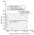
optical fiber of the present invention shown in Fig. 1. Figure 4 is a graph
showing the correlation among delamination, the storage modulus E' of the
primary coating, and the adhesion (between glass and the primary coating),
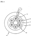
and the coating strippability. Figure 5 is a schematic sectional view showing
an example of an optical fiber unit using the coated optical fiber of the present
invention shown in Fig. 1.
Best Mode for Carrying out the Invention
The present inventors have found that regarding delamination the
storage modulus E' of a primary coating and the adhesion between a glass
optical fiber and the primary coating is correlated with the frequency of
delamination, and thus achieved the present invention.
Figure 2 is a schematic sectional view of an example of the present
invention. A primary coating 2, which has a storage modulus E' of 0.01
kg/mm2 to 0.5 kg/mm2 at 25°C and at a frequency of 110 Hz, is formed around
the outside of a glass optical fiber 1 having at least a core and a cladding, the
adhesion between the primary coating 2 and the glass optical fiber 1 is 10 g/cm
to 100 g/cm, and a secondary coating 3 is formed around the outside of the
primary coating 2, thereby constructing a coated optical fiber 4.
In the present invention, the storage modulus E' is obtained by
performing a calculation according to the following Equation (1), based on an
out-of-phase sinusoidal stress S = S0 exp[i(ωt+δ)] which is detected at one end
of a sample when a sinusoidal strain r = r0 exp(iωt) is applied as mechanical
vibration to the other end:
E* = S/r
= S0 exp[i(ωt+δ)]/r0 exp(iωt)
= S0/r0•cos δ+iS0/r0•sinδ
= E'+i•E"
where E* represents the complex viscoelasticity, E' represents the storage
modulus, E" represents the loss viscoelasticity, S represents the stress, S0
represents the amplitude of the stress, r represents the strain, r0 represents
the amplitude of the strain, ω represents the angular velocity, t represents the
time, and δ represents the phase shift angle.
In Eq. (1), δ is a function of ω. In a quasi-static state, that is, when ω is
0, δ is 0, E" is 0, and the storage modulus E' corresponds to the so-called
Young's modulus.
A description will be given to explain why the storage modulus E' of the
primary coating resin serves as an index in the present invention.
In drawing of an optical fiber, a coated optical fiber is wound onto a
bobbin via some pulleys. When static electricity or the like causes foreign
materials to adhere to portions of the pulleys where the optical fiber travels,
delamination sometimes occurs at the interface between the glass and the
coating. Since the coated optical fiber is produced at high speed, the pulleys
are also rotated at high speed, and strain is rapidly applied to the coating, that
is, at a high strain rate.
Conventionally, the Young's modulus of the coating is measured based on
"the stress applied to extend the coating by 2.5% at a low strain rate of
approximately 1 mm/min". The Young's modulus found from the gradient of a
line which links a stress corresponding to a strain of 0 and a stress
corresponding to a strain of 2.5% is referred to as "2.5% secant Young's
modulus". From the viewpoint of measurement, this Young's modulus is used
instead of the Young's modulus at the origin where the strain is 0. However,
the present inventors have considered that it is more appropriate to use the
storage modulus E' as the index, which is the real part of the elastic modulus
in a high strain rate region, as opposed to using the Young's modulus
measured at a low strain rate which has been used in this technical field, such
as the 2.5% secant Young's modulus, because the resin used for the primary
coating or the like exhibits viscoelastic behavior, and have performed
investigations.
As a result, the present inventors found that there was a correlation
between the storage modulus E' at 25 °C and 110 Hz and the frequency of
delamination, which can be used for an index of elastic modulus in the high
strain rate region.
In the present invention, the adhesion is expressed as the force
necessary to separate a primary coating from a glass plate by 50 mm in a 180°
direction at a pulling rate of 200 mm/min after the primary coating is formed
on the surface of the glass plate. A more precise definition thereof will be
provided in the following examples.
Figure 1 is a graph which, based on the results of the following examples
of the present invention, shows the proper ranges of the storage modulus E'
(25°C, 110 Hz) of a primary coating of an optical fiber ribbon according to the
present invention, and the adhesion between a glass optical fiber and the
primary coating. As shown in Fig. 1, when the storage modulus E' of the
primary coating at 25°C and 110 Hz is within the range of 0.01 kg/mm2 to 0.5
kg/mm2 and the adhesion is within the range of 10 g/cm to 100 g/cm,
delamination does not occur at the interface between the glass optical fiber
and the primary coating, and productivity and reliability of the coated optical
fiber are improved.
When the storage modulus E' of the primary coating is less than 0.01
kg/mm2, the primary coating is prone to internal rupture (voids) during
handling. Since the voids increase the transmission loss, for example, in a
low-temperature environment at -40°C, the formation of voids must be
prevented.
In contrast, when the storage modulus E' exceeds 0.5 kg/mm2 in the
coated optical fiber of the optical fiber ribbon, delamination is prone to occur at
the interface between the glass optical fiber and the primary coating. It is
supposed that, when the elastic modulus at a high strain rate is too high, a
large stress is produced at the interface between the glass optical fiber and the
primary coating when the coated optical fiber is deformed, causing the
likelihood of delamination to occur. A particularly preferable storage modulus
E' is within the range of 0.02 kg/mm2 to 0.3 kg/mm2 at 25°C and 110 Hz.
Delamination at the interface can be prevented by increasing the
adhesion between the glass optical fiber and the primary coating. When the
adhesion is excessively strong, however, the collective stripping of coatings is
difficult when connecting the optical fiber ribbon to other glass optical fibers.
Therefore, it is preferable that the adhesion be less than or equal to 100 g/cm.
In contrast, when the adhesion is less than 10 g/cm, delamination at the
interface between the glass optical fiber and the primary coating is likely to
occur. A particularly preferable adhesion is within the range of 15 g/cm to 75
g/cm.
Not all of the optical fibers are formed into a ribbon, but the optical
fibers may be assembled into a tight unit or may be inserted in a loose tube.
In these cases, it is only necessary to take stripping of individual coated fiber
into consideration. In such cases, both the storage modulus E' and the
adhesion between the glass optical fiber and the primary coating can be made
stronger than those in the above-described coated optical fiber for the fiber
ribbon, and this can increase the delamination resistance.
Figure 4 is a graph which shows, based on the results of the following
examples of the present invention, a region in which the storage modulus E' of
a primary coating of a coated optical fiber and the adhesion between a glass
optical fiber and the primary coating are proper and stripping of individual
coated fiber is possible in a case in which it is unnecessary to take collective
stripping of coatings into consideration.
As shown in Fig. 4, even when the storage modulus E' of the primary
coating at 25°C and 110 Hz is within the range of 0.01 kg/mm2 to 2.0 kg/mm2
and the adhesion between the glass and the primary coating is within the
range of 100 g/cm to 200 g/cm, delamination does not occur at the interface
between the glass and the primary coating, and therefore, productivity and
reliability of the coated optical fiber are increased.
When the storage modulus E' at 25°C and 110 Hz is less than 0.01
kg/mm2, internal rupture (voids) is likely to occur in the primary coating
during handling, and the transmission loss tends to increase at low
temperature. When the storage modulus E' exceeds 2.0 kg/mm2, delamination
is likely to occur at the interface between the glass optical fiber and the
primary coating.
While it is satisfactory for a minimum of the adhesion between the glass
optical fiber and the primary coating to be 10 g/cm, as shown in Fig. 1, it is
preferable that the adhesion be more than or equal to 100 g/cm in a case where
only the strippability of stripping of individual coated fiber is to be considered,
since the delamination resistance is increased. When the adhesion exceeds
200 g/cm, it is difficult to perform stripping of individual coated fiber when
connecting the optical fiber to another optical fiber.
In the present invention, the composition, structure, and production
method of the glass optical fiber itself are not limited specifically, and may
conform to those known in this technical field.
It is only necessary for the coating material of the primary coating in the
present invention to satisfy the storage modulus E' and the adhesion of the
present invention. While the coating material is, for example, a
(metha)acrylate resin, such as urethane (metha)acrylate resin, polybutadiene
(metha)acrylate resin, polyether (metha)acrylate resin, polyester
(metha)acrylate resin, or epoxy (metha)acrylate resin; an unsaturated
polyester; a cation-polymerized epoxy resin; an allylic compound resin; or an
ultraviolet-curable resin consisting of a mixture of the resins, it is not limited
thereto. These resins may be a composite resin containing various components,
and, for example, various kinds of reactive monomers, a polymerization
initiator, and various kinds of additives, such as a chain-transfer agent, an
anti-oxidizing agent, a photostabilizer, a plasticizer, a silane coupling agent, a
polymerization-inhibitor, a sensitizing agent, and a slip additive, may be
added thereto as necessary. In the present invention, resin and composite
resin are generically referred to as "resin".
It is necessary to select, as the primary coating in the present invention,
a material having a storage modulus E' and an adhesion to the glass optical
fiber which are within the ranges specified in the invention, as described above.
The storage modulus E' of the primary coating can be adjusted by the
molecular weight of polyether in an oligomer which makes up the skeleton of
the resin serving as the coating material, and the type of reactive diluent
monomer. That is, the storage modulus E' can be increased, for example, by
reducing the molecular weight of polyether, increasing the blending amount of
a polyfunctional monomer, or selecting a monomer with high rigidity.
Furthermore, the storage modulus E' can be increased by arranging for
the composition to contain many benzene rings with high rigidity, or the like.
The adhesion between the glass optical fiber and the primary coating
can be adjusted by changing the content of an adhesive monomer in the
coating material serving as the primary coating, and the additive rate
(including 0) of the silane coupling agent. The adhesive monomer is, for
example, isobornyl acrylate, acrylamide, N-vinylpyrrolidone, or acryloyl
morpholine.
While the secondary coating formed around the outside of the primary
coating, and subsequent coatings are not specifically limited in the present
invention, coatings, which have a Young's modulus higher than that of the
primary coating, for example, approximately 50 kg/mm2 to 150 kg/mm2, and
which function as a protective layer are preferable. While a resin similar to
the primary coating may be used as the material of the coatings, a colored
optical fiber may be formed by, for example, adding a coloring agent to the
outermost layer.
There are no limitations to the method of forming the coatings, such as
the primary coating and the secondary coating, immediately after drawing the
optical fiber, and the method may conform to a method well known in this
technical field. For example, in the case of an energy curable resin which is
curable with, for example, heat or light, a coating is formed by curing the
coating material by radiation of the corresponding energy. The use of an
ultraviolet-curable resin has the advantage of shorter curing time.
In the case in which the coated optical fiber of the present invention is
also provided with a unitary jacket so as to form an optical fiber ribbon,
delamination on the production line is reduced, and collective strippability of
coatings thereof is enhanced as compared with conventional products.
Figure 3 is a schematic sectional view showing a example of an optical
fiber ribbon 8 formed by placing a plurality of colored fibers 6, in each of which
a colored layer 5 is formed around the outside of the coated optical fiber 4
shown in Fig. 2, in parallel, and collectively coating the colored fibers 6 with a
unitary jacket 7.
In general, for example, an ultraviolet-curable resin, which is similar to
the primary coating and the secondary coating and has a Young's modulus of,
for example, approximately 50 kg/mm2 to 150 kg/mm2, is used as the unitary
jacket material of the optical fiber ribbon. The jacket may be formed by a well-known
method.
Figure 5 shows a concrete example of a structure of an optical fiber unit
11 formed by bundling a plurality of colored fibers 6, in which a colored layer 5
is formed around the outside of each of the coated optical fibers 4, around a
center tension member 12, and collectively coating the colored fibers 6 with
unitary jackets 9 and 10. Various structures other than those illustrated
above are well known. The material of the unitary jackets may be a resin
similar to that of the above-described optical fiber ribbon. The jackets may be
formed by a well-known method.
Examples
While examples of the present invention will be described below in detail,
the present invention is not limited thereto.
(Examples 1 to 4, Comparative Examples 1 to 4, and Comparative Examples 1'
to 4')
When producing a two-layers coated optical fiber in which a primary
coating was formed around the outside of a quartz glass optical fiber having an
outer diameter of 125 µm so as to obtain an outer diameter of 200 µm, and a
secondary coating was formed therearound so as to obtain an outer diameter of
240 µm, a relatively soft photo-curable urethane acrylate resin was used as the
material of the primary coating, and a relatively hard photo-curable urethane
acrylate resin was used as the secondary coating.
In order to adjust the adhesion, resins were prepared as the material of
the primary coating, in which a polar monomer (for example, acrylamide, N-vinylpyrrolidone,
or acryloyl morpholine) or a silane-coupling agent was
contained at different rates.
First, tests were conducted to measure the storage modulus E' of the
primary coating materials and the adhesion thereof to glass which was the
same material as that of the glass optical fiber.
Regarding the measurement of the storage modulus E', each of the
primary coating materials was formed into. the shape of a sheet and was
irradiated with 1000 mJ/cm2 of ultraviolet light [the amount of light was
measured by using a UV meter UV-M10 (spectral sensitivity UV-35)
manufactured by Ohku Seisakusho] using a mercury lamp (a metal halide
lamp M015-L312 manufactured by Eye Graphics) in a nitrogen atmosphere,
thereby obtaining a sheet having a thickness of 200 µm. A sample having a
width of 4 mm, a length of 20 mm, and a thickness of 200 µm was cut from the
sheet, and the storage modulus E' of the sample was measured at a frequency
of 110 Hz with a vibration displacement of 0.016 mm by using Rheo-Vibron
(manufactured by Orientic Corporation) as an elastometer.
The adhesion was measured by the following procedure:
A primary coating was formed around the outside of a quartz glass
optical fiber having an outer diameter of 125 µm so as to obtain an outer
diameter of 200 µm, and a secondary coating was formed therearound so as to
obtain an outer diameter of 240 µm. Primary coatings were formed so as to
have various combinations of the adhesion to the glass optical fiber and the
storage modulus E' shown in Table I according to the above test results, and
coated optical fibers were produced at a drawing rate of 200 m/mi using one
UV furnace F-10, manufactured by Fusion UV Systems, Inc. for curing both
the primary coating and the secondary coating (Examples 1 to 4, Comparative
Examples 1 to 4, and Comparative Examples 1' to 4').
Delamination and Void (Internal Rupture of Coating) Tests and Evaluations
After the production, the coated optical fiber was unreeled from the
take-up bobbin, and was soaked in a matching oil for adjusting the refractive
index (if it is not soaked in the matching oil, the observation of the interface
between the glass optical fiber and the coating is impossible), and was
observed at 50x magnification by an optical microscope from the direction of
the side face of the coated optical fiber. It was determined that the cases in
which voids and delamination did not occur at all were acceptable.
Evaluations of Collective strippability of coatings:
A fiber ribbon was produced by using the obtained coated optical fiber,
and the coatings of the fiber ribbon were manually and collectively stripped by
a heating remover JR-4A (trade name, manufactured by Sumitomo Electric
Industries, Ltd.). It was determined that the cases in which the coatings could
be removed from the surface of the glass optical fiber at a heating temperature
of 90°C were acceptable. When the adhesion between the glass optical fiber
and the coating was too strong, the coating could not be stripped from the
glass optical fiber.
The above results are shown in Table I and Fig. 1.
| Sample | E' (kg/mm2) | Adhesion (g/cm) | Observation of side face | Collective strippability of fiber ribbon |
| | | | Delamination | Void |
| Example 1 | 0.011 | 11 | None found | None found | ○ |
| Comparative example 1 | 0.011 | 7 | Found | None found | ○ |
| Comparative example 1' | 0.008 | 11 | None found | Found | ○ |
| Example 2 | 0.4 | 15 | None found | None found | ○ |
| Comparative example 2 | 0.4 | 8 | Found | None found | ○ |
| Comparative example 2' | 0.55 | 25 | Found | None found | ○ |
| Example 3 | 0.01 | 100 | None found | None found | ○ |
| Comparative example 3 | 0.008 | 85 | None found | Found | ○ |
| Comparative example 3' | 0.011 | 110 | None found | None found | × |
| Example 4 | 0.5 | 93 | None found | None found | ○ |
| Comparative example 4 | 0.61 | 80 | Found | None found | ○ |
| Comparative example 4' | 0.46 | 108 | None found | None found | × |
In Fig. 1, the horizontal axis represents the storage modulus E'
(kg/mm2), the vertical axis represents the adhesion (g/cm) between the glass
and the primary coating, "○" represents proper adhesion (no delamination, no
void, and good collective strippability of coatings) in the examples of the
present invention, "×" shows that delamination occurred, "+" represents that
voids occurred, and "□" shows that collective stripping of coatings of the fiber
ribbon failed. In the figure, the diagonally shaded area represents a region
where the storage modulus E' and the adhesion are proper. It is shown that
delamination and voids do not occur and the collective strippability of coatings
is high when the storage modulus E' and the adhesion are within the range of
the present invention.
(Examples 5 to 9 and Comparative Examples 5 and 6)
In a manner similar to that of Example 1 described above, coated optical
fibers were produced in which the storage modulus E' and the adhesion
between the glass and a primary coating were different, as shown in Table II
(Examples 5 to 9, and Comparative Examples 5 and 6). The obtained coated
optical fibers were tested for delamination and voids, in a manner similar to
that of Example 1, and further, the coating strippabilities thereof were
evaluated as follows. The results are shown in Table II and Fig. 4.
Evaluations of Coating Strippability:
The coating of the coated optical fiber was stripped by using a coating
stripper "No-Nick NN203" (trade name, manufactured by Clauss Inc.). It was
determined that stripping of individual coated fiber was difficult in the cases
in which the coating could not be stripped off the glass optical fiber, and the
cases are marked with "×" in Table II. In Table II, "o" means that signal
stripping of individual coated fiber is easy.
| Sample | E' (kg/mm2) | Adhesion (g/cm) | Observation of side face | Fiber ribbon coating strippability |
| | | | Delamination | Void |
| Example 5 | 2.0 | 150 | None found | None | ○ |
| Example 6 | 1.8 | 110 | None found | None | ○ |
| Example 7 | 0.5 | 190 | None found | None | ○ |
| Example 8 | 0.03 | 100 | None found | None found | ○ |
| Example 9 | 0.02 | 140 | None found | None | ○ |
| Comparative example 5 | 5.0 | 120 | Found | None found | ○ |
| Comparative example 6 | 0.2 | 215 | None found | None found | × |
In Fig. 4, the horizontal axis represents the storage modulus E'
(kg/mm2), the vertical axis represents the adhesion (g/cm) between the glass
and the primary coating, "○" represents proper adhesion (no delamination, no
void, and good coating strippability) in the examples of the present invention,
"×" shows that delamination occurred, and "□" shows that stripping of
individual coated fiber of the coated optical fiber failed. In the figure, the
diagonally shaded area represents a region where the storage modulus E' and
the adhesion are proper. It is shown that delamination and voids do not occur
and the coating strippability is high when the storage modulus E' and the
adhesion are within the range of the present invention.
Industrial Applicability
As described above, according to the present invention, the delamination
resistance of the coated optical fiber was increased, the problem of
delamination during drawing and winding processes can be solved, and the
occurrence of voids is prevented inside the coating. This enhances the
productivity and quality of the coated optical fiber.
In the optical fiber ribbon using the coated optical fibers of the present
invention, collective strippability of coatings is enhanced, and the working
efficiency in, for example, the connection to other optical fibers can be
improved.
Since the optical fiber unit using the coated optical fiber of the present
invention has a high delamination resistance and allows easy stripping of
individual coated fiber, the working efficiency in, for example, the connection
to another optical fiber can be improved.