EP1227272B1 - Cloth ring seal - Google Patents
Cloth ring seal Download PDFInfo
- Publication number
- EP1227272B1 EP1227272B1 EP01310530A EP01310530A EP1227272B1 EP 1227272 B1 EP1227272 B1 EP 1227272B1 EP 01310530 A EP01310530 A EP 01310530A EP 01310530 A EP01310530 A EP 01310530A EP 1227272 B1 EP1227272 B1 EP 1227272B1
- Authority
- EP
- European Patent Office
- Prior art keywords
- cloth
- seal
- assemblage
- shim
- ring seal
- Prior art date
- Legal status (The legal status is an assumption and is not a legal conclusion. Google has not performed a legal analysis and makes no representation as to the accuracy of the status listed.)
- Expired - Lifetime
Links
Images


Classifications
-
- F—MECHANICAL ENGINEERING; LIGHTING; HEATING; WEAPONS; BLASTING
- F01—MACHINES OR ENGINES IN GENERAL; ENGINE PLANTS IN GENERAL; STEAM ENGINES
- F01D—NON-POSITIVE DISPLACEMENT MACHINES OR ENGINES, e.g. STEAM TURBINES
- F01D11/00—Preventing or minimising internal leakage of working-fluid, e.g. between stages
-
- F—MECHANICAL ENGINEERING; LIGHTING; HEATING; WEAPONS; BLASTING
- F16—ENGINEERING ELEMENTS AND UNITS; GENERAL MEASURES FOR PRODUCING AND MAINTAINING EFFECTIVE FUNCTIONING OF MACHINES OR INSTALLATIONS; THERMAL INSULATION IN GENERAL
- F16J—PISTONS; CYLINDERS; SEALINGS
- F16J15/00—Sealings
- F16J15/16—Sealings between relatively-moving surfaces
- F16J15/32—Sealings between relatively-moving surfaces with elastic sealings, e.g. O-rings
- F16J15/3284—Sealings between relatively-moving surfaces with elastic sealings, e.g. O-rings characterised by their structure; Selection of materials
- F16J15/3288—Filamentary structures, e.g. brush seals
-
- F—MECHANICAL ENGINEERING; LIGHTING; HEATING; WEAPONS; BLASTING
- F01—MACHINES OR ENGINES IN GENERAL; ENGINE PLANTS IN GENERAL; STEAM ENGINES
- F01D—NON-POSITIVE DISPLACEMENT MACHINES OR ENGINES, e.g. STEAM TURBINES
- F01D11/00—Preventing or minimising internal leakage of working-fluid, e.g. between stages
- F01D11/005—Sealing means between non relatively rotating elements
-
- F—MECHANICAL ENGINEERING; LIGHTING; HEATING; WEAPONS; BLASTING
- F16—ENGINEERING ELEMENTS AND UNITS; GENERAL MEASURES FOR PRODUCING AND MAINTAINING EFFECTIVE FUNCTIONING OF MACHINES OR INSTALLATIONS; THERMAL INSULATION IN GENERAL
- F16J—PISTONS; CYLINDERS; SEALINGS
- F16J15/00—Sealings
- F16J15/02—Sealings between relatively-stationary surfaces
- F16J15/06—Sealings between relatively-stationary surfaces with solid packing compressed between sealing surfaces
- F16J15/08—Sealings between relatively-stationary surfaces with solid packing compressed between sealing surfaces with exclusively metal packing
- F16J15/0806—Sealings between relatively-stationary surfaces with solid packing compressed between sealing surfaces with exclusively metal packing characterised by material or surface treatment
- F16J15/0812—Sealings between relatively-stationary surfaces with solid packing compressed between sealing surfaces with exclusively metal packing characterised by material or surface treatment with a braided or knitted body
-
- F—MECHANICAL ENGINEERING; LIGHTING; HEATING; WEAPONS; BLASTING
- F16—ENGINEERING ELEMENTS AND UNITS; GENERAL MEASURES FOR PRODUCING AND MAINTAINING EFFECTIVE FUNCTIONING OF MACHINES OR INSTALLATIONS; THERMAL INSULATION IN GENERAL
- F16J—PISTONS; CYLINDERS; SEALINGS
- F16J15/00—Sealings
- F16J15/02—Sealings between relatively-stationary surfaces
- F16J15/06—Sealings between relatively-stationary surfaces with solid packing compressed between sealing surfaces
- F16J15/10—Sealings between relatively-stationary surfaces with solid packing compressed between sealing surfaces with non-metallic packing
- F16J15/104—Sealings between relatively-stationary surfaces with solid packing compressed between sealing surfaces with non-metallic packing characterised by structure
-
- F—MECHANICAL ENGINEERING; LIGHTING; HEATING; WEAPONS; BLASTING
- F23—COMBUSTION APPARATUS; COMBUSTION PROCESSES
- F23R—GENERATING COMBUSTION PRODUCTS OF HIGH PRESSURE OR HIGH VELOCITY, e.g. GAS-TURBINE COMBUSTION CHAMBERS
- F23R3/00—Continuous combustion chambers using liquid or gaseous fuel
- F23R3/002—Wall structures
-
- F—MECHANICAL ENGINEERING; LIGHTING; HEATING; WEAPONS; BLASTING
- F23—COMBUSTION APPARATUS; COMBUSTION PROCESSES
- F23J—REMOVAL OR TREATMENT OF COMBUSTION PRODUCTS OR COMBUSTION RESIDUES; FLUES
- F23J2213/00—Chimneys or flues
- F23J2213/20—Joints; Connections
- F23J2213/204—Sealing arrangements
-
- F—MECHANICAL ENGINEERING; LIGHTING; HEATING; WEAPONS; BLASTING
- F23—COMBUSTION APPARATUS; COMBUSTION PROCESSES
- F23J—REMOVAL OR TREATMENT OF COMBUSTION PRODUCTS OR COMBUSTION RESIDUES; FLUES
- F23J2213/00—Chimneys or flues
- F23J2213/30—Specific materials
- F23J2213/301—Specific materials flexible
Definitions
- the present invention is directed to seals for dynamic or rotating applications. More particularly, the present invention relates to a cloth ring seal for dynamic and rotating applications.
- Seals can be used to minimize leakage of fluids including gas in applications where two relative movable mechanical members are in close proximity.
- the members may have substantial relative motion between one another, such as a turbine shaft against lubricating oil reservoir, or a rotatable turbine stage relative to a fixed support structure having to withstand a pressure differential across the stage. Also, the movement between members may be caused by vibration or thermal growth.
- a fuel nozzle burner tube and a combustion liner cap assembly support structure in a gas turbine move radially, axially, and circumferentially relative to one another based on thermal growth. Similar relative movement may also occur due to dynamic pulsing of the combustion process.
- a split ring metal seal has been placed around the outer diameter of the fuel nozzle burner tube providing an interface between the burner tube and a portion the cap assembly support structure.
- the split ring metal seal Since the seal is metal and the interfacing components are metal, the components and seal tend to rub, vibrate or otherwise move against one another causing excessive wear of the seal and the components. Further, the burner tube and cap assembly support structure components and the seal generally do not perfectly fit together due to slight physical discrepancies resulting from manufacture. Stated differently, each component is manufactured to a particular tolerance, and is not perfectly shaped due to real world limitations. In addition, over time the components and seal will tend to change shape due to thermal distortion and physical wear. As a result, the amount of leakage of air around the burner tube cannot be effectively controlled and tends to be non-uniform, varying from one location to another.
- Brush seals have been used in many environments including in gas and steam turbines. Brush seals generally conform better to rotating and/or vibrating mating surfaces than labyrinth seals including surfaces having imperfections. While brush seals have proven more effective than labyrinth seals, they are exceedingly expensive to manufacture and difficult to handle. For example, the very fine bristle wires of a brush seal are not bound together prior to assembly. As a result, it is an arduous process to lay out a predetermined layer of bristles to the required thickness to form a bristle pack suitable to form the resulting seal.
- EP-A-0 762 020 discloses a dynamic seal assembly having a flexible core surrounded by a braided material.
- a seal assembly comprising a cloth ring seal adapted to seal a tubular cavity between a first mating body and a second mating body, said cloth ring seal having an inner circumferential portion adapted to make- sealing contact with the second mating body; wherein said cloth ring seal includes a cloth assemblage, the inner circumferential portion of said cloth ring seal adapted to make sealing contact with the second mating body including an outer peripheral portion of said cloth assemblage; and wherein said cloth ring seal further includes a shim assemblage with an outer peripheral portion opposing an inner peripheral portion of said cloth assemblage, said shim assemblage including a plurality of planar shim strips welded together and an arcuate shim portion, said arcuate shim portion having a first end welded to a first planar shim strip and a second end coupled to a second planar shim strip, wherein said arcuate shim portion and said planar shims strips form a closed loop.
- a cloth ring seal interfaces two mating bodies in order to provide a low leakage cloth seal.
- a low leakage cloth ring seal where, based on the conditions through the interface, the cloth seal may be designed to include an area where fluids including gas can flow through at least portion of the cloth assemblage of the cloth ring seal. Knowing the flow conditions and the pressure differential through the interface, the density of the cloth ring seal including thickness and number of cloth layers may be designed to allow for a desired leakage amount or flow rate.
- gas flowing through the seal can be used to purge a cavity of unwanted gases and/or cool the cavity or surfaces of the mating bodies providing the cavity boundaries.
- a cloth ring seal is adapted to seal a tubular cavity between a first mating body and a second mating body, where the cloth ring seal has an inner circumferential portion for making sealing contact with the second mating body.
- the cloth ring seal includes a tubular cloth assemblage forming the periphery of the cloth ring seal, where a portion of the periphery of the cloth assemblage makes sealing contact with the second mating body.
- a cloth ring seal may further include a shim assemblage surrounded by the cloth assemblage. The cloth assemblage and the shim assemblage may be tubular.
- a high temperature, woven cloth ring seal can be provided in a tubular cavity between a burner tube of a fuel nozzle and a cap assembly to act as an interface.
- leakage through the woven cloth seal can be controlled to purge a tubular cavity separating the burner tube and cap assembly of unwanted hot gases.
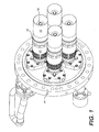
- each combustor includes plural fuel nozzles 20, which are attached to a fuel manifold plate 10 called an endcover.
- the number of fuel nozzles 20 may vary depending on desired performance (e.g., Fig. 3 shows five fuel nozzles and Fig. 1 shows four fuel nozzles).
- Each fuel nozzle 20 has many components including the burner tube 25, which is to the remainder of the fuel nozzle 20 by, for example, a weld 28. Also, each fuel nozzle 20 has a diffusion gas tip 30.
- the fuel nozzles 20 penetrate through a structure called a cap assembly 40, which provides the boundary between compressor air used for the combustion process and a combustion burning zone.
- a burner tube 25 of each fuel nozzle 20 engages the cap assembly 40 through an interface (not shown in Figs. 1-3).
- the interface is located in a tubular cavity 50 between the burner tube 25 and the cap assembly 40.
- the fuel nozzle 20 allows gas and air to premix in the premixer zone 52 of the burner tube 20 prior to the actual combustion in the combustion burning zone or "reaction zone".
- the combustion burning zone is directly downstream from the diffusion gas tip 30 of the burner tube 25. Premixing of gas and air prior to combustion allows a more uniform fuel/air mixture and is important in minimizing emissions in gas turbines.
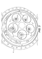
- the cap assembly 40 includes inner body assembly 42, outer body assembly 44 and outer barrel assembly 48.
- the outer barrel assembly 48 is shown with the outer body assembly 44 coupled thereto and the inner body assembly 42 coupled to the outer body assembly 44.
- Four fuel nozzles 20 engage with the cap assembly 40 in the four tubular holes in the outer body assembly 44.
- the locations 46 represent exemplary portions of the cap assembly 40 where a seal can interface with the burner tube of the fuel nozzle. Air can flow through holes 45 (in Fig. 2) and eventually into the tubular cavity 50 between the cap assembly 40 and the burner tube 25 as shown in Fig. 3.
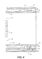
- FIG 4 depicts a partial cross section of the cap assembly 40 with the burner tube 25 engaged therein.
- a seal assembly 60 including the cloth seal is placed in the tubular cavity 50 between the burner tube 25 and the cap assembly 40.
- a seal retainer 55 couples the seal assembly 60 to the cap assembly 40.
- the seal retainer 55 may be permanently fixed to and part of the cap assembly 40.
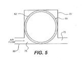
- Figs. 5-7 illustrate exemplary cloth ring seal configurations that may be employed as the interface between burner tube 25 and cap assembly 40 shown in Fig. 4. It should be understood that the cloth seal configurations in Figs. 5-7 may be used as low leakage seals for both static applications, such as around nozzles or tubes, and dynamic applications, such as around rotating components in, but not restricted to, gas or steam turbine environments.
- Figs. 5-7 illustrate a cloth ring seal 65 extending from a first mating body 70 through a tubular cavity 75 between the first mating body 70 and a second mating body 80 and making sealing contact with the second mating body 80.
- the cloth ring seal 65 has an inner circumferential portion which makes sealing contact with the second mating body 80.
- the second mating body is a tubular member such as a nozzle. It should be understood that the second mating body 80 could be a static or rotating component.
- the cloth ring seal 65 has a cloth assemblage 62, which as shown in the illustrative embodiments of Figs. 5 and 6 for example, can be used to define the outer periphery of the cloth ring seal 62.
- an outer periphery of the cloth assemblage 62 can comprise the inner circumferential portion of the cloth ring seal 65 which extends into the tubular cavity 75 and makes sealing contact with the second mating body 80.
- the cloth assemblage 62 can surround a cavity in a central portion of the cloth ring seal 65.
- the cavity can be a tubular void.
- the cloth ring seal 65 can be sandwiched between metal plates (not shown) or otherwise coupled to another portion of the seal assembly.
- the seal assembly is physically attached to the first mating body 70.
- Fig. 6 further includes a shim assemblage 64 such as a sheet metal tube enclosed by a layer of cloth of the cloth assemblage 62.
- the outer periphery of the shim assemblage 64 may oppose the inner periphery of the cloth assemblage 62.
- the inner periphery of the shim assemblage 64 may oppose the periphery of the cavity with the shim assemblage 64 surrounding or enclosing the cavity (e.g., tubular void).
- Each of the cloth assemblage 62 and the shim assemblage 64 may be tubular.
- the cloth ring seal 65 of Fig. 7 while providing sealing functionality equivalent to the cloth ring seal 65 of Fig. 6, illustrates a structural manufacturing alternative to the embodiment of Fig. 6.
- the cloth ring seal 65 of Fig. 7 has a cloth assemblage 62 including planar cloth strips 66A and 66B which may be stitched together and an arcuate cloth portion 66C.
- the arcuate cloth portion 66C has a first end coupled (e.g., stitched) to a planar cloth strip 66B and a second end coupled (e.g., stitched) to a planar cloth strip 66A.
- the arcuate cloth portion 66C and the planar cloth strips 66A, 66B form a closed loop.
- the cloth ring seal 65 of Fig. 7 further includes a shim assemblage 64 with an outer peripheral portion opposing an inner peripheral portion of the cloth assemblage 62.
- the shim assemblage 64 includes two planar shim strips 68A, 68B welded together and an arcuate shim portion 68C.
- the arcuate shim portion 68C has a first end coupled (e.g., welded) to a planar shim strip 68B and a second end coupled (e.g., welded) to a planar shim strip 68A.
- the arcuate shim portion 68C and the planar shims strips 68A, 68B form a closed loop.
- a joining member 72 as shown in Fig. 7 can couple the arcuate cloth portion 66C to planar cloth strip 66A. Also, the joining member 72 can couple the arcuate shim portion 68C to planar shim strip 68A. In the embodiment of Fig. 7, the joining member 72 couples the cloth assemblage 62 to the shim assemblage 64 and in particular couples together arcuate cloth shim portion 68C, arcuate cloth portion 66C, planar shim strip 68A and planar cloth strip 66A.
- the joining member 72 may be a slotted tab or other fastening device.
- planar cloth strips While two planar cloth strips are shown in Fig. 7, multiple planar cloth strips may be connected together by being stitched together as necessary for ease of manufacturing.
- the cloth assemblage in the embodiment of Fig. 5 and the cloth-shim assemblages in the embodiments of Figs. 6 and 7 are designed to permit leakage of fluids (e.g., gas such as air) through the seal.
- fluids e.g., gas such as air
- leakage according to embodiments will be described below in terms of gas leakage, and that such description is merely illustrative and that the embodiments may be applied to leakage of fluids other than gas.
- leakage occurs at least through the cloth assemblage 62 portion of the cloth seal 65 between the inner circumferential portion of the shim assemblage 64 located closest to the mating body 80 and the inner circumferential portion of the cloth seal 65 contacting the second mating body 80.
- the cloth assemblage 62 is porous, and can provide some controlled leakage to provide airflow such as cooling air to downstream locations.
- the arrows show the airflow direction.
- airflow is from the left region of the cavity 75 through the cloth ring seal 65 to the right region of the cavity 75.
- the cloth seal 65 does not include a shim assemblage.
- the cloth seal 65 of Fig. 5 may be utilized in applications where high flow rates are desired, such as for cooling.
- the cloth assemblage 62 of the cloth seal 65 is flexible and includes at least one layer of cloth.
- the cloth layer may include two overlying layers of cloth.
- Each cloth layer may include metal, ceramic and/or polymer fibers that have been woven, knitted or pressed into a layer of fabric.
- Each cloth layer provides sacrificial wear volume and wear resistance without a significant increase in stiffness to the seal.
- Cloth layers due to their porosity, are more resilient than metal layers.
- cloth seals can more readily adapt to the changing size and shape of mating bodies caused by thermal distortion, vibration and other relative movement, thereby providing an effective seal.
- the cloth assemblage 62 can reduce heat conducted to the shim assemblage 64, thereby lessening structural degradation to the mating bodies 70, 80 caused by friction, for example when metal rubs against metal.
- Choices as to the construction of the cloth layer can be made by one skilled in the art when desiring to tune or calibrate the seal based on the wear resistance, flexibility and sealing requirements associated with the particular seal application.
- Multiple cloth layers can include different materials, different layer construction (e.g., woven, knitted or pressed), and/or have different thicknesses or densities depending on the seal application.
- the cloth layer is preferably woven (e.g., using a Dutch Twill weave).
- An exemplary cloth assemblage used in turbine applications employs a Dutch Twill woven cloth layer, the cloth layer being made of a high-temperature Cobalt-based super-alloy such as L-605 or Haynes-25.
- a high-temperature Cobalt-based super-alloy such as L-605 or Haynes-25.
- Other low stiffness and low friction abradable cloth layers can be used depending on the application.
- Teflon may be used as a cloth layer for low temperature applications.
- the shim assemblage 64 of the cloth seals in Figs. 6 and 7 can be flexible, resilient, generally imperforate, and generally impervious to gas.
- the shim assemblage 64 can provide blockage for through cloth leakage, structural stiffness to withstand pressure loads, and resiliency necessary for recovery following interference/excursion, i.e., displacement from a free state.
- the resilient quality of the shim assemblage 64 maintains the sealing properties of the cloth seal while allowing for different surface shapes, assembly misalignment, vibration and/or thermally-induced relative movement between the first mating body 70 and the second mating body 80.
- the flexible shim assemblage 64 serves as a structural member carrying the pressure loads while providing some resiliency, which allows the cloth seal to recover after interference or excursion.
- the shim assemblage 64 comprises at least one shim (thin metal layer) layer, but may comprise two or more superimposed shim layers for increased strength.
- the shim assemblage preferably contains four or fewer shim layers.
- the shim assemblage 64 may have sliced and/or staggered pieces of sheet metal spot-welded together to add flexibility, while maintaining strength, and/or to help the seal conform to the curvature of surfaces of the mating bodies.
- the choices of materials for the shim assemblage and the thickness of each layer of shim can be made by one skilled in the art to tune or calibrate the seal in accordance with sealing, flexibility and resiliency needs of the particular seal application.
- Each shim layer includes a metal, ceramic and/or polymer sheet.
- the shim assemblage generally has a thickness between 1/100 and 1/5 of an inch and each shim layer includes a high temperature, cobalt based super-alloy, such as Inco-750 or HS-188.
- the first mating body corresponds to the cap assembly 40 including the seal retainer 55 which is fixedly attached thereto
- the second mating body corresponds to the fuel nozzle 20, and more particularly burner tube 25, and the cavity 75 corresponds to the tubular cavity 50.
- the air flows from the internal side of the cap assembly (i.e., high pressure side) to the side opening into the combustion zone (i.e., low pressure side).
- a fuel/air premixture exits a premixer zone 52 between the burner tube 25 and diffusion gas tip 30 and enters the combustion burning zone in a swirling manner. Due to the pressure gradients caused by the swirling mixture, some of the hot gases tend to back flow into the tubular cavity 50. The backflow of hot gases into the tubular cavity 50 can damage the hardware including the burner tube 25 and cap assembly 40. To prevent this problem and to purge the tubular cavity of hot gases, a cloth seal according to exemplary embodiments of the present invention shown in Figs. 5-7 can be used as an interface between the burner tube 25 and cap assembly 40.
- the exemplary cloth ring seals according to the invention allow air in the tubular cavity 50 to flow through the seal from the high pressure side to the low pressure side (e.g., from left to right in the cross-sectional view shown in Figs. 5-7) forcing the hot gas backflow out of the tubular cavity 50.
- illustrative low leakage cloth seals according to the invention can be designed to control the leakage passing through the seal by selecting the cloth seal density (e.g., effective flow area through the cloth seal assemblage 62 in Figs. 5-7 when the shim assemblage 64 is impervious) taking into account the pressure drop through the seal interface. That is, knowing the flow conditions (i.e., pressure and temperature) and the pressure drop between the high pressure region and low pressure region, the seal density (effective flow rate through the seal) can be set to a desired leakage flow rate.
- the cloth seal density e.g., effective flow area through the cloth seal assemblage 62 in Figs. 5-7 when the shim assemblage 64 is impervious
- W A eff • 2 ⁇ g c / RT H • P H • P H - P L
- a eff effective area of seal
- g c gravitational constant
- R gas constant for air
- P H upstream pressure - high pressure region pressure
- P L downstream pressure - low pressure region pressure
- T H high pressure region temperature
- W leakage.
- the present invention can apply to many other gas and steam turbine applications as well as other sealing applications.
- embodiments of the cloth seal of the present invention include any application, whether between flat surfaces, around static or rotating tubular members or otherwise, in which flow rate control can be applied.
- the cloth seal according to the invention may be a fully circular ring or it may be in tubular segments as called for in the particular application.
- the cloth ring seal may be placed in a circumferential geometric opening(s) between mating bodies.
- a cloth seal according to illustrative embodiments of the invention can be used in the form of linear strips in applications where relative motion exists between two flat surfaces.
- a cloth ring seal may be used in series with other seals, such as cloth ring seals, brush seal and labyrinth seals, to seal two mating bodies.
Description
- The present invention is directed to seals for dynamic or rotating applications. More particularly, the present invention relates to a cloth ring seal for dynamic and rotating applications.
- Seals can be used to minimize leakage of fluids including gas in applications where two relative movable mechanical members are in close proximity. The members may have substantial relative motion between one another, such as a turbine shaft against lubricating oil reservoir, or a rotatable turbine stage relative to a fixed support structure having to withstand a pressure differential across the stage. Also, the movement between members may be caused by vibration or thermal growth.
- Leakage of gas and air can negatively impact performance of components in many systems including a gas turbine combustion system. Mating components may be formed of different materials and can be subjected to different temperatures during operation. Consequently, the components commonly experience varying degrees of thermal growth. For example, a fuel nozzle burner tube and a combustion liner cap assembly support structure in a gas turbine move radially, axially, and circumferentially relative to one another based on thermal growth. Similar relative movement may also occur due to dynamic pulsing of the combustion process. To prevent leakage and compensate for the relative movement of the fuel nozzle burner tube, a split ring metal seal has been placed around the outer diameter of the fuel nozzle burner tube providing an interface between the burner tube and a portion the cap assembly support structure.
- Rather than an airtight seal, a certain amount of leakage between the fuel nozzle burner tube and the cap assembly support structure is desired. In this regard, hot gases from the combustion reaction zone tend to "backflow" into a tubular cavity between the fuel nozzle burner tube and the cap assembly support structure components. When the hot gases flow into the tubular cavity, they can damage the hardware, which significantly shortens the usable life of the components. To prevent backflow, a certain amount of air leakage needs to be permitted to flow through the seal. In an attempt to address this concern, the conventional split ring metal seal has slots cut through the seal to allow some leakage of air.
- Several problems exist with the split ring metal seal. Since the seal is metal and the interfacing components are metal, the components and seal tend to rub, vibrate or otherwise move against one another causing excessive wear of the seal and the components. Further, the burner tube and cap assembly support structure components and the seal generally do not perfectly fit together due to slight physical discrepancies resulting from manufacture. Stated differently, each component is manufactured to a particular tolerance, and is not perfectly shaped due to real world limitations. In addition, over time the components and seal will tend to change shape due to thermal distortion and physical wear. As a result, the amount of leakage of air around the burner tube cannot be effectively controlled and tends to be non-uniform, varying from one location to another.
- In the past, a substantial number of seals have been employed in turbine systems. Labyrinth seals have been employed between rotating mating surfaces or vibrating mating surfaces. However, labyrinth seals do not easily conform to vibratory movement or rotating surfaces, particularly when the surfaces have imperfections. Consequently, labyrinth seals have not proven particularly effective.
- Brush seals have been used in many environments including in gas and steam turbines. Brush seals generally conform better to rotating and/or vibrating mating surfaces than labyrinth seals including surfaces having imperfections. While brush seals have proven more effective than labyrinth seals, they are exceedingly expensive to manufacture and difficult to handle. For example, the very fine bristle wires of a brush seal are not bound together prior to assembly. As a result, it is an arduous process to lay out a predetermined layer of bristles to the required thickness to form a bristle pack suitable to form the resulting seal. Consequently, there is a need to provide a less expensive mechanism for providing a low leakage seal which is sufficiently resilient to accommodate the dimensional changes in the radial, axial, and circumferential directions resulting from wear and thermal growth. Also, there is a need for a seal that can regulate the amount of leakage there through.
- EP-A-0 762 020 discloses a dynamic seal assembly having a flexible core surrounded by a braided material.
- According to the present invention there is provided a seal assembly comprising a cloth ring seal adapted to seal a tubular cavity between a first mating body and a second mating body, said cloth ring seal having an inner circumferential portion adapted to make- sealing contact with the second mating body;
wherein said cloth ring seal includes a cloth assemblage, the inner circumferential portion of said cloth ring seal adapted to make sealing contact with the second mating body including an outer peripheral portion of said cloth assemblage; and
wherein said cloth ring seal further includes a shim assemblage with an outer peripheral portion opposing an inner peripheral portion of said cloth assemblage, said shim assemblage including a plurality of planar shim strips welded together and an arcuate shim portion, said arcuate shim portion having a first end welded to a first planar shim strip and a second end coupled to a second planar shim strip, wherein said arcuate shim portion and said planar shims strips form a closed loop. - The present invention overcomes many of the shortcomings of prior art seals. According to an illustrative implementation of the present invention, a cloth ring seal interfaces two mating bodies in order to provide a low leakage cloth seal.
- In one aspect of the invention, a low leakage cloth ring seal is provided where, based on the conditions through the interface, the cloth seal may be designed to include an area where fluids including gas can flow through at least portion of the cloth assemblage of the cloth ring seal. Knowing the flow conditions and the pressure differential through the interface, the density of the cloth ring seal including thickness and number of cloth layers may be designed to allow for a desired leakage amount or flow rate. In another aspect of the invention, gas flowing through the seal can be used to purge a cavity of unwanted gases and/or cool the cavity or surfaces of the mating bodies providing the cavity boundaries.
- According to an aspect of the invention, a cloth ring seal is adapted to seal a tubular cavity between a first mating body and a second mating body, where the cloth ring seal has an inner circumferential portion for making sealing contact with the second mating body. In another aspect of the invention, the cloth ring seal includes a tubular cloth assemblage forming the periphery of the cloth ring seal, where a portion of the periphery of the cloth assemblage makes sealing contact with the second mating body. In still another aspect of the invention, a cloth ring seal may further include a shim assemblage surrounded by the cloth assemblage. The cloth assemblage and the shim assemblage may be tubular.
- In another aspect of the invention, a high temperature, woven cloth ring seal can be provided in a tubular cavity between a burner tube of a fuel nozzle and a cap assembly to act as an interface. In another aspect of the invention, leakage through the woven cloth seal can be controlled to purge a tubular cavity separating the burner tube and cap assembly of unwanted hot gases.
- These and other novel advantages, details, embodiments, features and aspects of the present invention will be apparent to those skilled in the art from following the detailed description of the invention, with reference to the accompanying drawings, in which:
- Fig. 1 shows a perspective view of an illustrative fuel nozzle and manifold assembly in a gas turbine.
- Fig. 2 shows an exploded view of an illustrative cap assembly to which plural fuel nozzles can be interfaced in a gas turbine.
- Fig. 3 shows a perspective view taken from a combustion zone of an illustrative cap assembly interfacing with a plurality of fuel nozzles in a gas turbine according to an exemplary embodiment of the present invention.
- Fig. 4 shows a partial cross section of the interface region between the cap assembly and fuel nozzle according to an exemplary embodiment of the present invention.
- Fig. 5 shows a cross-sectional view of an illustrative cloth seal configuration.
- Fig. 6 shows a cross-sectional view of an other illustrative cloth seal configuration.
- Fig. 7 shows a cross-sectional view of an illustrative cloth seal configuration according to an exemplary embodiment of the present invention.
- Referring to Figs. 1-4, an exemplary gas turbine environment in which the present invention may be implemented is shown. In gas turbines, plural combustors are disposed in an annular array around the axis of the machine. As shown in Fig. 1, each combustor includes
plural fuel nozzles 20, which are attached to afuel manifold plate 10 called an endcover. The number offuel nozzles 20 may vary depending on desired performance (e.g., Fig. 3 shows five fuel nozzles and Fig. 1 shows four fuel nozzles). Eachfuel nozzle 20 has many components including theburner tube 25, which is to the remainder of thefuel nozzle 20 by, for example, aweld 28. Also, eachfuel nozzle 20 has adiffusion gas tip 30. Thefuel nozzles 20 penetrate through a structure called acap assembly 40, which provides the boundary between compressor air used for the combustion process and a combustion burning zone. Aburner tube 25 of eachfuel nozzle 20 engages thecap assembly 40 through an interface (not shown in Figs. 1-3). The interface is located in atubular cavity 50 between theburner tube 25 and thecap assembly 40. Thefuel nozzle 20 allows gas and air to premix in thepremixer zone 52 of theburner tube 20 prior to the actual combustion in the combustion burning zone or "reaction zone". The combustion burning zone is directly downstream from thediffusion gas tip 30 of theburner tube 25. Premixing of gas and air prior to combustion allows a more uniform fuel/air mixture and is important in minimizing emissions in gas turbines. - Referring to the exploded view of the
cap assembly 40 depicted in Fig. 2, thecap assembly 40 includesinner body assembly 42,outer body assembly 44 andouter barrel assembly 48. Theouter barrel assembly 48 is shown with theouter body assembly 44 coupled thereto and theinner body assembly 42 coupled to theouter body assembly 44. Fourfuel nozzles 20 engage with thecap assembly 40 in the four tubular holes in theouter body assembly 44. In an illustrative embodiment of the present invention, thelocations 46 represent exemplary portions of thecap assembly 40 where a seal can interface with the burner tube of the fuel nozzle. Air can flow through holes 45 (in Fig. 2) and eventually into thetubular cavity 50 between thecap assembly 40 and theburner tube 25 as shown in Fig. 3. Fig. 4 depicts a partial cross section of thecap assembly 40 with theburner tube 25 engaged therein. As shown, aseal assembly 60 including the cloth seal is placed in thetubular cavity 50 between theburner tube 25 and thecap assembly 40. Aseal retainer 55 couples theseal assembly 60 to thecap assembly 40. Theseal retainer 55 may be permanently fixed to and part of thecap assembly 40. - Figs. 5-7 illustrate exemplary cloth ring seal configurations that may be employed as the interface between
burner tube 25 andcap assembly 40 shown in Fig. 4. It should be understood that the cloth seal configurations in Figs. 5-7 may be used as low leakage seals for both static applications, such as around nozzles or tubes, and dynamic applications, such as around rotating components in, but not restricted to, gas or steam turbine environments. - The embodiments of Figs. 5-7 illustrate a
cloth ring seal 65 extending from afirst mating body 70 through atubular cavity 75 between thefirst mating body 70 and asecond mating body 80 and making sealing contact with thesecond mating body 80. Thecloth ring seal 65 has an inner circumferential portion which makes sealing contact with thesecond mating body 80. In a preferred implementation of each embodiment, the second mating body is a tubular member such as a nozzle. It should be understood that thesecond mating body 80 could be a static or rotating component. Thecloth ring seal 65 has acloth assemblage 62, which as shown in the illustrative embodiments of Figs. 5 and 6 for example, can be used to define the outer periphery of thecloth ring seal 62. As shown in Figs. 5-7, an outer periphery of thecloth assemblage 62 can comprise the inner circumferential portion of thecloth ring seal 65 which extends into thetubular cavity 75 and makes sealing contact with thesecond mating body 80. Thecloth assemblage 62 can surround a cavity in a central portion of thecloth ring seal 65. The cavity can be a tubular void. - The
cloth ring seal 65 can be sandwiched between metal plates (not shown) or otherwise coupled to another portion of the seal assembly. The seal assembly is physically attached to thefirst mating body 70. - In contrast to the exemplary embodiment of Fig. 5, Fig. 6 further includes a
shim assemblage 64 such as a sheet metal tube enclosed by a layer of cloth of thecloth assemblage 62. The outer periphery of theshim assemblage 64 may oppose the inner periphery of thecloth assemblage 62. The inner periphery of theshim assemblage 64 may oppose the periphery of the cavity with theshim assemblage 64 surrounding or enclosing the cavity (e.g., tubular void). Each of thecloth assemblage 62 and theshim assemblage 64 may be tubular. - The
cloth ring seal 65 of Fig. 7, while providing sealing functionality equivalent to thecloth ring seal 65 of Fig. 6, illustrates a structural manufacturing alternative to the embodiment of Fig. 6. Thecloth ring seal 65 of Fig. 7 has acloth assemblage 62 including planar cloth strips 66A and 66B which may be stitched together and anarcuate cloth portion 66C. Thearcuate cloth portion 66C has a first end coupled (e.g., stitched) to aplanar cloth strip 66B and a second end coupled (e.g., stitched) to aplanar cloth strip 66A. Thearcuate cloth portion 66C and the planar cloth strips 66A, 66B form a closed loop. - Also, the
cloth ring seal 65 of Fig. 7 further includes ashim assemblage 64 with an outer peripheral portion opposing an inner peripheral portion of thecloth assemblage 62. Theshim assemblage 64 includes two planar shim strips 68A, 68B welded together and anarcuate shim portion 68C. Thearcuate shim portion 68C has a first end coupled (e.g., welded) to aplanar shim strip 68B and a second end coupled (e.g., welded) to aplanar shim strip 68A. Thearcuate shim portion 68C and the planar shims strips 68A, 68B form a closed loop. - A joining
member 72 as shown in Fig. 7 can couple thearcuate cloth portion 66C toplanar cloth strip 66A. Also, the joiningmember 72 can couple thearcuate shim portion 68C toplanar shim strip 68A. In the embodiment of Fig. 7, the joiningmember 72 couples thecloth assemblage 62 to theshim assemblage 64 and in particular couples together arcuatecloth shim portion 68C,arcuate cloth portion 66C,planar shim strip 68A andplanar cloth strip 66A. The joiningmember 72 may be a slotted tab or other fastening device. - While two planar cloth strips are shown in Fig. 7, multiple planar cloth strips may be connected together by being stitched together as necessary for ease of manufacturing.
- The cloth assemblage in the embodiment of Fig. 5 and the cloth-shim assemblages in the embodiments of Figs. 6 and 7 are designed to permit leakage of fluids (e.g., gas such as air) through the seal. It should be understood that leakage according to embodiments will be described below in terms of gas leakage, and that such description is merely illustrative and that the embodiments may be applied to leakage of fluids other than gas.
- In the embodiments depicted in Figs. 5-7, leakage occurs at least through the
cloth assemblage 62 portion of thecloth seal 65 between the inner circumferential portion of theshim assemblage 64 located closest to themating body 80 and the inner circumferential portion of thecloth seal 65 contacting thesecond mating body 80. Thecloth assemblage 62 is porous, and can provide some controlled leakage to provide airflow such as cooling air to downstream locations. In Figs. 5-7, the arrows show the airflow direction. For the cross-sections shown Figs. 5-7, airflow is from the left region of thecavity 75 through thecloth ring seal 65 to the right region of thecavity 75. In Fig. 5, thecloth seal 65 does not include a shim assemblage. Thecloth seal 65 of Fig. 5 may be utilized in applications where high flow rates are desired, such as for cooling. - According to embodiments, the
cloth assemblage 62 of thecloth seal 65 is flexible and includes at least one layer of cloth. Alternatively, the cloth layer may include two overlying layers of cloth. Each cloth layer may include metal, ceramic and/or polymer fibers that have been woven, knitted or pressed into a layer of fabric. Each cloth layer provides sacrificial wear volume and wear resistance without a significant increase in stiffness to the seal. Cloth layers, due to their porosity, are more resilient than metal layers. Thus, cloth seals can more readily adapt to the changing size and shape of mating bodies caused by thermal distortion, vibration and other relative movement, thereby providing an effective seal. In embodiments such as Figs. 6 and 7, thecloth assemblage 62 can reduce heat conducted to theshim assemblage 64, thereby lessening structural degradation to themating bodies - Choices as to the construction of the cloth layer (e.g., woven, knitted or pressed), the material(s) selected for the cloth layer, and the thickness of the cloth layer can be made by one skilled in the art when desiring to tune or calibrate the seal based on the wear resistance, flexibility and sealing requirements associated with the particular seal application. Multiple cloth layers can include different materials, different layer construction (e.g., woven, knitted or pressed), and/or have different thicknesses or densities depending on the seal application. In turbine applications, the cloth layer is preferably woven (e.g., using a Dutch Twill weave). An exemplary cloth assemblage used in turbine applications employs a Dutch Twill woven cloth layer, the cloth layer being made of a high-temperature Cobalt-based super-alloy such as L-605 or Haynes-25. Other low stiffness and low friction abradable cloth layers can be used depending on the application. For example, Teflon may be used as a cloth layer for low temperature applications.
- The
shim assemblage 64 of the cloth seals in Figs. 6 and 7 can be flexible, resilient, generally imperforate, and generally impervious to gas. Theshim assemblage 64 can provide blockage for through cloth leakage, structural stiffness to withstand pressure loads, and resiliency necessary for recovery following interference/excursion, i.e., displacement from a free state. The resilient quality of theshim assemblage 64 maintains the sealing properties of the cloth seal while allowing for different surface shapes, assembly misalignment, vibration and/or thermally-induced relative movement between thefirst mating body 70 and thesecond mating body 80. Thus, theflexible shim assemblage 64 serves as a structural member carrying the pressure loads while providing some resiliency, which allows the cloth seal to recover after interference or excursion. - The
shim assemblage 64 comprises at least one shim (thin metal layer) layer, but may comprise two or more superimposed shim layers for increased strength. For turbine applications, the shim assemblage preferably contains four or fewer shim layers. Theshim assemblage 64 may have sliced and/or staggered pieces of sheet metal spot-welded together to add flexibility, while maintaining strength, and/or to help the seal conform to the curvature of surfaces of the mating bodies. The choices of materials for the shim assemblage and the thickness of each layer of shim can be made by one skilled in the art to tune or calibrate the seal in accordance with sealing, flexibility and resiliency needs of the particular seal application. Each shim layer includes a metal, ceramic and/or polymer sheet. For turbine applications, the shim assemblage generally has a thickness between 1/100 and 1/5 of an inch and each shim layer includes a high temperature, cobalt based super-alloy, such as Inco-750 or HS-188. - Applying the cloth seal to the gas turbine application shown in Figs. 1-4, the first mating body corresponds to the
cap assembly 40 including theseal retainer 55 which is fixedly attached thereto, the second mating body corresponds to thefuel nozzle 20, and more particularlyburner tube 25, and thecavity 75 corresponds to thetubular cavity 50. In this application, the air flows from the internal side of the cap assembly (i.e., high pressure side) to the side opening into the combustion zone (i.e., low pressure side). - Referring to Figs. 3 and 4, a fuel/air premixture exits a
premixer zone 52 between theburner tube 25 anddiffusion gas tip 30 and enters the combustion burning zone in a swirling manner. Due to the pressure gradients caused by the swirling mixture, some of the hot gases tend to back flow into thetubular cavity 50. The backflow of hot gases into thetubular cavity 50 can damage the hardware including theburner tube 25 andcap assembly 40. To prevent this problem and to purge the tubular cavity of hot gases, a cloth seal according to exemplary embodiments of the present invention shown in Figs. 5-7 can be used as an interface between theburner tube 25 andcap assembly 40. The exemplary cloth ring seals according to the invention, allow air in thetubular cavity 50 to flow through the seal from the high pressure side to the low pressure side (e.g., from left to right in the cross-sectional view shown in Figs. 5-7) forcing the hot gas backflow out of thetubular cavity 50. - The resiliency of cloth seals allows for the accommodation of any nonuniformity in the seal interface (e.g., warping, thermal distortion) in the design of the cloth seal. Also, illustrative low leakage cloth seals according to the invention can be designed to control the leakage passing through the seal by selecting the cloth seal density (e.g., effective flow area through the
cloth seal assemblage 62 in Figs. 5-7 when theshim assemblage 64 is impervious) taking into account the pressure drop through the seal interface. That is, knowing the flow conditions (i.e., pressure and temperature) and the pressure drop between the high pressure region and low pressure region, the seal density (effective flow rate through the seal) can be set to a desired leakage flow rate. In setting the desired leakage, the following relationship can be employed for incompressible flow:
where Aeff = effective area of seal; gc = gravitational constant; R = gas constant for air; PH = upstream pressure - high pressure region pressure; PL = downstream pressure - low pressure region pressure; TH = high pressure region temperature and W = leakage. Embodiments of the present invention regulate fluid flow and provide uniform distribution of leakage around the cloth ring seal. By providing uniform distribution of leakage, "lean" regions and "rich" regions of leakage can be avoided, thereby increasing efficiency. - While the above example of the present invention involves a sealing interface between a cap assembly and burner tube portion of fuel nozzle in a gas turbine system, it should be understood that the present invention can apply to many other gas and steam turbine applications as well as other sealing applications. For example, embodiments of the cloth seal of the present invention include any application, whether between flat surfaces, around static or rotating tubular members or otherwise, in which flow rate control can be applied. In this regard, the cloth seal according to the invention may be a fully circular ring or it may be in tubular segments as called for in the particular application. In certain sealing applications, the cloth ring seal may be placed in a circumferential geometric opening(s) between mating bodies. A cloth seal according to illustrative embodiments of the invention can be used in the form of linear strips in applications where relative motion exists between two flat surfaces. Also, according to embodiments of the invention, a cloth ring seal may be used in series with other seals, such as cloth ring seals, brush seal and labyrinth seals, to seal two mating bodies.
Claims (8)
- A seal assembly comprising a cloth ring seal (65) adapted to seal a tubular cavity (75) between a first mating body (70) and a second mating body (80), said cloth ring seal (65) having an inner circumferential portion adapted to make sealing contact with the second mating body (80): wherein said cloth ring seal (65) includes a cloth assemblage (62), the inner circumferential portion of said cloth ring seal (65) adapted to make sealing contact with the second mating body (80) including an outer peripheral portion of said cloth assemblage (62); and, characterized in that said cloth ring seal (65) further includes a shim assemblage (64) with an outer peripheral portion opposing an inner peripheral portion of said cloth assemblage (62), said shim assemblage (64) including a plurality of planar shim strips (68A, 68B) welded together and an arcuate shim portion (68C), said arcuate shim portion (68C) having a first end welded to a first planar shim strip (68B) and a second end coupled to a second planar shim strip (68A), wherein said arcuate shim portion (68C) and said planar shims strips (68A, 68B) form a closed loop.
- The seal assembly according to claim 1, wherein an inner circumferential portion of said cloth ring seal (65) is adapted to make sealing contact with the second mating body (80).
- The seal assembly according to claim 2, wherein said cloth assemblage (62) is adapted to allow a predetermined flow rate of fluid through the cloth ring seal (65) from a first region of said tubular cavity (75) to a second region of said tubular cavity (75).
- The seal assembly according to claim 3, wherein the thickness of said cloth assemblage (62) is selected to control the flow rate of fluid through said cloth ring seal (65).
- The seal assembly according to claim 1, wherein said cloth ring seal (65) includes a tubular void disposed therein, said tubular void being surrounded by said cloth assemblage (62).
- The seal assembly according to claim 5, the shim assemblage (64) surrounding said tubular void and being surrounded by said cloth assemblage (62).
- The seal assembly according to claim 1, wherein said first mating body (70) is a cap assembly (40) and said second mating body (80) is a fuel nozzle (20).
- The seal assembly according to claim 1, where said tubular member is rotatable.
Applications Claiming Priority (2)
| Application Number | Priority Date | Filing Date | Title |
|---|---|---|---|
| US09/747,014 US6547256B2 (en) | 2000-12-26 | 2000-12-26 | Cloth ring seal |
| US747014 | 2000-12-26 |
Publications (3)
| Publication Number | Publication Date |
|---|---|
| EP1227272A2 EP1227272A2 (en) | 2002-07-31 |
| EP1227272A3 EP1227272A3 (en) | 2003-11-12 |
| EP1227272B1 true EP1227272B1 (en) | 2007-06-06 |
Family
ID=25003315
Family Applications (1)
| Application Number | Title | Priority Date | Filing Date |
|---|---|---|---|
| EP01310530A Expired - Lifetime EP1227272B1 (en) | 2000-12-26 | 2001-12-17 | Cloth ring seal |
Country Status (5)
| Country | Link |
|---|---|
| US (1) | US6547256B2 (en) |
| EP (1) | EP1227272B1 (en) |
| JP (1) | JP4202018B2 (en) |
| KR (1) | KR100779293B1 (en) |
| DE (1) | DE60128783T2 (en) |
Families Citing this family (12)
| Publication number | Priority date | Publication date | Assignee | Title |
|---|---|---|---|---|
| US7565729B2 (en) * | 2006-03-17 | 2009-07-28 | General Electric Company | Methods of manufacturing a segmented brush seal for sealing between stationary and rotary components |
| US7827797B2 (en) * | 2006-09-05 | 2010-11-09 | General Electric Company | Injection assembly for a combustor |
| US20090324393A1 (en) * | 2007-01-25 | 2009-12-31 | Siemens Power Generation, Inc. | Ceramic matrix composite turbine engine component |
| US8087228B2 (en) * | 2008-09-11 | 2012-01-03 | General Electric Company | Segmented combustor cap |
| US8528336B2 (en) * | 2009-03-30 | 2013-09-10 | General Electric Company | Fuel nozzle spring support for shifting a natural frequency |
| US8413447B2 (en) * | 2009-09-16 | 2013-04-09 | General Electric Company | Fuel nozzle cup seal |
| US8613451B2 (en) * | 2010-11-29 | 2013-12-24 | General Electric Company | Cloth seal for turbo-machinery |
| US9108266B2 (en) * | 2011-04-19 | 2015-08-18 | General Electric Company | Welded component, a welded gas turbine component, and a process of welding a component |
| US9349621B2 (en) * | 2011-05-23 | 2016-05-24 | Lam Research Corporation | Vacuum seal arrangement useful in plasma processing chamber |
| US11053614B2 (en) | 2015-06-16 | 2021-07-06 | The Boeing Company | Single-layer ceramic-based knit fabric for high temperature bulb seals |
| US10337130B2 (en) | 2016-02-01 | 2019-07-02 | The Boeing Company | Metal alloy knit fabric for high temperature insulating materials |
| US11603799B2 (en) | 2020-12-22 | 2023-03-14 | General Electric Company | Combustor for a gas turbine engine |
Family Cites Families (20)
| Publication number | Priority date | Publication date | Assignee | Title |
|---|---|---|---|---|
| AT348170B (en) * | 1977-03-25 | 1979-02-12 | Voest Ag | ACCESS LINE FOR CONTINUOUS CASTING PLANTS |
| US4214761A (en) * | 1978-07-31 | 1980-07-29 | Utex Industries, Inc. | Packing construction |
| US4209177A (en) * | 1979-01-15 | 1980-06-24 | Chrysler Corporation | Exhaust seal ring |
| US4453723A (en) | 1980-12-02 | 1984-06-12 | General Connectors Corp. | Seal |
| DE3234376C1 (en) * | 1982-09-16 | 1984-03-01 | Goetze Ag, 5093 Burscheid | Sealing ring |
| US5104286A (en) | 1991-02-08 | 1992-04-14 | Westinghouse Electric Corp. | Recirculation seal for a gas turbine exhaust diffuser |
| DE4109637C1 (en) | 1991-03-23 | 1992-05-14 | Metallgesellschaft Ag, 6000 Frankfurt, De | |
| US5265412A (en) | 1992-07-28 | 1993-11-30 | General Electric Company | Self-accommodating brush seal for gas turbine combustor |
| US5400586A (en) | 1992-07-28 | 1995-03-28 | General Electric Co. | Self-accommodating brush seal for gas turbine combustor |
| US5474306A (en) | 1992-11-19 | 1995-12-12 | General Electric Co. | Woven seal and hybrid cloth-brush seals for turbine applications |
| US5441168A (en) * | 1994-03-21 | 1995-08-15 | Carlini; Anthony J. | Protective seal ring for motorcycle fuel filler neck |
| US5657998A (en) | 1994-09-19 | 1997-08-19 | General Electric Company | Gas-path leakage seal for a gas turbine |
| FR2729447A1 (en) * | 1995-01-18 | 1996-07-19 | Commissariat Energie Atomique | ULTRASOUPLE SEAL WITH DOUBLE JAQUETTE |
| US5509669A (en) | 1995-06-19 | 1996-04-23 | General Electric Company | Gas-path leakage seal for a gas turbine |
| US5586773A (en) | 1995-06-19 | 1996-12-24 | General Electric Company | Gas-path leakage seal for a gas turbine made from metallic mesh |
| DE19532795C2 (en) * | 1995-09-05 | 1999-05-20 | Propack Dichtungen & Packungen | Sealing cord |
| US5934687A (en) | 1997-07-07 | 1999-08-10 | General Electric Company | Gas-path leakage seal for a turbine |
| US5915697A (en) | 1997-09-22 | 1999-06-29 | General Electric Company | Flexible cloth seal assembly |
| US6162014A (en) | 1998-09-22 | 2000-12-19 | General Electric Company | Turbine spline seal and turbine assembly containing such spline seal |
| JP2000220752A (en) * | 1999-02-03 | 2000-08-08 | Akashiya Kako Kk | Water-cut-off method using waterproof seal member |
-
2000
- 2000-12-26 US US09/747,014 patent/US6547256B2/en not_active Expired - Lifetime
-
2001
- 2001-12-17 DE DE60128783T patent/DE60128783T2/en not_active Expired - Lifetime
- 2001-12-17 EP EP01310530A patent/EP1227272B1/en not_active Expired - Lifetime
- 2001-12-24 KR KR1020010084379A patent/KR100779293B1/en active IP Right Grant
- 2001-12-25 JP JP2001390758A patent/JP4202018B2/en not_active Expired - Fee Related
Also Published As
| Publication number | Publication date |
|---|---|
| US6547256B2 (en) | 2003-04-15 |
| DE60128783T2 (en) | 2008-01-31 |
| KR20020053008A (en) | 2002-07-04 |
| US20020079655A1 (en) | 2002-06-27 |
| JP2002267022A (en) | 2002-09-18 |
| JP4202018B2 (en) | 2008-12-24 |
| KR100779293B1 (en) | 2007-11-23 |
| DE60128783D1 (en) | 2007-07-19 |
| EP1227272A3 (en) | 2003-11-12 |
| EP1227272A2 (en) | 2002-07-31 |
Similar Documents
| Publication | Publication Date | Title |
|---|---|---|
| EP1219872B1 (en) | Pressure activated cloth seal | |
| EP1227272B1 (en) | Cloth ring seal | |
| EP0903519B1 (en) | Flexible cloth seal assembly | |
| US7090459B2 (en) | Hybrid seal and system and method incorporating the same | |
| US8246299B2 (en) | Rotor seal segment | |
| EP2239436B1 (en) | Reverse flow ceramic matrix composite combustor | |
| US4989886A (en) | Braided filamentary sealing element | |
| EP2157340B1 (en) | Offset stacked sealing system | |
| US5630700A (en) | Floating vane turbine nozzle | |
| EP1391582A2 (en) | Sealing structure for combustor liner | |
| EP2532837A2 (en) | Seal assemly for gas turbine | |
| EP1013887A1 (en) | A brush seal for gas turbine engines | |
| JP5302979B2 (en) | High temperature seal for turbine engine | |
| US20080284107A1 (en) | Ceramic Brush Seals | |
| JP2009115085A (en) | First stage nozzle to transition piece seal | |
| US4022481A (en) | Compliant structural members | |
| US20070187900A1 (en) | Non-metallic brush seals | |
| USRE30600E (en) | Compliant structural members | |
| CN108495975B (en) | Transition system side seal for gas turbine engine | |
| US10724393B2 (en) | Flexible small cavity seal for gas turbine engines | |
| Aksit et al. | Advanced flexible seals for gas turbine shroud applications | |
| WO2018089014A1 (en) | Seal assembly between a transition duct and a stage one turbine vane structure |
Legal Events
| Date | Code | Title | Description |
|---|---|---|---|
| PUAI | Public reference made under article 153(3) epc to a published international application that has entered the european phase |
Free format text: ORIGINAL CODE: 0009012 |
|
| AK | Designated contracting states |
Kind code of ref document: A2 Designated state(s): AT BE CH CY DE DK ES FI FR GB GR IE IT LI LU MC NL PT SE TR |
|
| AX | Request for extension of the european patent |
Free format text: AL;LT;LV;MK;RO;SI |
|
| PUAL | Search report despatched |
Free format text: ORIGINAL CODE: 0009013 |
|
| AK | Designated contracting states |
Kind code of ref document: A3 Designated state(s): AT BE CH CY DE DK ES FI FR GB GR IE IT LI LU MC NL PT SE TR |
|
| AX | Request for extension of the european patent |
Extension state: AL LT LV MK RO SI |
|
| RIC1 | Information provided on ipc code assigned before grant |
Ipc: 7F 01D 11/00 B Ipc: 7F 23R 3/00 B Ipc: 7F 16J 15/32 A Ipc: 7F 16J 15/08 B Ipc: 7F 16J 15/10 B |
|
| 17P | Request for examination filed |
Effective date: 20040512 |
|
| AKX | Designation fees paid |
Designated state(s): CH DE FR GB LI |
|
| 17Q | First examination report despatched |
Effective date: 20041011 |
|
| GRAP | Despatch of communication of intention to grant a patent |
Free format text: ORIGINAL CODE: EPIDOSNIGR1 |
|
| GRAS | Grant fee paid |
Free format text: ORIGINAL CODE: EPIDOSNIGR3 |
|
| GRAA | (expected) grant |
Free format text: ORIGINAL CODE: 0009210 |
|
| AK | Designated contracting states |
Kind code of ref document: B1 Designated state(s): CH DE FR GB LI |
|
| REG | Reference to a national code |
Ref country code: GB Ref legal event code: FG4D |
|
| REG | Reference to a national code |
Ref country code: CH Ref legal event code: EP |
|
| REF | Corresponds to: |
Ref document number: 60128783 Country of ref document: DE Date of ref document: 20070719 Kind code of ref document: P |
|
| REG | Reference to a national code |
Ref country code: CH Ref legal event code: NV Representative=s name: SERVOPATENT GMBH |
|
| ET | Fr: translation filed | ||
| REG | Reference to a national code |
Ref country code: CH Ref legal event code: PFA Owner name: GENERAL ELECTRIC COMPANY Free format text: GENERAL ELECTRIC COMPANY#1 RIVER ROAD#SCHENECTADY, NY 12345 (US) -TRANSFER TO- GENERAL ELECTRIC COMPANY#1 RIVER ROAD#SCHENECTADY, NY 12345 (US) |
|
| PLBE | No opposition filed within time limit |
Free format text: ORIGINAL CODE: 0009261 |
|
| STAA | Information on the status of an ep patent application or granted ep patent |
Free format text: STATUS: NO OPPOSITION FILED WITHIN TIME LIMIT |
|
| 26N | No opposition filed |
Effective date: 20080307 |
|
| REG | Reference to a national code |
Ref country code: FR Ref legal event code: PLFP Year of fee payment: 15 |
|
| REG | Reference to a national code |
Ref country code: FR Ref legal event code: PLFP Year of fee payment: 16 |
|
| REG | Reference to a national code |
Ref country code: FR Ref legal event code: PLFP Year of fee payment: 17 |
|
| PGFP | Annual fee paid to national office [announced via postgrant information from national office to epo] |
Ref country code: DE Payment date: 20181126 Year of fee payment: 18 |
|
| PGFP | Annual fee paid to national office [announced via postgrant information from national office to epo] |
Ref country code: GB Payment date: 20181127 Year of fee payment: 18 Ref country code: FR Payment date: 20181127 Year of fee payment: 18 Ref country code: CH Payment date: 20181126 Year of fee payment: 18 |
|
| REG | Reference to a national code |
Ref country code: CH Ref legal event code: PCAR Free format text: NEW ADDRESS: WANNERSTRASSE 9/1, 8045 ZUERICH (CH) |
|
| REG | Reference to a national code |
Ref country code: DE Ref legal event code: R119 Ref document number: 60128783 Country of ref document: DE |
|
| REG | Reference to a national code |
Ref country code: CH Ref legal event code: PL |
|
| GBPC | Gb: european patent ceased through non-payment of renewal fee |
Effective date: 20191217 |
|
| PG25 | Lapsed in a contracting state [announced via postgrant information from national office to epo] |
Ref country code: FR Free format text: LAPSE BECAUSE OF NON-PAYMENT OF DUE FEES Effective date: 20191231 Ref country code: GB Free format text: LAPSE BECAUSE OF NON-PAYMENT OF DUE FEES Effective date: 20191217 Ref country code: DE Free format text: LAPSE BECAUSE OF NON-PAYMENT OF DUE FEES Effective date: 20200701 |
|
| PG25 | Lapsed in a contracting state [announced via postgrant information from national office to epo] |
Ref country code: CH Free format text: LAPSE BECAUSE OF NON-PAYMENT OF DUE FEES Effective date: 20191231 Ref country code: LI Free format text: LAPSE BECAUSE OF NON-PAYMENT OF DUE FEES Effective date: 20191231 |