EP1226773A1 - Office chair - Google Patents
Office chair Download PDFInfo
- Publication number
- EP1226773A1 EP1226773A1 EP02001138A EP02001138A EP1226773A1 EP 1226773 A1 EP1226773 A1 EP 1226773A1 EP 02001138 A EP02001138 A EP 02001138A EP 02001138 A EP02001138 A EP 02001138A EP 1226773 A1 EP1226773 A1 EP 1226773A1
- Authority
- EP
- European Patent Office
- Prior art keywords
- chair
- tension
- lumbar
- seat
- cam
- Prior art date
- Legal status (The legal status is an assumption and is not a legal conclusion. Google has not performed a legal analysis and makes no representation as to the accuracy of the status listed.)
- Granted
Links
Images


Classifications
-
- A—HUMAN NECESSITIES
- A47—FURNITURE; DOMESTIC ARTICLES OR APPLIANCES; COFFEE MILLS; SPICE MILLS; SUCTION CLEANERS IN GENERAL
- A47C—CHAIRS; SOFAS; BEDS
- A47C7/00—Parts, details, or accessories of chairs or stools
- A47C7/02—Seat parts
- A47C7/28—Seat parts with tensioned springs, e.g. of flat type
- A47C7/282—Seat parts with tensioned springs, e.g. of flat type with mesh-like supports, e.g. elastomeric membranes
-
- A—HUMAN NECESSITIES
- A47—FURNITURE; DOMESTIC ARTICLES OR APPLIANCES; COFFEE MILLS; SPICE MILLS; SUCTION CLEANERS IN GENERAL
- A47C—CHAIRS; SOFAS; BEDS
- A47C1/00—Chairs adapted for special purposes
- A47C1/02—Reclining or easy chairs
- A47C1/022—Reclining or easy chairs having independently-adjustable supporting parts
- A47C1/03—Reclining or easy chairs having independently-adjustable supporting parts the parts being arm-rests
-
- A—HUMAN NECESSITIES
- A47—FURNITURE; DOMESTIC ARTICLES OR APPLIANCES; COFFEE MILLS; SPICE MILLS; SUCTION CLEANERS IN GENERAL
- A47C—CHAIRS; SOFAS; BEDS
- A47C1/00—Chairs adapted for special purposes
- A47C1/02—Reclining or easy chairs
- A47C1/031—Reclining or easy chairs having coupled concurrently adjustable supporting parts
- A47C1/032—Reclining or easy chairs having coupled concurrently adjustable supporting parts the parts being movably-coupled seat and back-rest
- A47C1/03255—Reclining or easy chairs having coupled concurrently adjustable supporting parts the parts being movably-coupled seat and back-rest with a central column, e.g. rocking office chairs
-
- A—HUMAN NECESSITIES
- A47—FURNITURE; DOMESTIC ARTICLES OR APPLIANCES; COFFEE MILLS; SPICE MILLS; SUCTION CLEANERS IN GENERAL
- A47C—CHAIRS; SOFAS; BEDS
- A47C7/00—Parts, details, or accessories of chairs or stools
- A47C7/36—Support for the head or the back
- A47C7/40—Support for the head or the back for the back
- A47C7/46—Support for the head or the back for the back with special, e.g. adjustable, lumbar region support profile; "Ackerblom" profile chairs
- A47C7/462—Support for the head or the back for the back with special, e.g. adjustable, lumbar region support profile; "Ackerblom" profile chairs adjustable by mechanical means
Definitions
- the present invention relates to seating, and more particularly to office and task seating.
- office and task seating is typically provided with a high degree of adjustability.
- the resilient back recline permits the back to tilt or recline rearwardly in a resilient manner under force applied by the occupant.
- the resilient back recline permits the back to recline rearwardly when an occupant leans backward in the chair.
- the back recline mechanism is spring-loaded to provide a desired level of resistance to rearward movement and to return the back to the default or home position when the occupant leans forward.
- U.S. Patent 4,842,333 to Meiller which is incorporated herein by reference.
- the Meiller mechanism operatively links the seat and back portions of the chair so that tilting of the back results in forward and rearward movement of the seat.
- This mechanism significantly reduces the amount of change in the occupant's visual and reach zones when he or she reclines in the chair. It also provides substantially uniform spacing between the seat and back through various degrees of inclination, thereby reducing the tendency of the back to "untuck" the occupant's shirt with each reclining movement.
- load bearing fabric in the seat and back of conventional office seating.
- load bearing fabric constructions the load bearing surfaces of the seat and back are defined by a fabric that is stretched over a corresponding opening.
- the load bearing fabric not only supports the occupant, but also has enough resiliency to provide the desired level of comfort. In typical constructions of this type, no additional cushioning or trim is required in the load bearing regions of the seat and back. Because of the open weave or knit construction of many load bearing fabrics, the seat and back of the load bearing constructions is typically see-through. This means that any lumbar support or other mechanisms secured to the back or seat will be visible during ordinary use of the chair. As a result, there is an ongoing need for a lumbar support that is not only effective in controlling the contour of the lumbar region, but also aesthetically pleasing.
- a line of chairs may include both a task chair and an executive chair; with the task chair designed to meet a lower price point having a relatively small back and sometimes limited adjustability.
- the executive chair may be design for a higher price point, typically having a larger back and being fully adjustable. This requires the separate design and manufacture of different chair backs, thereby reducing the manufacturing efficiencies associate with larger volumes.
- the aforementioned problems are overcome by the present invention wherein a chair is provided with mechanisms that permit a wide range of adjustability of the chair.
- the chair generally includes an adjustable resilient back recliner mechanism, a pair of adjustable armrests, modular upper back portions and an adjustable lumbar support.
- the present invention provides a control mechanism that permits simple adjustment of various elements of the chair.
- the control mechanism includes a tension knob that is rotated to provide control over the tension in the resilient back recline mechanism, a height push-button that controls the height of the seat and a multi-position limit lever that provides control over the limit of the resilient back recline mechanism.
- the tension knob provides a full range of adjustment through only 180 degrees of rotation. of the knob.
- the chair includes a spring that provides tension in the back recliner mechanism.
- the tension knob is operatively connected to the spring by a cam, lever and linkage. Rotation of the tension knob causes the cam to pivot the lever, which in turn varies the pre-tension in the spring through operation of the linkage.
- the tension control mechanism provides a simple and effective control mechanism that is easily moved through its entire range of motion without undue effort.
- the height push button operates a wing that actuates a toggle switch protruding from the top of the upper tube of the support column.
- the height push button is preferably mounted within the tension control knob, where it is readily accessible. As a result, the height control is easily located and operated.
- recline limit control mechanism includes a lever that is preferably mounted to the shaft of the tension control knob where it is readily accessible.
- the lever is operatively connected to a rotor that extends and retracts a cable in response to rotation of the lever.
- the cable is connected to a stop that travels in the path of a trackway on the seat frame to limit movement of the seat frame and consequently the back.
- the recline limit control mechanism is simple and effective, yet provides a high degree of adjustability to the recline limit.
- the recline limit lever is mounted adjacent the tension knob and height control so that the various seat controls are arranged in a single location, where they are easily located and operated by the occupant.
- the present invention provides a lumbar support that includes a lumbar pad and a lumbar cam.
- the lumbar cam includes lobes of differing dimensions arranged along a shaft.
- the shaft is rotatably mounted to the lumbar pad, thereby permit adjustment of the contour of the lumbar region by rotation of the lumbar cam.
- the lumbar pad and lumbar cam are exposed and visible to the occupant.
- the lumbar support is height adjustable. More specifically, the lumbar pad and lumbar cam are movably mounted within a vertical channel.
- the lumbar support provides a high level of vertical and depth adjustment to the lumbar region through simple rotation of the lumbar cam.
- the degree of adjustability can easily be adjusted by variations in the lobes of the lumbar cam.
- the exposed lumbar support is aesthetically pleasing and permits visual inspection of its components.
- the present invention provides an armrest control mechanism that permits adjustment of the height and angle of the armpads.
- the armrest control mechanism for each armrest includes a tube movably mounted in an upright and a ratchet mechanism that permits the height of the tube in the upright to be raised simply by lifting the armpads.
- the ratchet mechanism preferably includes a reset mechanism that permits each tube to be lowered only after it has been raised to its upper extreme.
- the armrest height control mechanism provides a high degree of vertical adjustment and, because there are no actuators, is easily operated simply by lifting or lowering the armpads.
- the armrest control mechanism also preferably includes an armpad pivot mechanism that permits pivotal adjustment of the armpads.
- the pivot mechanism generally includes a lower plug that carries the plunger of the ratchet mechanism and an upper plug that is affixed to the tube and rotatably mounted to the lower plug.
- the pivot mechanism permits the tube, and hence the armpad, to be rotated without rotating the plunger. This mechanism provides a high degree of adjustability and is easily incorporated with the armrest height control mechanism.
- the present invention provides a modular back assembly that permits variation in the overall shape of the back through the installation of interchangeable upper back portion components.
- the back defines a mounting platform that is adapted to receive any of a variety of upper back portions through a snap-fit connection.
- the mounting platform is preferably disposed at the upper extreme of the back such that the overall shape and height of the back is readily varied by differently shaped upper back portion components.
- the modular upper back portion permits inexpensive variation in the overall shape of the back, thereby eliminating the need for the design, development and manufacture of entirely different backs to meet different price points.
- a chair in accordance with a preferred embodiment of the present invention is shown in Figs. 1-2 and 51-55, and generally designated 10.
- the load bearing surfaces of the chair 10 are defined by load bearing fabric rather than conventional cushion and fabric constructions.
- the chair 10 is, however, illustrated with the load bearing fabric removed in all but Fig. 1 to show the structure of the present invention.
- the loading bearing fabric attachment of the preferred embodiment is described in detail in U.S. Patent Application Serial No. 09/769,967, entitled LOAD BEARING FABRIC ATTACHMENT AND ASSOCIATED METHOD, which was filed on January 25, 2001, by Timothy P. Coffield et al, which is incorporated herein by reference.
- the present invention is described in connection with a chair incorporating load bearing fabric, the present invention is well suit for use in other constructions, for example, conventional cushion and fabric construction.
- the chair 10 includes a seat 12, a back 14 and an armrest assembly 16 mounted atop a height-adjustable pedestal 18.
- the seat 12 and back 14 are movably mounted upon a recliner mechanism 20 that permits the back 14 to recline and the seat 12 to shift forwardly and rearwardly in concert with reclining movement of the back 14 (See Figs. 1, 18 and 52).
- a lumbar support 30 is movably mounted to the back 14 in the lumbar region.
- the lumbar support 30 is height-adjustable by movement of the lumbar support in a vertical track and is depth-adjustable by rotation of a lumbar cam. As perhaps best shown in Figs.
- the armrest assembly 16 is mounted atop the pedestal 18 so that it does not move with the seat 12 and back 14.
- the armrest assembly 16 includes a pair of adjustable armrests 22 and 24 disposed on opposite sides of the seat 12.
- the recliner mechanism 20 is mounted atop the pedestal 18 so that adjustment of the height of the pedestal 18 results in adjustment of the seat 12, back 14 and armrest assembly 16.
- the chair 10 includes a control mechanism 26 that permits push-button control of the height of the chair 10, rotational control of the tension of the resilient back recliner mechanism and multi-positional lever control of the limit of the resilient back recliner mechanism.
- the chair 10 further includes a modular upper back portion 90 that can be replaced by alternative modular back portions, such as upper back portion 90' shown in phantom lines in Fig. 2, to vary the overall shape of the back 14.
- the pedestal 18 preferably includes five legs 32 terminating in casters 34 and a support column 36 extending upwardly from the legs 32.
- the support column 36 is a generally conventional height-adjustable support column having telescopic upper 38 and lower 40 tubes.
- a spring or other biasing device is disposed within the lower tube 40 beneath the upper tube 38 to bias the upper tube 38 in an extended position.
- the support column 36 also includes a generally conventional height actuator (not shown) for controlling the height of the column 36 and hence the height of the seat 12.
- the height actuator (not shown) is contained within the support column 36 and includes a toggle switch 37 that protrudes from the upper end of the upper tube 38. Actuation of the toggle switch 37 releases the locking mechanism of the height actuator, thereby permitting adjustment of the height of the support column 36 in a conventional manner.
- the height actuator is operated by the height control mechanism 160, as will be described in more detail below.
- the described pedestal 18 is merely exemplary, and it can be replaced by any of a wide variety of conventional pedestals as desired.
- the seat 12, back 14 and armrest assembly 16 are mounted to the pedestal 18 upon a recliner mechanism 20.
- the recliner mechanism 20 permits the back 14 to recline while linking the seat 12 to the back 14 so that the seat slides forwardly and rearwardly as the back 14 moves.
- the general operation of the recliner mechanism 20 is similar to that of the mechanism disclosed in U.S. Patent 4,842,333 to Meiller, which is incorporated herein by reference.
- the recliner mechanism 20 generally includes a casting 42 that is mounted atop the support column 36 in a conventional manner. The casting 42 movably receives and supports the seat 12 and back 14 of the chair 10, in part by J-bar 50 as described in more detail below. As shown in Figs.
- the casting 42 is a generally horizontally extending plate including a pair of roller bearing tracks 62 disposed on opposite lateral sides.
- the tracks 62 open in opposite directions and are adapted to receive roller bearings mounted to the J-bar 50.
- Each track 62 includes forwardly inclined rear portion 66 and a rearwardly inclined forward portion 68 that cooperatively define a shallow V-shaped channel.
- the rear portions 66 receive and shepherd the rear roller bearings 60 of the J-bar 50.
- the forward portions 68 receive and shepherd the front roller bearings 58 of the J-bar 50.
- the configuration and operation of the J-bar 50 is described in more detail below.
- the casting 42 further includes a pair of front roller bearings 70 that support the front of the seat 12.
- the front roller bearings 70 are mounted to opposite lateral sides at the forward edge of the casting 42 and are preferably mounted upon pins 74.
- the pins 74 are mounted, preferably by press-fitting, within bores 75 (See Fig. 6).
- the casting 42 also includes a centrally located mount 48 that fitted over the upper tube 38 of the support column 36.
- the casting 42 may be secured to the upper tube 38 by a set screw, snap ring, retaining clip or other conventional retaining device (not shown).
- the casting 42 also includes a plurality of mounting components for various control mechanisms. More specifically, the casting 42 includes a height control clevis 272 adjacent to the mount 48 (See Fig.
- the height control clevis 272 generally includes a pair of spaced uprights 318 and 320 that retain wing 264.
- the recline limit track 310 generally includes a pair of spaced walls 322 and 324, at least one of which preferably includes a longitudinally extending notch 314 that entraps a corresponding retaining rib 316 on stop 150. The function of these mounting components is described in more detail below.
- the casting 42 may also include top 44 and bottom 46 shrouds that enclose a portion of the casting 42.
- the casting 42 is preferably cast from aluminum or other conventional materials, but may be machined or otherwise manufactured as desired.
- the J-bar 50 mounts the back 14 and the rear portion of the seat 12 to the casting 42.
- the J-bar 50 includes a pair of L-shaped recliner legs 52 and 54 extending from a U-shaped back support 56.
- a front roller bearing 58 and a rear roller bearing 60 are mounted to the interior of each leg 52 and 54 upon corresponding front 80 and rear 82 pins.
- the roller bearings 58 and 60 are received within the roller bearing tracks 62 of the casting 42. More specifically, the front rollers 58 are received within the front portions 68 and the rear rollers 60 are received within the rear portions 66.
- Each leg 52 and 54 defines a seat mounting slot 78 that is aligned with the corresponding rear pin 82.
- the back support 56 defines a plurality of back mounting holes 84 for securing the back 14 to the back support 56 by screws 85 or other conventional fasteners, as well as a plurality of lumbar mounting holes 83 for securing the lumbar support 30 to the back support 56 by screws 81 or other conventional fasteners.
- the J-bar 50 is preferably cast from aluminum or other conventional materials, but may be machined or otherwise manufactured as desired.
- the pins 80 and 82 are preferably manufactured from steel and are preferably press-fitted into corresponding holes in the J-bar 50.
- the back 14 generally includes a back frame 86, a back carrier 88 and a lumbar support 30.
- the back frame 86 is a peripheral framework receiving and providing structural support for the back carrier 88.
- the back frame 86 defines a channel 72 extending entirely around the peripheral framework.
- the back frame 86 defines a plurality of slots 76 spaced around the base of the channel 72 for use in securing the back carrier 88 to the back frame 86 as described in more detail below (See Fig. 11).
- the back frame 86 also includes a plurality of screw bosses 64 for use in securing the back frame 86 to the J-bar 50 by screws.
- the back frame 86 is preferably injection molded from a material having sufficient structural characteristics to support the back carrier 88 and the associated loads.
- the back frame 86 may be manufactured from thirty percent glass-filled polypropylene or from nylon.
- the back carrier 88 is secured to the back frame 86 within the channel 72 and includes a modular upper back portion 90 that permits adjustment of the shape of the upper portion of the back 14.
- the back carrier 88 is shown in Figs. 12 and 13 with the load bearing fabric removed to provide a clearer understanding of the subject matter of the present invention. Certain aspects of the back carrier 88 are described in detail in U.S. Patent Application Serial No. 09/769,967, which as noted above is incorporated herein by reference. Suffice it to say that the back carrier 88 includes a load bearing fabric 87 (See Fig. 1) that is stretched across and secured to the back carrier 88, preferably as an integral part of the back fabric carrier molding process.
- the phantom line FL shows the approximate position at which the fabric 87 enters the carrier 88.
- the back carrier 88 is fitted into channel 72 and is preferably intersecured with the back frame 86 by snaps 89 that are snap-fitted into slots 76.
- the snaps 89 have hooked ends that securely interlock the snaps 89 and slots 76.
- the back carrier 88 can, however, be secured to the back frame 86 in alternative ways, for example, by screws (not shown). Although the present invention is described in connection with a back frame 86 supporting a load bearing fabric 87, the back frame could alternatively be a conventional cushioned back or other similar construction.
- the back carrier 88 is preferably injection molded from a glass filled polypropylene or other similar materials.
- the back carrier 88 is adapted to receive any of a number of modular upper back portions 90, 90'.
- the back carrier 88 includes a mounting platform 110 that is recessed from the front surface of the carrier 88 and includes a plurality of screw bosses 94 for screwing the upper back portion 90 to the back carrier 88.
- a pair of upper back portions 90 and 90' are shown in Figs.14-17.
- Upper back portion 90 (Figs. 14 and 15) is intended primarily for use on task seating, while upper back portion 90' (Figs. 16 and 17) is intended for use with executive seating.
- Each modular upper back portion 90, 90' includes a front surface 113, 113' that is preferably configured to align with the front surface of the back carrier 88 to provide a substantially uniform back 14.
- the two upper back portions 90 and 90' include identical mounting platforms 92 and 92'. Only the mounting platform 92 of upper back portion 90 will be described in detail, it being understood that the mounting platform 92' of upper back portion 90', and other modular upper back portions, is essentially identical to mounting platform 92.
- the mounting platform 92 is shaped to mate with the platform 110 of the back carrier 88, and includes a plurality of screw bosses 112 that align with the screw bosses 94 of the back carrier 88.
- the upper back portion 90 also includes a pair of tabs 114 that extend from opposite ends of the mounting platform 92 and are trapped behind the back carrier 88.
- the tabs 114 prevent the opposite ends of the upper back portion 90 from separating from the back carrier 88 under a rearward load.
- the desired upper back portion is mounted to the back carrier 88 simply by fitting the tabs 114 behind the back frame 88 and installing screws through the screw bosses 94 in the back carrier 88 into the screw bosses 112 in the upper back portion 90.
- the modular upper back portions could be secured to the back carrier 88 by other forms of attachment.
- the upper back portion 90 and back carrier mounting platform 110 may be provided with snap-together fittings (not shown) that supplement or replace the screws.
- the upper back portion can be padded and upholstered as desired.
- the back 14 also includes a lumbar support 30 that permits adjustment of the contour of the back 14 in the lumbar region.
- the lumbar support 30 generally includes a lumbar pad 120 and a lumbar cam 122 that are mounted to the rear of the back frame 86.
- the lumbar pad 120 and lumbar cam 122 are mounted for vertical movement to permit adjustment of the vertical position of the lumbar support 30.
- the lumbar pad 120 generally includes a plastic insert 300 and a urethane overmold 302 that is molded over the insert 300. Although the insert 300 is not illustrated separately, the profile of the insert 300 is shown in broken lines in Fig. 19.
- the insert 300 provides the lumbar pad 120 with the desired level of rigidity and structural integrity.
- the insert 300 extends the entire length of the lumbar pad 120 and generally includes a plurality of discs 304 positioned between a pair of clevises 132.
- the center portion 305 of each disc 304 is exposed through the overmold 302 for engagement with the corresponding lobe 142, 144 and 146 of the lumbar cam 122.
- the clevises 132 are located at opposite ends of the insert 300 to receive opposite ends of the lumbar cam 122.
- the insert 300 also includes a pair of flanges 134 inwardly from each clevis 132.
- the flanges 134 cooperate with corresponding ribs on the lumbar cam 122 to bias the lumbar cam 122 in one of four distinct positions.
- the urethane overmold 302 is substantially resilient providing the lumbar pad 120 with the desired cushioning.
- the lumbar cam 122 is rotatably mounted to the lumbar pad 120, such that it can be rotated to provide the flexible lumbar pad 120 (and consequently the lumbar region of the back 14) with different shapes.
- the lumbar cam 122 generally includes a pair of knobs 138 located on opposite ends of a shaft 140.
- the shaft 140 includes three spaced lobes 142, 144 and 146 that each vary in radius (or height) about the shaft 140.
- the lobes 142, 144 and 146 are shaped to provide the lumbar region of the back 14 with four different contour profiles based on the rotational position of the lumbar cam 122.
- the preferred cross-sectional shapes of the lobes 142, 144 and 146 are shown in Figs. 22B, 22C and 22D. In a first position, all three lobes 142, 144 and 146 are substantially flat, providing a generally flat lumbar region. In a second position, all three lobes 142, 144 and 146 have substantial height, providing substantial support in the lumbar region.
- the three lobes 142, 144 and 146 have substantially more height than in the second position, providing greater support across the lumbar region.
- the outer lobes 142 and 146 have the same height provided in the third position while the center lobe 144 is provided with the same height as in the second position, providing substantial support in the center of the lumbar region and greater support in the outer portions of the lumbar region.
- the lumbar cam 122 is preferably injection molded from a substantially rigid polymeric material, such as acetal.
- the material is selected to provide the lumbar cam 122 will a limited degree of flexibility under conventional loads.
- the knobs 138 are preferably overmolded with a softer rubber or polymeric material, such as kraton, to provide the desired feel.
- the lumbar support 30 may be painted using conventional in-mold coating techniques.
- the lumbar pad 120 and/or lumbar cam 122 can be painted by applying an in-mold paint to the interior surfaces of the mold parts prior to the injection molding process so that the paint is molded directly in place on the component.
- the lumbar pad 120 and lumbar cam 122 are secured to the back frame 86 by brackets 124 and 126.
- the brackets 124 and 126 are preferably secured to the back frame by screws 81 or other conventional fasteners, and each defines a vertically extending channel 128 that receives the lumbar pad 120 and the lumbar cam 122.
- the lumbar pad 120 and the lumbar cam 122 are slidably entrapped within the channels 128.
- Each bracket 124 and 126 also includes a ribbed vertical adjustment flange 130 that extends along the channel 128.
- the ribs 136 arranged along the flange 130 function to bias the lumbar 120 and lumbar cam 122 in one of seven predetermined vertical positions.
- the described brackets are merely exemplary and may be varied from application to application to provide the lumbar with the desired adjustability.
- the location of the brackets, the size of the channel and the number, size and shape of vertical adjustment flanges may vary to alter the adjustability profile of the lumbar support.
- the seat 12 generally includes a seat frame 98 and a seat carrier 100 mounted to the seat frame 98.
- the seat frame 98 is generally concave, including a peripheral portion 96 defining a channel 97 for receiving the seat carrier 100.
- the seat frame 98 includes a pair of downwardly extending mounting posts 102 disposed toward opposite lateral sides of the frame 98.
- the mounting posts 102 are fitted within the seat mounting slots 78 and are pivotally secured to the rear pins 82 by mounting caps 95 (See Figs. 3 and 52).
- the front of the frame 86 is movably mounted to the casting 42 by a track and roller assembly. More specifically, the seat 12 includes roller tracks 104 disposed on opposite lateral sides of the seat frame 98. The tracks 104 entrap and are operatively interfitted with the front roller bearings 70 of the casting 42. As a result, the seat frame 98 (and hence the seat 12) is capable of forward and rearward movement with respect to the casting 42.
- the tracks 104 are preferably pre-manufactured and secured to the seat frame 98 by interaction of ribs 107 and locking tabs 99, which are integrally formed with the seat frame 98.
- the tabs 99 are preferably snap-fitted into corresponding slots 109 in the tracks 104.
- the tracks 104 may be secured by screws, bolts or other conventional fasteners.
- the seat frame 98 also includes a trackway 106 that interacts with the recline limit control mechanism 28 to adjustably limit the rearward recline of the back 14.
- the trackway 106 includes a plurality of offset steps 108a-e extending downwardly from the undersurface of the seat frame 98.
- this mechanism permits the user to set the maximum rearward recline of the back 14 to one of a plurality of different settings.
- the recline limit control mechanism 28 provides five degrees of adjustment, one defined by each of the offset steps 108a-e. Operation of the recline limit control mechanism 28 is described in more detail below.
- the trackway 106 is preferably molded directly into the seat frame 98, but may be separately manufactured and secure to the seat frame 98, if desired.
- the seat frame 98 also includes a crankshaft mount 162 for mounting the crankshaft 162 of the tension linkage.
- the crankshaft mount 162 includes three separate portions 162a, 162b and 162c that receive the opposite ends and center portion of the crankshaft 164.
- the crankshaft 164 is snap-fitted into center portion 162b. Opposite ends of the crankshaft 164 are rotatably received in end portions 162a and 162c.
- the seat frame 98 further includes a Z-bar mount 380 for mounting the Z-bar 352 of the tension linkage.
- the Z-bar mount 380 includes three separate portions 380a, 380b and 380c. Portions 380a and 380c rotatably receive end portions of the Z-bar 352.
- the Z-bar 352 is snap-fitted into center portion 380b. Operation of the crankshaft 164, Z-bar 352 and the tension control linkage is described in more detail below.
- the seat frame 98 is preferably injection molded from a material having sufficient structural characteristics to support the seat carrier 100 and the associated loads.
- the seat frame 98 may be manufactured from thirty percent glass-filled polypropylene or from nylon.
- the seat carrier 100 is secured to the seat frame 98 within the channel 97.
- the seat carrier 100 is shown in Figs. 26 and 27. Certain aspects of the seat carrier 100 are described in detail in U.S. Patent Application Serial No. 09/769,967, which as noted above is incorporated herein by reference.
- the seat carrier 100 includes a load bearing fabric 101 (See Fig. 1) that is stretched across and secured to the seat carrier 100, preferably as an integral part of the seat carrier molding process.
- the seat carrier 100 is fitted into channel 97 and is preferably intersecured with the seat frame 98 by snaps 103 that are snap-fitted into corresponding slots 105 in the base of channel 97.
- the snaps 103 preferably include a hooked end to securely interlock the seat carrier 100 with the seat frame 98.
- the seat carrier 100 is preferably injection molded from glass filled polypropylene or other similar materials.
- the seat 12 is biased in its rearmost position (with respect to the casting 42) by a pair of recline tension springs 246.
- Fig. 45 shows the casting 42, the crankshaft 164 and the tension springs 246.
- the seat frame 98 and other components are removed to provide a clear view of these components. It should be noted that while Fig. 45 shows the crankshaft 164 "floating" in space, it is actually snap-fitted to the seat frame 98 as described above and shown in Fig. 25.
- the recline tension springs 246 extend between the crankshaft 164 on the seat frame 86 and the spring plate mount 312 on the casting 42. As described in more detail below, the amount of pre-tension on the recline tension spring 246 can be selectively varied by pivoting the crankshaft 164 through operation of the tension control knob 250 and associated linkage.
- the armrest assembly 16 is mounted to the casting 42 and generally includes left 22 and right 24 armrests secured to opposite ends of a cross stretcher 170 (See Fig. 28).
- the armrests 22 and 24 each include an upright 172 that is mounted to the cross stretcher 170 and an armpad 174 mounted to the upright 172.
- Each armpad 174 includes a mounting plate 175 that is secured to the undersurface of the armpad 174 using fasteners or other conventional attachments.
- the cross stretcher 172 is horizontally extending member that is mounted directly to the casting 42 at mounting surface 176. Opposite ends 171 and 173 of the cross stretcher 172 are turned upwardly to define a pair of upright mounts 178.
- the upright mounts 178 are somewhat diamond shaped in cross-section.
- the uprights 172 are mounted to the upright mounts 178, for example, by screws 180, and are somewhat diamond shaped in cross-section to match the shape of the mounts 178.
- the uprights 172 are essentially hollow providing a void 182 for containing the armrest adjustment mechanism 184.
- the armrest adjustment mechanism 184 will be described with reference to Figs. 30-40. Because the left 22 and right 24 armrests are substantially identical, only the left armrest 22 will be described in detail.
- the armrest adjustment mechanism 184 generally includes an arm tube 190 movable mounted between a guide bearing 186 and a height adjustment bearing 188.
- a top plate 177 is mounted to the upper end of the tube 190, for example, by welding.
- the top plate 177 is secured to the mounting plate 175 by screws 179 (See Fig. 28).
- a cover 191 is slidably fitted over the tube 190 to close the upper end of the upright 172 is the assembled armrest.
- the guide bearing 186 is fitted within the rear of the upright 172 and defines a semicircular recess 232 opening toward the front of the upright 172.
- the guide bearing further defines a pair of alignment slots 233 that prevent rotation of the lower plug 222.
- the guide bearing 186 includes an upwardly extending cover mounting tab 187 for mounting cover 191 and a screw slot 286 for mounting the guide bearing 186 to the upright 172.
- the height adjustment bearing 188 is fitted within the front of the upright 172 and defines a semicircular recess 234 opening toward the rear of the upright 172.
- the recesses 232 and 234 cooperatively define a circular opening through the upright 172 having an inner diameter that is slightly greater than the outer diameter of the tube 190.
- the tube 190 is permitted to travel vertically within the upright 172 between the bearings 186 and 188.
- the height adjustment bearing 188 defines a plurality of ratchet-shaped notches 238.
- the upper surface 237 of each notch 238 is preferably inclined to provide ratcheting interaction with the plunger 228.
- the upper surface of the uppermost notch defines a reset surface 238.
- the reset surface 238 extends farther toward the tube 190 than the upper surfaces 237 of the other notches 238. As a result, the reset surface 238 retracts the plunger 228 into the reset position when the armpad 174 is fully raised.
- the bottom surface of the lowermost notch 238 defines a release surface 241 that moves the plunger 228 out of the reset position when the armpad 174 is fully lowered.
- the operation of the reset mechanism will be described in more detail below.
- the height adjustment bearing 188 includes an upwardly extending cover mounting tab 189 for mounting cover 191 and a screw slot 288 for mounting the height adjustment bearing 186 to the upright 172.
- An upper plug 192 is fitted within the bottom of arm tube 190.
- the upper plug 192 includes a pair of mounting arms 194 for securing the plug 192 to the tube 190 (See Figs. 31 and 35). More specifically, the upper plug 192 is secured to the arm tube 190 by a pin 198 extending through holes 200 defined in the tube 190 and holes 202 defined in the mounting arms 194.
- the upper plug 192 defines a central bore 196 for rotatably securing a pivot bearing 204 to the undersurface of the upper plug 192 and an arcuate slot 224 for shepherding rotational movement of the pivot bearing 204 through interaction with pin 216, as described below.
- the slot 224 preferably extends through an approximately 90-degree arc, thereby providing the armrest with approximately 90 degrees of rotational movement.
- the length and position of the slot 224 can be varied to alter the range of motion of the armrest.
- the slot 224 includes a pair of small rounded protrusions 225 that extend into the slot 224.
- the pivot bearing 204 is generally disc-shaped and includes a centrally located shaft 206 that is fitted within the central bore 196 of the upper plug 192 (See Figs. 31 and 32).
- the shaft 206 is fitted within bore 205 and retained by retaining clip218.
- the shaft 206 defines a groove 208 that receives a retaining clip 210 for intersecuring the upper plug 192 and pivot bearing 204.
- the pivot bearing 204 also defines a downwardly opening spring bore 212 and a pin bore 214.
- a limit pin 216 is fitted within the pin bore 214.
- the limit pin 216 extends upwardly into the slot 224 in the upper plug 192 to shepherd rotational movement of the armrest and provide a tactile response when the armrest is rotated past the protrusions 225 into one of three desired positions.
- the limit pin 216 is preferably press-fitted into place in bore 214.
- a reset spring 220 is fitted within spring bore 212. The function of the reset spring 220 will be described below.
- the pivot bearing 204 further defines a pair of screw holes 226.
- a lower plug 222 is secured to the undersurface of the pivot bearing 204, preferably by screws 229 extending through holes 244 in the lower plug 222 into screw holes 226 in the pivot bearing 204.
- the lower plug 222 is generally disc shaped having an outer diameter substantially identical to the outer diameter of the tube 190.
- the lower plug 222 defines a plunger slot 223 extending along a portion of a diameter of the plug 222 and a locking recess 227 extending downwardly from the plunger slot 224.
- the lower plug 222 includes a pair of vertically extending ribs 282 that are slidably fitted into slots 233 in the guide bearing 186 to prevent rotation of the lower plug 222.
- a plunger 228 and a spring 230 are fitted within the plunger slot 223.
- the plunger 228 includes an inclined front surface 240 that is rounded to correspond with the curvature of the height adjustment bearing 188 and a downwardly extending catch 242 (See Fig. 40) that is adapted to selectively fit into locking recess 227.
- the spring 230 biases the plunger 228 toward the notches 238 in the height adjustment bearing 188.
- Figs. 32 and 34 show the armrest 22 in the bottom position.
- the armrest 22 is raised simply by lifting upwardly on the armpad 174.
- Interaction of the inclined surface 240 of the plunger 228 and the inclined surfaces 237 of the notches 238 causes the plunger 228 to retract into the lower plug 222 in a ratchet-like manner as the armrest 22 is raised.
- the interaction retracts the plunger 228 a sufficient distance to permit the plunger 228 to clear the notches 238, but not a sufficient distance for the catch 242 to align with the locking recess 226.
- the spring 230 returns the plunger 228 to the extended position as each new notch 238 is reached.
- the reset spring 220 provides a constant downward force on the plunger 228 pushing and holding the catch 242 in the locking recess 227. This locks the plunger 228 in the retracted position where it is disengaged from the notches 238, thereby permitting the armrest 22 to be lowered.
- the plunger 228 engages the reset surface 241 at the base of the lowermost notch 238. This forces the plunger 228 upward with respect to the lower plug 222.
- the plunger spring 230 returns the plunger 228 to the extended position. The armrest 22 can then be lifted to the desired height as described above.
- the armrest adjustment mechanism 184 also permits manual rotational movement of the armrest.
- the tube 190 and attached upper plug 192 rotate about shaft 206 of the pivot bearing 204, while the pivot bearing 204 and lower plug 22 remain stationary with respect to the upright 172.
- the limit pin 216 and slot 224 cooperate to limit the range of movement of the armrest.
- the slot 224 extends through an arc of approximately 90 degrees. Because this arc is centered, the armrest is permitted to rotate left or right a distance of approximately 45 degrees from center.
- the limit pin 216 and slot 224 also cooperate to provide a tactile response when the armrest is centered or at its leftmost or rightmost extremes. More specifically, the protrusions 225 interfere with movement of the limit pin 216 through the slot 224 to resist, but not prevent, rotational movement of the armrest between the center, leftmost and rightmost positions.
- the control mechanism 26 permits adjustment of a variety of components of the chair 10.
- the control mechanism 26 generally includes a tension control mechanism 118 that controls the amount of resistance to reclining movement of the back 14, a recline limit control mechanism 28 that controls the rearward limit on reclining movement of the back 14 and a height control mechanism 160 that controls the height of the support column 36 (and consequently the seat 12).
- the control mechanism 26 includes a control housing 156 that is mounted to the seat frame 98.
- the control housing 156 includes an integral throat 157.
- the control housing 156 is preferably configured to snap fit into place on the seat frame 98, but it can be secured using fasteners or other conventional mechanisms.
- the tension control mechanism 118 includes a tension knob 250 that is rotated to control the tension at which the back 14 reclines.
- the tension in the back recline is created by a pair of recline tension springs 246 that extend between the seat frame 98 and the casting 42.
- the tension springs 246 extend between spring mounting plate 312 (secured to casting 42) and crankshaft 164 (secured to seat frame 98).
- the recline tension springs 246 are arranged to resist forward movement of the seat frame 98 with respect to the casting 42 and to bias the seat frame 98 in the rearmost position.
- the tension knob 250 is operatively linked to the recline tension spring 246 by a linkage.
- the linkage includes a cam 280 that is rotatably mounted within housing 156.
- the cam 280 includes an integral shaft 350 that extends through the throat 157 of the housing 156 and is secured to the tension knob 250 so that rotation of the knob 250 the causes rotation of cam 280.
- the linkage further includes a lever 254 pivotally mounted in the housing 156 adjacent to the cam 280 so that rotational movement of the cam 280 results in pivotal movement of the lever 254 (See Fig. 46).
- a Z-bar 352 is pivotally mounted to the undersurface of the seat frame 98 with its first end in operative connection with the lever 254. As a result, movement of the lever 254 results in pivotal movement of the Z-bar 352.
- the second end of the Z-bar 352 is operatively connected to a wire 356.
- the wire 356 extends between and operatively interconnects the Z-bar 352 and the crankshaft 164 so that pivotal movement of the Z-bar 352 results in pivotal movement of the crankshaft 164.
- Pivotal movement of the crankshaft 164 varies the length of the tension springs 246, thereby varying the amount of pre-tension in the springs 246 and consequently the amount of tension in the back recline.
- the unique construction of the tension control mechanism 118 is fully adjustable through only approximately 180 degrees of rotation of the tension knob 250.
- the recline limit control mechanism 28 functions to control the limit of rearward recline in the back 14.
- the recline limit control mechanism 28 includes a recline limit control lever 148 positioned where it is easily accessible to the occupant, preferably about the throat 157 of the housing 156.
- the lever 148 preferably includes an integral rotor 149.
- a control cable 152 is mounted to the rotor 149 and a stop 150 mounted to the control cable 152.
- the first end of the cable sheath 154 is mounted to the control housing 156 at neck 366 and the second end of the cable sheath 154 is mounted to the casting 42 by a retainer 368.
- the retainer 368 is snap-fitted into place on the casting 42 whereby the stop 150 is positioned in the path along which the trackway 106 will travel when the seat frame 98 moves.
- a detent spring 370 may be fitted into the housing 156 is engagement with the rotor 149 to provide tactile feedback, such as a snap, when the lever 148 is properly positioned in one of its five positions.
- a spring 158 is preferably fitted over the second end of the cable 152 to bias the stop 150.
- the stop 150 is slidably fitted within stop track 310 and includes a retaining rib 316 that is fitted within notch 314 in wall 322 or 324.
- pivotal movement of the lever 148 results in linear movement of the stop 150 with respect to the trackway 106. More specifically, movement of the lever 148 causes the rotor 149 to rotate within housing 156, thereby extending or retracting the cable 152. This in turn causes the stop 150 to move linearly along the track 310 to align with different steps 108a-e in the trackway 106. Lines A, B, C, D and E of Fig. 49 show the five different positions of the stop 150. As the back 14 is reclined, the seat frame 98 moves with respect to the casting 42 until the trackway 106 engages the stop 150. Once the trackway 106 and stop 150 engage, further movement of the seat frame 98, and consequently rearward recline, is prevented.
- the trackway 106 and the stop 150 are configured so that the first position provides no seat travel (See Fig. 49, line A), the second position provides one inch of seat travel (See Fig. 49, line B), the third position provides two inches of seat travel (See Fig. 49, line C), the fourth position provides three inches of seat travel (See Fig. 49, line D) and the fifth position provides four inches of seat travel (See Fig. 49, line E).
- the configuration of the trackway 106 for example, the number and location of step 108a-e may vary from application to application to provide the desired range of adjustability.
- the height control mechanism 160 includes a push-button 256 mounted within the tension knob 250.
- the push button 256 includes an integral shaft 258 that extends into the control housing 156 through the center of the tension knob 250 and the cam 280.
- the shaft 258 is engaged with a rotor 260, and more particularly with surface 274 of rotor 260.
- a spring 262 is disposed about shaft 258 to bias the push button 256 in an outward position.
- the rotor 260 is rotatably mounted within the control housing 156 to rotate in response to actuation of the push-button 256.
- a control cable 266 is secured about the rotor 260 so that rotation of the rotor 260 results in extension and retraction of the cable 266.
- the cable 266 is connected to a wing 264 so that extension and retraction of the cable 266 results in movement of the wing 264.
- the wing 264 is movable mounted within a fitting 380 that is secured to the cable sheath 270.
- a spring 276 is disposed about the second end of the cable 266 between the sheath 270 and the wing 264 to bias the wing 264 in the extended position.
- the fitting 380 is mounted to the height control clevis 272 on casting 42 with the wing 264 located in operative engagement with the toggle switch 37 of the support column height actuator (not shown). As a result, movement of the wing 264 operates the toggle switch 37 and consequently the height actuator.
- depression of the push-button 256 causes shaft 258 to engage and apply force to surface 274, thereby causing clockwise (when view from the perspective shown in Fig. 47) rotational movement of the rotor 260 about its axis.
- Clockwise rotational movement of the rotor 260 wraps the cable 266 around the rotor 260 causing it to retract.
- Actuation of the toggle switch 37 releases the locking mechanism of the support column height actuator (not shown), thereby permitting adjustment of the height of the support column 36.
- the height actuator (not shown) of the support column 36 functions in a generally conventional manner, raising the upper tube 38 (and consequently the seat 12 and back 14) through an internal spring (not shown) and lowering the upper tube 38 (and consequently the seat 12 and back 14) through downward force applied by the occupant.
- the user releases push button 256.
- the button spring 262 and wing spring 276 extend the cable 266 and return the push button 256 to the outward position. This returns toggle switch 37 to the locked position, thereby engaging the locking mechanism of the support column height actuator (not shown) and securing the seat 12 and back 14 at the selected height.
Landscapes
- Health & Medical Sciences (AREA)
- Dentistry (AREA)
- General Health & Medical Sciences (AREA)
- Engineering & Computer Science (AREA)
- Mechanical Engineering (AREA)
- Chairs For Special Purposes, Such As Reclining Chairs (AREA)
- Chairs Characterized By Structure (AREA)
- Chair Legs, Seat Parts, And Backrests (AREA)
- Pharmaceuticals Containing Other Organic And Inorganic Compounds (AREA)
Abstract
Description
- This application is a continuation-in-part of U.S. Patent Application Serial No. 09/769,967, filed on January 25, 2001, by Timothy P. Coffield et al, entitled LOAD BEARING FABRIC ATTACHMENT AND ASSOCIATED METHOD.
- The present invention relates to seating, and more particularly to office and task seating.
- To enhance comfort and provide improved ergonomic function, office and task seating is typically provided with a high degree of adjustability. For example, it is common to provide mechanisms for adjusting the height of the seat, the location of the armrest and the degree of lumbar support.
- Another common feature provided in some office and task seating is a resilient back recline. The resilient back recline permits the back to tilt or recline rearwardly in a resilient manner under force applied by the occupant. For example, the resilient back recline permits the back to recline rearwardly when an occupant leans backward in the chair. Typically, the back recline mechanism is spring-loaded to provide a desired level of resistance to rearward movement and to return the back to the default or home position when the occupant leans forward.
- One particularly advantageous adjustment mechanism is shown in U.S. Patent 4,842,333 to Meiller, which is incorporated herein by reference. The Meiller mechanism operatively links the seat and back portions of the chair so that tilting of the back results in forward and rearward movement of the seat. This mechanism significantly reduces the amount of change in the occupant's visual and reach zones when he or she reclines in the chair. It also provides substantially uniform spacing between the seat and back through various degrees of inclination, thereby reducing the tendency of the back to "untuck" the occupant's shirt with each reclining movement.
- There is also an ongoing effort to reduce the complexity of operating the control mechanisms for the various components of the chair. Conventional controls typically require operation of numerous knobs, levers and other actuators to adjust the chair. The level of complexity of many conventional controls is such that locating and operating the appropriate actuator for a given adjustment feature can present significant problems. Further, many control mechanisms require substantial physical effort to operate. For example, conventional rotary controls often require numerous complete rotations of a control knob to move the component through its complete range of motion. This effort can be particularly difficult for the aged and those suffering from arthritis, carpal tunnel syndrome or other similar problems. Similar concerns exist in connection with conventional armrest adjustment mechanisms. There is an ongoing need for a reliable and inexpensive adjustment mechanism that is easily operated and provides a high degree of adjustability.
- It is also increasingly common to use load bearing fabric in the seat and back of conventional office seating. In load bearing fabric constructions, the load bearing surfaces of the seat and back are defined by a fabric that is stretched over a corresponding opening. The load bearing fabric not only supports the occupant, but also has enough resiliency to provide the desired level of comfort. In typical constructions of this type, no additional cushioning or trim is required in the load bearing regions of the seat and back. Because of the open weave or knit construction of many load bearing fabrics, the seat and back of the load bearing constructions is typically see-through. This means that any lumbar support or other mechanisms secured to the back or seat will be visible during ordinary use of the chair. As a result, there is an ongoing need for a lumbar support that is not only effective in controlling the contour of the lumbar region, but also aesthetically pleasing.
- Further, conventional seating manufacturers often provide a line of chairs, rather than a single chair, to meet various specific needs. For example, a line of chairs may include both a task chair and an executive chair; with the task chair designed to meet a lower price point having a relatively small back and sometimes limited adjustability. The executive chair may be design for a higher price point, typically having a larger back and being fully adjustable. This requires the separate design and manufacture of different chair backs, thereby reducing the manufacturing efficiencies associate with larger volumes.
- The aforementioned problems are overcome by the present invention wherein a chair is provided with mechanisms that permit a wide range of adjustability of the chair. The chair generally includes an adjustable resilient back recliner mechanism, a pair of adjustable armrests, modular upper back portions and an adjustable lumbar support.
- In a first aspect of the invention, the present invention provides a control mechanism that permits simple adjustment of various elements of the chair. In a preferred embodiment, the control mechanism includes a tension knob that is rotated to provide control over the tension in the resilient back recline mechanism, a height push-button that controls the height of the seat and a multi-position limit lever that provides control over the limit of the resilient back recline mechanism.
- In a more preferred embodiment, the tension knob provides a full range of adjustment through only 180 degrees of rotation. of the knob. More specifically, the chair includes a spring that provides tension in the back recliner mechanism. The tension knob is operatively connected to the spring by a cam, lever and linkage. Rotation of the tension knob causes the cam to pivot the lever, which in turn varies the pre-tension in the spring through operation of the linkage. The tension control mechanism provides a simple and effective control mechanism that is easily moved through its entire range of motion without undue effort.
- In another preferred embodiment, the height push button operates a wing that actuates a toggle switch protruding from the top of the upper tube of the support column. The height push button is preferably mounted within the tension control knob, where it is readily accessible. As a result, the height control is easily located and operated.
- In another preferred embodiment, recline limit control mechanism includes a lever that is preferably mounted to the shaft of the tension control knob where it is readily accessible. The lever is operatively connected to a rotor that extends and retracts a cable in response to rotation of the lever. The cable is connected to a stop that travels in the path of a trackway on the seat frame to limit movement of the seat frame and consequently the back. The recline limit control mechanism is simple and effective, yet provides a high degree of adjustability to the recline limit. The recline limit lever is mounted adjacent the tension knob and height control so that the various seat controls are arranged in a single location, where they are easily located and operated by the occupant.
- In a second aspect, the present invention provides a lumbar support that includes a lumbar pad and a lumbar cam. In a preferred embodiment, the lumbar cam includes lobes of differing dimensions arranged along a shaft. The shaft is rotatably mounted to the lumbar pad, thereby permit adjustment of the contour of the lumbar region by rotation of the lumbar cam. In a more preferred embodiment, the lumbar pad and lumbar cam are exposed and visible to the occupant. In an even more preferred embodiment, the lumbar support is height adjustable. More specifically, the lumbar pad and lumbar cam are movably mounted within a vertical channel. The lumbar support provides a high level of vertical and depth adjustment to the lumbar region through simple rotation of the lumbar cam. The degree of adjustability can easily be adjusted by variations in the lobes of the lumbar cam. Further, the exposed lumbar support is aesthetically pleasing and permits visual inspection of its components.
- In a third aspect, the present invention provides an armrest control mechanism that permits adjustment of the height and angle of the armpads. In a preferred embodiment, the armrest control mechanism for each armrest includes a tube movably mounted in an upright and a ratchet mechanism that permits the height of the tube in the upright to be raised simply by lifting the armpads. The ratchet mechanism preferably includes a reset mechanism that permits each tube to be lowered only after it has been raised to its upper extreme. The armrest height control mechanism provides a high degree of vertical adjustment and, because there are no actuators, is easily operated simply by lifting or lowering the armpads.
- The armrest control mechanism also preferably includes an armpad pivot mechanism that permits pivotal adjustment of the armpads. The pivot mechanism generally includes a lower plug that carries the plunger of the ratchet mechanism and an upper plug that is affixed to the tube and rotatably mounted to the lower plug. The pivot mechanism permits the tube, and hence the armpad, to be rotated without rotating the plunger. This mechanism provides a high degree of adjustability and is easily incorporated with the armrest height control mechanism.
- In a fourth aspect, the present invention provides a modular back assembly that permits variation in the overall shape of the back through the installation of interchangeable upper back portion components. In a preferred embodiment, the back defines a mounting platform that is adapted to receive any of a variety of upper back portions through a snap-fit connection. The mounting platform is preferably disposed at the upper extreme of the back such that the overall shape and height of the back is readily varied by differently shaped upper back portion components. The modular upper back portion permits inexpensive variation in the overall shape of the back, thereby eliminating the need for the design, development and manufacture of entirely different backs to meet different price points.
- These and other objects, advantages, and features of the invention will be readily understood and appreciated by reference to the detailed description of the preferred embodiment and the drawings.
-
- Fig. 1 is perspective view of a chair in accordance with a preferred embodiment of the present invention with the control mechanisms removed;
- Fig. 2 is perspective view of a chair with the control mechanisms and load bearing fabric removed;
- Fig. 3 is an exploded perspective view of portions of the pedestal, recliner mechanism and seat;
- Fig. 4 is a top plan view of the casting;
- Fig. 5 is a side elevational view of the casting;
- Fig. 6 is a sectional view of the casting taken along line VI-VI of Fig. 4;
- Fig. 7 is an exploded perspective view of portions of the J-bar, back and lumbar support;
- Fig. 8 is a top plan view of the J-bar;
- Fig. 9 is a top plan view of the back frame;
- Fig. 10 is a sectional view of the back frame taken along line X-X of Fig. 9;
- Fig. 11 is an enlarged view of a portion of the back frame;
- Fig 12 is a perspective view of the back carrier;
- Fig. 13 is a front elevational view of the back carrier;
- Fig. 14 is a front elevational view of a modular upper back portion;
- Fig. 15 is a rear elevational view of the modular upper back portion;
- Fig. 16 is a front elevational view of an alternative modular upper back portion;
- Fig. 17 is a rear elevational view of the alternative modular upper back portion;
- Fig. 18 is a rear elevational view of the chair;
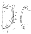
- Fig. 19 is a rear elevational view of the lumbar pad;
- Fig. 20 is a top plan view of the lumbar pad;
- Fig. 21 is a side elevational view of the lumbar pad;
- Fig. 22 is a top plan view of the lumbar cam;
- Fig. 22b is sectional view of the lumbar cam taken along XXIIB-XXIIB;
- Fig. 22c is sectional view of the lumbar cam taken along XXIIC-XXIIC;
- Fig. 22d is sectional view of the lumbar cam taken along XXIID-XXIID;
- Fig. 23 is a side elevational view of the lumbar cam;
- Fig. 24 is a top plan view of the seat frame;
- Fig. 25 is a bottom plan view of the seat frame;
- Fig. 26 is a perspective view of the seat carrier;
- Fig. 27 is a sectional view of the seat carrier taken along line XXVII-XXVII of Fig. 26;
- Fig. 28 is a partially exploded perspective view of the armrest assembly;
- Fig. 29 is a top plan view of the stretcher;
- Fig. 30 is a partially exploded perspective view of a single armrest;
- Fig. 31 is an enlarged view of area XXXI of Fig. 28;
- Fig. 32 is a sectional view of an armrest showing the interconnection of portions of the armrest adjustment mechanism;
- Fig. 33 is a sectional view of an armrest showing portions of the armrest adjustment mechanism with the tube in the uppermost position;
- Fig. 34 is a sectional view of an armrest showing portions of the armrest adjustment mechanism with the tube in the lowermost position;
- Fig. 35 is bottom perspective view of the upper plug;
- Fig. 36 is a sectional view of the upper plug taken along line XXXVI-XXXVI;
- Fig. 37 is a sectional view of the pivot bearing;
- Fig. 38 is a top plan view of the lower plug;
- Fig. 39 is a sectional view of the lower plug taken along line XXXIX-XXXIX of Fig. 38;
- Fig. 40 is a side elevational view of the plunger;
- Fig. 41 is a perspective view of the controls and control housing of the control mechanism;
- Fig. 42 is an exploded perspective view of the controls and control housing of the control mechanism;
- Fig. 43 is a side elevational view of the chair with portions removed to show the tension control linkage;
- Fig. 44 is a bottom plan view of the chair with portions removed to show the tension control linkage;
- Fig. 45 is a perspective view of portions of the chair showing the interconnection of the tension springs between the crankshaft and the spring plate;
- Fig. 46 is a sectional view of the control mechanism showing the cam and lever interaction of the tension control mechanism;
- Fig. 47 is a sectional view of the control mechanism showing the internal components of various control mechanisms;
- Fig. 48 is a sectional view of the control mechanism showing the internal components of the recline limit control mechanism;
- Fig. 49 is a top plan view of a portion of the seat frame with portions removed to show the interaction of the trackway and the stop;
- Fig. 50 is sectional view of a portion of the chair showing the height control wing assembled adjacent the toggle switch;
- Fig. 51 is front elevational view of the chair with the load bearing fabric and control mechanisms removed;
- Fig. 52 is right side elevational view of the chair with the load bearing fabric and control mechanisms removed;
- Fig. 53 is left side elevational view of the chair with the load bearing fabric and control mechanisms removed;
- Fig. 54 is top plan view of the chair with the load bearing fabric and control mechanisms removed; and
- Fig. 55 is bottom plan view of the chair with the load bearing fabric and control mechanisms removed.
-
- A chair in accordance with a preferred embodiment of the present invention is shown in Figs. 1-2 and 51-55, and generally designated 10. In a preferred embodiment, the load bearing surfaces of the
chair 10 are defined by load bearing fabric rather than conventional cushion and fabric constructions. Thechair 10 is, however, illustrated with the load bearing fabric removed in all but Fig. 1 to show the structure of the present invention. The loading bearing fabric attachment of the preferred embodiment is described in detail in U.S. Patent Application Serial No. 09/769,967, entitled LOAD BEARING FABRIC ATTACHMENT AND ASSOCIATED METHOD, which was filed on January 25, 2001, by Timothy P. Coffield et al, which is incorporated herein by reference. Although the present invention is described in connection with a chair incorporating load bearing fabric, the present invention is well suit for use in other constructions, for example, conventional cushion and fabric construction. - In general, the
chair 10 includes aseat 12, a back 14 and anarmrest assembly 16 mounted atop a height-adjustable pedestal 18. Theseat 12 and back 14 are movably mounted upon arecliner mechanism 20 that permits the back 14 to recline and theseat 12 to shift forwardly and rearwardly in concert with reclining movement of the back 14 (See Figs. 1, 18 and 52). Referring now to Fig. 18, alumbar support 30 is movably mounted to the back 14 in the lumbar region. Thelumbar support 30 is height-adjustable by movement of the lumbar support in a vertical track and is depth-adjustable by rotation of a lumbar cam. As perhaps best shown in Figs. 1 and 18, thearmrest assembly 16 is mounted atop thepedestal 18 so that it does not move with theseat 12 and back 14. Thearmrest assembly 16 includes a pair ofadjustable armrests seat 12. Therecliner mechanism 20 is mounted atop thepedestal 18 so that adjustment of the height of thepedestal 18 results in adjustment of theseat 12, back 14 andarmrest assembly 16. Referring now to Figs. 41 and 43, thechair 10 includes acontrol mechanism 26 that permits push-button control of the height of thechair 10, rotational control of the tension of the resilient back recliner mechanism and multi-positional lever control of the limit of the resilient back recliner mechanism. Thechair 10 further includes a modularupper back portion 90 that can be replaced by alternative modular back portions, such as upper back portion 90' shown in phantom lines in Fig. 2, to vary the overall shape of the back 14. - As noted above, the
seat 12, back 14 andarmrest assembly 16 are mounted atop a height-adjustable pedestal 18. As shown in Fig. 1, thepedestal 18 preferably includes fivelegs 32 terminating incasters 34 and asupport column 36 extending upwardly from thelegs 32. Thesupport column 36 is a generally conventional height-adjustable support column having telescopic upper 38 and lower 40 tubes. Although not shown, a spring or other biasing device is disposed within thelower tube 40 beneath theupper tube 38 to bias theupper tube 38 in an extended position. Thesupport column 36 also includes a generally conventional height actuator (not shown) for controlling the height of thecolumn 36 and hence the height of theseat 12. The height actuator (not shown) is contained within thesupport column 36 and includes atoggle switch 37 that protrudes from the upper end of theupper tube 38. Actuation of thetoggle switch 37 releases the locking mechanism of the height actuator, thereby permitting adjustment of the height of thesupport column 36 in a conventional manner. The height actuator is operated by theheight control mechanism 160, as will be described in more detail below. The describedpedestal 18 is merely exemplary, and it can be replaced by any of a wide variety of conventional pedestals as desired. - The
seat 12, back 14 andarmrest assembly 16 are mounted to thepedestal 18 upon arecliner mechanism 20. Therecliner mechanism 20 permits the back 14 to recline while linking theseat 12 to the back 14 so that the seat slides forwardly and rearwardly as the back 14 moves. The general operation of therecliner mechanism 20 is similar to that of the mechanism disclosed in U.S. Patent 4,842,333 to Meiller, which is incorporated herein by reference. Therecliner mechanism 20 generally includes a casting 42 that is mounted atop thesupport column 36 in a conventional manner. The casting 42 movably receives and supports theseat 12 and back 14 of thechair 10, in part by J-bar 50 as described in more detail below. As shown in Figs. 3-6, the casting 42 is a generally horizontally extending plate including a pair of roller bearing tracks 62 disposed on opposite lateral sides. Thetracks 62 open in opposite directions and are adapted to receive roller bearings mounted to the J-bar 50. Eachtrack 62 includes forwardly inclinedrear portion 66 and a rearwardlyinclined forward portion 68 that cooperatively define a shallow V-shaped channel. Therear portions 66 receive and shepherd therear roller bearings 60 of the J-bar 50. Theforward portions 68 receive and shepherd thefront roller bearings 58 of the J-bar 50. The configuration and operation of the J-bar 50 is described in more detail below. The casting 42 further includes a pair offront roller bearings 70 that support the front of theseat 12. Thefront roller bearings 70 are mounted to opposite lateral sides at the forward edge of the casting 42 and are preferably mounted upon pins 74. Thepins 74 are mounted, preferably by press-fitting, within bores 75 (See Fig. 6). The casting 42 also includes a centrally locatedmount 48 that fitted over theupper tube 38 of thesupport column 36. The casting 42 may be secured to theupper tube 38 by a set screw, snap ring, retaining clip or other conventional retaining device (not shown). The casting 42 also includes a plurality of mounting components for various control mechanisms. More specifically, the casting 42 includes aheight control clevis 272 adjacent to the mount 48 (See Fig. 4), arecline limit track 310 extending in a left/right direction across a portion of the casting 42 (See Fig. 4), and aspring plate mount 312 disposed at the rear of the casting 42 (See Fig. 3). Theheight control clevis 272 generally includes a pair of spaceduprights wing 264. Therecline limit track 310 generally includes a pair of spacedwalls 322 and 324, at least one of which preferably includes alongitudinally extending notch 314 that entraps a corresponding retainingrib 316 onstop 150. The function of these mounting components is described in more detail below. The casting 42 may also include top 44 and bottom 46 shrouds that enclose a portion of the casting 42. The casting 42 is preferably cast from aluminum or other conventional materials, but may be machined or otherwise manufactured as desired. - J-
bar 50 mounts the back 14 and the rear portion of theseat 12 to the casting 42. As shown in Figs. 7 and 8, the J-bar 50 includes a pair of L-shapedrecliner legs U-shaped back support 56. Afront roller bearing 58 and arear roller bearing 60 are mounted to the interior of eachleg corresponding front 80 and rear 82 pins. When assembled, theroller bearings front rollers 58 are received within thefront portions 68 and therear rollers 60 are received within therear portions 66. Eachleg seat mounting slot 78 that is aligned with the correspondingrear pin 82. In the preferred embodiment, theback support 56 defines a plurality of back mountingholes 84 for securing the back 14 to theback support 56 byscrews 85 or other conventional fasteners, as well as a plurality of lumbar mountingholes 83 for securing thelumbar support 30 to theback support 56 byscrews 81 or other conventional fasteners. The J-bar 50 is preferably cast from aluminum or other conventional materials, but may be machined or otherwise manufactured as desired. Thepins bar 50. - As perhaps best shown in Fig. 7, the back 14 generally includes a
back frame 86, aback carrier 88 and alumbar support 30. Referring now to Fig. 9, theback frame 86 is a peripheral framework receiving and providing structural support for theback carrier 88. Theback frame 86 defines achannel 72 extending entirely around the peripheral framework. Theback frame 86 defines a plurality ofslots 76 spaced around the base of thechannel 72 for use in securing theback carrier 88 to theback frame 86 as described in more detail below (See Fig. 11). Theback frame 86 also includes a plurality ofscrew bosses 64 for use in securing theback frame 86 to the J-bar 50 by screws. Theback frame 86 is preferably injection molded from a material having sufficient structural characteristics to support theback carrier 88 and the associated loads. For example, theback frame 86 may be manufactured from thirty percent glass-filled polypropylene or from nylon. - As noted above, the
back carrier 88 is secured to theback frame 86 within thechannel 72 and includes a modularupper back portion 90 that permits adjustment of the shape of the upper portion of the back 14. Theback carrier 88 is shown in Figs. 12 and 13 with the load bearing fabric removed to provide a clearer understanding of the subject matter of the present invention. Certain aspects of theback carrier 88 are described in detail in U.S. Patent Application Serial No. 09/769,967, which as noted above is incorporated herein by reference. Suffice it to say that theback carrier 88 includes a load bearing fabric 87 (See Fig. 1) that is stretched across and secured to theback carrier 88, preferably as an integral part of the back fabric carrier molding process. The phantom line FL shows the approximate position at which thefabric 87 enters thecarrier 88. Theback carrier 88 is fitted intochannel 72 and is preferably intersecured with theback frame 86 bysnaps 89 that are snap-fitted intoslots 76. Thesnaps 89 have hooked ends that securely interlock thesnaps 89 andslots 76. Theback carrier 88 can, however, be secured to theback frame 86 in alternative ways, for example, by screws (not shown). Although the present invention is described in connection with aback frame 86 supporting aload bearing fabric 87, the back frame could alternatively be a conventional cushioned back or other similar construction. Theback carrier 88 is preferably injection molded from a glass filled polypropylene or other similar materials. - As noted above, the
back carrier 88 is adapted to receive any of a number of modularupper back portions 90, 90'. To facilitate attachment of the desired modular upper back portion, theback carrier 88 includes a mountingplatform 110 that is recessed from the front surface of thecarrier 88 and includes a plurality ofscrew bosses 94 for screwing theupper back portion 90 to theback carrier 88. By way of illustration, a pair ofupper back portions 90 and 90' are shown in Figs.14-17. Upper back portion 90 (Figs. 14 and 15) is intended primarily for use on task seating, while upper back portion 90' (Figs. 16 and 17) is intended for use with executive seating. Each modularupper back portion 90, 90' includes afront surface 113, 113' that is preferably configured to align with the front surface of theback carrier 88 to provide a substantiallyuniform back 14. The twoupper back portions 90 and 90' includeidentical mounting platforms 92 and 92'. Only the mountingplatform 92 ofupper back portion 90 will be described in detail, it being understood that the mounting platform 92' of upper back portion 90', and other modular upper back portions, is essentially identical to mountingplatform 92. The mountingplatform 92 is shaped to mate with theplatform 110 of theback carrier 88, and includes a plurality ofscrew bosses 112 that align with thescrew bosses 94 of theback carrier 88. Theupper back portion 90 also includes a pair oftabs 114 that extend from opposite ends of the mountingplatform 92 and are trapped behind theback carrier 88. Thetabs 114 prevent the opposite ends of theupper back portion 90 from separating from theback carrier 88 under a rearward load. The desired upper back portion is mounted to theback carrier 88 simply by fitting thetabs 114 behind theback frame 88 and installing screws through thescrew bosses 94 in theback carrier 88 into thescrew bosses 112 in theupper back portion 90. If desired, the modular upper back portions could be secured to theback carrier 88 by other forms of attachment. For example, theupper back portion 90 and backcarrier mounting platform 110 may be provided with snap-together fittings (not shown) that supplement or replace the screws. Although not shown, the upper back portion can be padded and upholstered as desired. - The back 14 also includes a
lumbar support 30 that permits adjustment of the contour of the back 14 in the lumbar region. Referring now to Figs. 7 and 18-23, thelumbar support 30 generally includes alumbar pad 120 and alumbar cam 122 that are mounted to the rear of theback frame 86. Thelumbar pad 120 andlumbar cam 122 are mounted for vertical movement to permit adjustment of the vertical position of thelumbar support 30. Thelumbar pad 120 generally includes aplastic insert 300 and aurethane overmold 302 that is molded over theinsert 300. Although theinsert 300 is not illustrated separately, the profile of theinsert 300 is shown in broken lines in Fig. 19. Theinsert 300 provides thelumbar pad 120 with the desired level of rigidity and structural integrity. Theinsert 300 extends the entire length of thelumbar pad 120 and generally includes a plurality ofdiscs 304 positioned between a pair ofclevises 132. Thecenter portion 305 of eachdisc 304 is exposed through theovermold 302 for engagement with thecorresponding lobe lumbar cam 122. Theclevises 132 are located at opposite ends of theinsert 300 to receive opposite ends of thelumbar cam 122. Theinsert 300 also includes a pair offlanges 134 inwardly from eachclevis 132. Theflanges 134 cooperate with corresponding ribs on thelumbar cam 122 to bias thelumbar cam 122 in one of four distinct positions. Theurethane overmold 302 is substantially resilient providing thelumbar pad 120 with the desired cushioning. Thelumbar cam 122 is rotatably mounted to thelumbar pad 120, such that it can be rotated to provide the flexible lumbar pad 120 (and consequently the lumbar region of the back 14) with different shapes. Referring now to Figs. 22 and 23, thelumbar cam 122 generally includes a pair ofknobs 138 located on opposite ends of ashaft 140. Theshaft 140 includes three spacedlobes shaft 140. Thelobes lumbar cam 122. The preferred cross-sectional shapes of thelobes lobes lobes lobes outer lobes center lobe 144 is provided with the same height as in the second position, providing substantial support in the center of the lumbar region and greater support in the outer portions of the lumbar region. It should be noted that the number and shape of the lobes may vary from application to application to provide the lumbar with the desired adjustability. Thelumbar cam 122 is preferably injection molded from a substantially rigid polymeric material, such as acetal. The material is selected to provide thelumbar cam 122 will a limited degree of flexibility under conventional loads. Theknobs 138 are preferably overmolded with a softer rubber or polymeric material, such as kraton, to provide the desired feel. Thelumbar support 30 may be painted using conventional in-mold coating techniques. For example, thelumbar pad 120 and/orlumbar cam 122 can be painted by applying an in-mold paint to the interior surfaces of the mold parts prior to the injection molding process so that the paint is molded directly in place on the component. - Referring now to Figs. 7 and 18, the
lumbar pad 120 andlumbar cam 122 are secured to theback frame 86 bybrackets brackets screws 81 or other conventional fasteners, and each defines a vertically extendingchannel 128 that receives thelumbar pad 120 and thelumbar cam 122. Thelumbar pad 120 and thelumbar cam 122 are slidably entrapped within thechannels 128. Eachbracket vertical adjustment flange 130 that extends along thechannel 128. As a result of their interference, theribs 136 arranged along theflange 130 function to bias the lumbar 120 andlumbar cam 122 in one of seven predetermined vertical positions. The described brackets are merely exemplary and may be varied from application to application to provide the lumbar with the desired adjustability. For example, the location of the brackets, the size of the channel and the number, size and shape of vertical adjustment flanges may vary to alter the adjustability profile of the lumbar support. - As noted above, the rear of the
seat 12 is operatively connected to the J-bar 50 and the front of the seat is operatively connected to the casting 42, whereby theseat 12 slides forwardly and rearwardly as the back 14 reclines and returns to the upright position, respectively. Referring now to Fig. 3, theseat 12 generally includes aseat frame 98 and aseat carrier 100 mounted to theseat frame 98. As shown in Figs. 24 and 25, theseat frame 98 is generally concave, including aperipheral portion 96 defining achannel 97 for receiving theseat carrier 100. Theseat frame 98 includes a pair of downwardly extending mountingposts 102 disposed toward opposite lateral sides of theframe 98. The mountingposts 102 are fitted within theseat mounting slots 78 and are pivotally secured to therear pins 82 by mounting caps 95 (See Figs. 3 and 52). The front of theframe 86 is movably mounted to the casting 42 by a track and roller assembly. More specifically, theseat 12 includes roller tracks 104 disposed on opposite lateral sides of theseat frame 98. Thetracks 104 entrap and are operatively interfitted with thefront roller bearings 70 of the casting 42. As a result, the seat frame 98 (and hence the seat 12) is capable of forward and rearward movement with respect to the casting 42. Thetracks 104 are preferably pre-manufactured and secured to theseat frame 98 by interaction ofribs 107 and lockingtabs 99, which are integrally formed with theseat frame 98. Thetabs 99 are preferably snap-fitted into correspondingslots 109 in thetracks 104. Alternatively, thetracks 104 may be secured by screws, bolts or other conventional fasteners. Theseat frame 98 also includes atrackway 106 that interacts with the reclinelimit control mechanism 28 to adjustably limit the rearward recline of the back 14. Thetrackway 106 includes a plurality of offsetsteps 108a-e extending downwardly from the undersurface of theseat frame 98. In operation, this mechanism permits the user to set the maximum rearward recline of the back 14 to one of a plurality of different settings. In the illustrated embodiment, the reclinelimit control mechanism 28 provides five degrees of adjustment, one defined by each of the offsetsteps 108a-e. Operation of the reclinelimit control mechanism 28 is described in more detail below. Thetrackway 106 is preferably molded directly into theseat frame 98, but may be separately manufactured and secure to theseat frame 98, if desired. Theseat frame 98 also includes acrankshaft mount 162 for mounting thecrankshaft 162 of the tension linkage. Thecrankshaft mount 162 includes threeseparate portions 162a, 162b and 162c that receive the opposite ends and center portion of thecrankshaft 164. Thecrankshaft 164 is snap-fitted into center portion 162b. Opposite ends of thecrankshaft 164 are rotatably received inend portions 162a and 162c. Theseat frame 98 further includes a Z-bar mount 380 for mounting the Z-bar 352 of the tension linkage. The Z-bar mount 380 includes threeseparate portions 380a, 380b and 380c.Portions 380a and 380c rotatably receive end portions of the Z-bar 352. The Z-bar 352 is snap-fitted into center portion 380b. Operation of thecrankshaft 164, Z-bar 352 and the tension control linkage is described in more detail below. Theseat frame 98 is preferably injection molded from a material having sufficient structural characteristics to support theseat carrier 100 and the associated loads. For example, theseat frame 98 may be manufactured from thirty percent glass-filled polypropylene or from nylon. - The
seat carrier 100 is secured to theseat frame 98 within thechannel 97. Theseat carrier 100 is shown in Figs. 26 and 27. Certain aspects of theseat carrier 100 are described in detail in U.S. Patent Application Serial No. 09/769,967, which as noted above is incorporated herein by reference. Like theback carrier 88, theseat carrier 100 includes a load bearing fabric 101 (See Fig. 1) that is stretched across and secured to theseat carrier 100, preferably as an integral part of the seat carrier molding process. Theseat carrier 100 is fitted intochannel 97 and is preferably intersecured with theseat frame 98 bysnaps 103 that are snap-fitted into correspondingslots 105 in the base ofchannel 97. Thesnaps 103 preferably include a hooked end to securely interlock theseat carrier 100 with theseat frame 98. Theseat carrier 100 is preferably injection molded from glass filled polypropylene or other similar materials. - The
seat 12 is biased in its rearmost position (with respect to the casting 42) by a pair of recline tension springs 246. Fig. 45 shows the casting 42, thecrankshaft 164 and the tension springs 246. Theseat frame 98 and other components are removed to provide a clear view of these components. It should be noted that while Fig. 45 shows thecrankshaft 164 "floating" in space, it is actually snap-fitted to theseat frame 98 as described above and shown in Fig. 25. The recline tension springs 246 extend between thecrankshaft 164 on theseat frame 86 and thespring plate mount 312 on the casting 42. As described in more detail below, the amount of pre-tension on therecline tension spring 246 can be selectively varied by pivoting thecrankshaft 164 through operation of thetension control knob 250 and associated linkage. - The
armrest assembly 16 is mounted to the casting 42 and generally includes left 22 and right 24 armrests secured to opposite ends of a cross stretcher 170 (See Fig. 28). Thearmrests cross stretcher 170 and anarmpad 174 mounted to theupright 172. Eacharmpad 174 includes a mountingplate 175 that is secured to the undersurface of thearmpad 174 using fasteners or other conventional attachments. With reference to Fig. 29, thecross stretcher 172 is horizontally extending member that is mounted directly to the casting 42 at mountingsurface 176. Opposite ends 171 and 173 of thecross stretcher 172 are turned upwardly to define a pair of upright mounts 178. The upright mounts 178 are somewhat diamond shaped in cross-section. Theuprights 172 are mounted to the upright mounts 178, for example, byscrews 180, and are somewhat diamond shaped in cross-section to match the shape of themounts 178. Theuprights 172 are essentially hollow providing a void 182 for containing the armrest adjustment mechanism 184. - The armrest adjustment mechanism 184 will be described with reference to Figs. 30-40. Because the left 22 and right 24 armrests are substantially identical, only the
left armrest 22 will be described in detail. Referring now to Fig. 30, the armrest adjustment mechanism 184 generally includes anarm tube 190 movable mounted between aguide bearing 186 and aheight adjustment bearing 188. Atop plate 177 is mounted to the upper end of thetube 190, for example, by welding. Thetop plate 177 is secured to the mountingplate 175 by screws 179 (See Fig. 28). Acover 191 is slidably fitted over thetube 190 to close the upper end of the upright 172 is the assembled armrest. Theguide bearing 186 is fitted within the rear of the upright 172 and defines asemicircular recess 232 opening toward the front of theupright 172. The guide bearing further defines a pair ofalignment slots 233 that prevent rotation of thelower plug 222. Theguide bearing 186 includes an upwardly extendingcover mounting tab 187 for mountingcover 191 and a screw slot 286 for mounting the guide bearing 186 to theupright 172. The height adjustment bearing 188 is fitted within the front of the upright 172 and defines asemicircular recess 234 opening toward the rear of theupright 172. Therecesses tube 190. Accordingly, thetube 190 is permitted to travel vertically within the upright 172 between thebearings notches 238. The upper surface 237 of eachnotch 238 is preferably inclined to provide ratcheting interaction with theplunger 228. The upper surface of the uppermost notch defines areset surface 238. Thereset surface 238 extends farther toward thetube 190 than the upper surfaces 237 of theother notches 238. As a result, thereset surface 238 retracts theplunger 228 into the reset position when thearmpad 174 is fully raised. The bottom surface of thelowermost notch 238 defines arelease surface 241 that moves theplunger 228 out of the reset position when thearmpad 174 is fully lowered. The operation of the reset mechanism will be described in more detail below. The height adjustment bearing 188 includes an upwardly extendingcover mounting tab 189 for mountingcover 191 and a screw slot 288 for mounting the height adjustment bearing 186 to theupright 172. - An
upper plug 192 is fitted within the bottom ofarm tube 190. Theupper plug 192 includes a pair of mountingarms 194 for securing theplug 192 to the tube 190 (See Figs. 31 and 35). More specifically, theupper plug 192 is secured to thearm tube 190 by apin 198 extending throughholes 200 defined in thetube 190 andholes 202 defined in the mountingarms 194. Theupper plug 192 defines acentral bore 196 for rotatably securing a pivot bearing 204 to the undersurface of theupper plug 192 and anarcuate slot 224 for shepherding rotational movement of the pivot bearing 204 through interaction withpin 216, as described below. Theslot 224 preferably extends through an approximately 90-degree arc, thereby providing the armrest with approximately 90 degrees of rotational movement. The length and position of theslot 224 can be varied to alter the range of motion of the armrest. As shown in Fig. 35, theslot 224 includes a pair of smallrounded protrusions 225 that extend into theslot 224. Thepivot bearing 204 is generally disc-shaped and includes a centrally locatedshaft 206 that is fitted within thecentral bore 196 of the upper plug 192 (See Figs. 31 and 32). Theshaft 206 is fitted withinbore 205 and retained by retaining clip218. Theshaft 206 defines agroove 208 that receives aretaining clip 210 for intersecuring theupper plug 192 andpivot bearing 204. The pivot bearing 204 also defines a downwardly opening spring bore 212 and apin bore 214. Alimit pin 216 is fitted within the pin bore 214. Thelimit pin 216 extends upwardly into theslot 224 in theupper plug 192 to shepherd rotational movement of the armrest and provide a tactile response when the armrest is rotated past theprotrusions 225 into one of three desired positions. Thelimit pin 216 is preferably press-fitted into place inbore 214. Areset spring 220 is fitted withinspring bore 212. The function of thereset spring 220 will be described below. The pivot bearing 204 further defines a pair of screw holes 226. Alower plug 222 is secured to the undersurface of the pivot bearing 204, preferably byscrews 229 extending throughholes 244 in thelower plug 222 intoscrew holes 226 in thepivot bearing 204. Thelower plug 222 is generally disc shaped having an outer diameter substantially identical to the outer diameter of thetube 190. Thelower plug 222 defines aplunger slot 223 extending along a portion of a diameter of theplug 222 and alocking recess 227 extending downwardly from theplunger slot 224. Thelower plug 222 includes a pair of vertically extendingribs 282 that are slidably fitted intoslots 233 in the guide bearing 186 to prevent rotation of thelower plug 222. Aplunger 228 and aspring 230 are fitted within theplunger slot 223. Theplunger 228 includes an inclinedfront surface 240 that is rounded to correspond with the curvature of the height adjustment bearing 188 and a downwardly extending catch 242 (See Fig. 40) that is adapted to selectively fit into lockingrecess 227. Thespring 230 biases theplunger 228 toward thenotches 238 in theheight adjustment bearing 188. - Operation of the armrest adjustment mechanism 184 will now be described in connection with Figs. 32-34. Figs. 32 and 34 show the armrest 22 in the bottom position. The
armrest 22 is raised simply by lifting upwardly on thearmpad 174. Interaction of theinclined surface 240 of theplunger 228 and the inclined surfaces 237 of thenotches 238 causes theplunger 228 to retract into thelower plug 222 in a ratchet-like manner as thearmrest 22 is raised. The interaction retracts the plunger 228 a sufficient distance to permit theplunger 228 to clear thenotches 238, but not a sufficient distance for thecatch 242 to align with thelocking recess 226. Thespring 230 returns theplunger 228 to the extended position as eachnew notch 238 is reached. Because the lower surfaces of theplunger 228 andnotches 238 are substantially parallel, downward movement of the armrest is precluded unless theplunger 228 is locked in the reset position. When the armrest 22 has reached its top position (See Fig. 33), further upward movement locks theplunger 228 into the reset position. More specifically, theinclined surface 239 at the top of theuppermost notch 238 causes theplunger 228 to retract farther than theother notches 238. Theplunger 228 retracts until thecatch 242 is in alignment with thelocking recess 227. Once aligned, further interaction between theplunger 228 and thesurface 239 moves theplunger 228 downwardly causing thecatch 242 to enter thelocking recess 227. Thereset spring 220 provides a constant downward force on theplunger 228 pushing and holding thecatch 242 in thelocking recess 227. This locks theplunger 228 in the retracted position where it is disengaged from thenotches 238, thereby permitting the armrest 22 to be lowered. Once thearmrest 22 is fully lowered (See Fig. 34), theplunger 228 engages thereset surface 241 at the base of thelowermost notch 238. This forces theplunger 228 upward with respect to thelower plug 222. Once theplunger 228 is lifted a sufficient distance for thecatch 242 to disengage from the lockingrecess 226, theplunger spring 230 returns theplunger 228 to the extended position. The armrest 22 can then be lifted to the desired height as described above. - The armrest adjustment mechanism 184 also permits manual rotational movement of the armrest. When the armrest is rotated, the
tube 190 and attachedupper plug 192 rotate aboutshaft 206 of the pivot bearing 204, while the pivot bearing 204 andlower plug 22 remain stationary with respect to theupright 172. Thelimit pin 216 and slot 224 cooperate to limit the range of movement of the armrest. As noted above, theslot 224 extends through an arc of approximately 90 degrees. Because this arc is centered, the armrest is permitted to rotate left or right a distance of approximately 45 degrees from center. Thelimit pin 216 and slot 224 also cooperate to provide a tactile response when the armrest is centered or at its leftmost or rightmost extremes. More specifically, theprotrusions 225 interfere with movement of thelimit pin 216 through theslot 224 to resist, but not prevent, rotational movement of the armrest between the center, leftmost and rightmost positions. - As noted above, the
control mechanism 26 permits adjustment of a variety of components of thechair 10. Thecontrol mechanism 26 generally includes atension control mechanism 118 that controls the amount of resistance to reclining movement of the back 14, a reclinelimit control mechanism 28 that controls the rearward limit on reclining movement of the back 14 and aheight control mechanism 160 that controls the height of the support column 36 (and consequently the seat 12). Thecontrol mechanism 26 includes acontrol housing 156 that is mounted to theseat frame 98. Thecontrol housing 156 includes anintegral throat 157. Thecontrol housing 156 is preferably configured to snap fit into place on theseat frame 98, but it can be secured using fasteners or other conventional mechanisms. - The
tension control mechanism 118 includes atension knob 250 that is rotated to control the tension at which the back 14 reclines. As noted above, the tension in the back recline is created by a pair of recline tension springs 246 that extend between theseat frame 98 and the casting 42. As perhaps best shown in Fig. 45, the tension springs 246 extend between spring mounting plate 312 (secured to casting 42) and crankshaft 164 (secured to seat frame 98). The recline tension springs 246 are arranged to resist forward movement of theseat frame 98 with respect to the casting 42 and to bias theseat frame 98 in the rearmost position. Thetension knob 250 is operatively linked to therecline tension spring 246 by a linkage. The linkage includes acam 280 that is rotatably mounted withinhousing 156. Thecam 280 includes anintegral shaft 350 that extends through thethroat 157 of thehousing 156 and is secured to thetension knob 250 so that rotation of theknob 250 the causes rotation ofcam 280. The linkage further includes alever 254 pivotally mounted in thehousing 156 adjacent to thecam 280 so that rotational movement of thecam 280 results in pivotal movement of the lever 254 (See Fig. 46). As perhaps best shown in Figs. 43 and 44, a Z-bar 352 is pivotally mounted to the undersurface of theseat frame 98 with its first end in operative connection with thelever 254. As a result, movement of thelever 254 results in pivotal movement of the Z-bar 352. The second end of the Z-bar 352 is operatively connected to awire 356. Thewire 356 extends between and operatively interconnects the Z-bar 352 and thecrankshaft 164 so that pivotal movement of the Z-bar 352 results in pivotal movement of thecrankshaft 164. Pivotal movement of thecrankshaft 164 varies the length of the tension springs 246, thereby varying the amount of pre-tension in thesprings 246 and consequently the amount of tension in the back recline. The unique construction of thetension control mechanism 118 is fully adjustable through only approximately 180 degrees of rotation of thetension knob 250. - The recline
limit control mechanism 28 functions to control the limit of rearward recline in theback 14. The reclinelimit control mechanism 28 includes a reclinelimit control lever 148 positioned where it is easily accessible to the occupant, preferably about thethroat 157 of thehousing 156. Thelever 148 preferably includes anintegral rotor 149. Acontrol cable 152 is mounted to therotor 149 and astop 150 mounted to thecontrol cable 152. As shown in Fig.48, the first end of the cable sheath 154 is mounted to thecontrol housing 156 atneck 366 and the second end of the cable sheath 154 is mounted to the casting 42 by aretainer 368. Although not shown, theretainer 368 is snap-fitted into place on the casting 42 whereby thestop 150 is positioned in the path along which thetrackway 106 will travel when theseat frame 98 moves. If desired, adetent spring 370 may be fitted into thehousing 156 is engagement with therotor 149 to provide tactile feedback, such as a snap, when thelever 148 is properly positioned in one of its five positions. Aspring 158 is preferably fitted over the second end of thecable 152 to bias thestop 150. Thestop 150 is slidably fitted withinstop track 310 and includes a retainingrib 316 that is fitted withinnotch 314 inwall 322 or 324. In operation, pivotal movement of thelever 148 results in linear movement of thestop 150 with respect to thetrackway 106. More specifically, movement of thelever 148 causes therotor 149 to rotate withinhousing 156, thereby extending or retracting thecable 152. This in turn causes thestop 150 to move linearly along thetrack 310 to align withdifferent steps 108a-e in thetrackway 106. Lines A, B, C, D and E of Fig. 49 show the five different positions of thestop 150. As the back 14 is reclined, theseat frame 98 moves with respect to the casting 42 until thetrackway 106 engages thestop 150. Once thetrackway 106 and stop 150 engage, further movement of theseat frame 98, and consequently rearward recline, is prevented. In the preferred embodiment, thetrackway 106 and thestop 150 are configured so that the first position provides no seat travel (See Fig. 49, line A), the second position provides one inch of seat travel (See Fig. 49, line B), the third position provides two inches of seat travel (See Fig. 49, line C), the fourth position provides three inches of seat travel (See Fig. 49, line D) and the fifth position provides four inches of seat travel (See Fig. 49, line E). The configuration of thetrackway 106, for example, the number and location ofstep 108a-e may vary from application to application to provide the desired range of adjustability. - The
height control mechanism 160 includes a push-button 256 mounted within thetension knob 250. Thepush button 256 includes anintegral shaft 258 that extends into thecontrol housing 156 through the center of thetension knob 250 and thecam 280. Theshaft 258 is engaged with arotor 260, and more particularly withsurface 274 ofrotor 260. Aspring 262 is disposed aboutshaft 258 to bias thepush button 256 in an outward position. Therotor 260 is rotatably mounted within thecontrol housing 156 to rotate in response to actuation of the push-button 256. Acontrol cable 266 is secured about therotor 260 so that rotation of therotor 260 results in extension and retraction of thecable 266. Thecable 266 is connected to awing 264 so that extension and retraction of thecable 266 results in movement of thewing 264. Thewing 264 is movable mounted within a fitting 380 that is secured to thecable sheath 270. A spring 276 is disposed about the second end of thecable 266 between thesheath 270 and thewing 264 to bias thewing 264 in the extended position. The fitting 380 is mounted to theheight control clevis 272 on casting 42 with thewing 264 located in operative engagement with thetoggle switch 37 of the support column height actuator (not shown). As a result, movement of thewing 264 operates thetoggle switch 37 and consequently the height actuator. In operation, depression of the push-button 256 causesshaft 258 to engage and apply force to surface 274, thereby causing clockwise (when view from the perspective shown in Fig. 47) rotational movement of therotor 260 about its axis. Clockwise rotational movement of therotor 260 wraps thecable 266 around therotor 260 causing it to retract. This results in inward linear movement of thewing 264 and actuation of thetoggle switch 37. Actuation of thetoggle switch 37, releases the locking mechanism of the support column height actuator (not shown), thereby permitting adjustment of the height of thesupport column 36. The height actuator (not shown) of thesupport column 36 functions in a generally conventional manner, raising the upper tube 38 (and consequently theseat 12 and back 14) through an internal spring (not shown) and lowering the upper tube 38 (and consequently theseat 12 and back 14) through downward force applied by the occupant. When theseat 12 is in the desired position, the user releases pushbutton 256. Thebutton spring 262 and wing spring 276 extend thecable 266 and return thepush button 256 to the outward position. This returnstoggle switch 37 to the locked position, thereby engaging the locking mechanism of the support column height actuator (not shown) and securing theseat 12 and back 14 at the selected height. - The above description is that of a preferred embodiment of the invention. Various alterations and changes can be made without departing from the spirit and broader aspects of the invention as defined in the appended claims, which are to be interpreted in accordance with the principles of patent law including the doctrine of equivalents. Any reference to claim elements in the singular, for example, using the articles "a," "an," "the" or "said," is not to be construed as limiting the element to the singular.
Claims (47)
- A chair comprising:a recliner mechanism;a back movably mounted to said recliner mechanism, said recliner mechanism permitting said back to recline under a force to a selectable limit;a seat movably mounted to said recliner mechanism and operatively linked to said back, whereby said seat moves forwardly as said back reclines;a recline limit control mechanism for adjustably controlling said selectable limit, said control mechanism including a trackway and a stop, at least one of said trackway and said stop traveling forwardly along a path as said seat moves forwardly, said selectable limit being defined by engagement of said stop with said trackway, said stop being movable with respect to said trackway such that said selectable limit is adjusted by movement of said stop.
- The chair of claim 1 wherein said trackway includes a plurality of laterally offset steps.
- The chair of claim 2 wherein said offset steps are offset from one another in a lateral direction and in a longitudinal direction.
- The chair of claim 3 wherein said offset steps are offset from one another in a lateral direction and in a longitudinal direction.
- The chair of claim 4 wherein said trackway is carried by said seat and said stop is mounted to said recliner mechanism.
- The chair of claim 5 wherein said stop is slidably mounted within a track on said recliner mechanism.
- The chair of claim 6 wherein said control mechanism includes a lever, a rotor mounted to said lever and a cable mounted to said rotor, said stop being mounted to said cable, whereby movement of said lever results in movement of said stop.
- The chair of claim 7 further comprising a bias means for biasing said seat in a rearward position at a tension, said bias means including a biasing element extending between said recliner mechanism and said seat, said biasing element having a pre-tension; and
a tension control mechanism for adjustably controlling said tension by selectively varying said pre-tension in said biasing element. - The chair of claim 8 wherein said tension control mechanism includes a tension knob that is rotatably mounted to said chair, said tension knob being operatively linked to said biasing element such that rotation of said tension knob results in variation in said pre-tension in said biasing element.
- The chair of claim 9 wherein said tension knob includes a shaft, said lever being rotatably mounted about said shaft with said lever disposed adjacent to said tension knob.
- The chair of claim 10 further comprising an adjustable height support column; and
a height control mechanism for selectively adjusting a height of said support column, said height control mechanism including a push button mounted within said tension knob. - A chair comprising:a recliner mechanism;a back mounted to said recliner mechanism, said back being reclinable between a default position and a reclined position under a rearward force;a seat movably mounted to said recliner mechanism and operatively linked to said back, whereby said seat moves forwardly from a rearward position to a forward position as said back moves from said default position to said reclined position;a bias means for biasing said seat in said rearward position at a tension, said bias means including a biasing element extending between said recliner mechanism and said seat, said biasing element having a pre-tension;a tension control mechanism for adjustably controlling said tension by selectively varying said pre-tension in said biasing element.
- The chair of claim 12 wherein said tension control mechanism includes a control knob rotatably mounted to said chair, said control knob being operatively connected to said biasing element, wherein rotation of said control knob results in variation in said pre-tension in said biasing element.
- The chair of claim 13 wherein said control mechanism includes a cam mounted to said control knob whereby rotation of said control knob results in rotation of said cam, said cam being operatively connected to said biasing element, wherein rotation of said cam results in variation in said pre-tension in said biasing element.
- The chair of claim 14 wherein said control mechanism includes a pre-tension lever operatively linked to said cam, said pre-tension lever pivoting in response to rotation of said cam, said pre-tension lever being operatively connected to said biasing element, wherein pivoting of said pre-tension lever results in variation in said pre-tension in said biasing element.
- The chair of claim 15 wherein said control mechanism provides full adjustment of said tension by rotation of said control knob through no more than about 180 degrees.
- The chair of claim 16 wherein said recline mechanism permits said back to recline to an adjustable limit; and
further comprising a recline limit control mechanism for adjustably controlling said limit, said control mechanism including a trackway and a stop, at least one of said trackway and said stop traveling forwardly along a path as said seat moves forwardly, said selectable limit being defined by engagement of said stop with said trackway, said stop being movable with respect to said trackway such that said selectable limit is adjusted by movement of said stop. - The chair of claim 17 wherein said control knob is mounted upon a shaft protruding from a control housing, said recline limit control mechanism including a lever mounted over said shaft.
- The chair of claim 18 further comprising an adjustable height support column; and
a height control mechanism for selectively adjusting a height of said support column, said height control mechanism including a push button mounted within said tension knob. - A chair comprising:a pedestal having an adjustable height support column;a recliner mechanism mounted atop said support column;a back mounted to said recliner mechanism, said back being reclinable between a default position and a reclined position under a rearward force;a seat movably mounted to said recliner mechanism and operatively linked to said back, whereby said seat moves forwardly from a rearward position to a forward position as said back moves from said default position to said reclined position;a bias means for biasing said seat in said rearward position at a tension;a tension control mechanism having a control knob, said control knob being rotatable to selectively adjust said tension;a height control mechanism for selectively adjusting a height of said support column, said height control mechanism including a push button mounted within said control knob.
- The chair of claim 20 wherein said height control mechanism includes a wing movably mounted to said recliner mechanism, said push button operatively linked to wing such that actuation of said push button results in movement of said wing.
- The chair of claim 21 wherein said support column includes a toggle switch, said wing being operatively linked to said toggle switch, whereby movement of said wing results in actuation of said toggle switch.
- The chair of claim 22 wherein said support column includes an upper tube telescopically fitted within a lower tube, said toggle switch protruding from said upper tube.
- A chair comprising:a pedestal;a seat and back mounted atop said pedestal, said back including a load bearing fabric mounted within a frame; anda lumbar support mounted to said frame of said back, said lumbar support including a lumbar pad and a lumbar cam, said lumbar pad being substantially flexible and being disposed adjacent to said load bearing fabric in a lumbar region of said back, said lumbar cam including a lobe engaging said lumbar pad, said lobe having a radius that varies about said shaft, whereby rotation of said lumbar cam varies a contour of said lumbar pad and said lumbar region of said back.
- The chair of claim 24 wherein said lumbar cam is rotatably mounted to said lumbar pad.
- The chair of claim 25 wherein said lumbar pad includes a pair of clevises rotatably receiving opposite ends of said lumbar cam.
- The chair of claim 26 wherein said lumbar cam is mounted to said back for vertical movement.
- The chair of claim 27 wherein said lumbar cam is mounted to said back by a pair of brackets, each of said brackets defining a vertically extending channel, said lumbar cam being movable fitted within said channels.
- The chair of claim 28 wherein said lumbar pad includes a structural insert and a cushioning material overmolded onto said insert.
- The chair of claim 29 wherein said lumbar pad includes a flange and said lumbar cam includes a plurality of locating ribs, said flange disposed to engage said ribs.
- The chair of claim 30 wherein at least one of said brackets includes a plurality of protrusions extending into said channel to interfere with but not prevent movement of said lumbar cam within said channel.
- The chair of claim 31 wherein said lumbar cam includes a center lobe and a pair of outer lobes.
- The chair of claim 32 wherein each of said lobes has a radius that varies about said shaft.
- The chair of claim 33 wherein said lumbar cam is rotatable between four distinct positions, said lobes being configured to define four distinct lumbar contours at each of said four distinct positions.
- A chair comprising:a pedestal;a seat and a back mounted atop said pedestal, said back including a back frame, a back carrier mounted within said back frame and a load bearing fabric mounted within said back carrier, said back carrier defining an upper back mounting platform for receiving one of a plurality of modular upper backs; anda modular upper back mounted to said upper back portion mounting platform.
- The chair of claim 35 wherein said back carrier includes a front surface, said mounting platform being recessed from said front surface.
- The chair of claim 36 wherein said modular upper back includes a depth, said mounting platform being recessed from said front surface a distance substantially equal to said depth.
- The chair of claim 37 wherein said modular upper back includes opposite ends, said opposite ends of said upper back being interfitted with said mounting platform to preclude separation of said opposite ends of said upper back from said mounting platform when said upper back is under force.
- The chair of claim 38 wherein said mounting platform defines a plurality of screw bosses, said modular upper back including a plurality of screw holes aligned with said screw bosses of said mounting platform.
- A chair comprising:a pedestal;a seat and a back mounted atop said pedestal;an armrest assembly mounted atop said pedestal adjacent said seat, said armrest assembly including a tube movably secured to an upright and an armpad secured to said tube, said armrest assembly further including a ratchet mechanism for adjusting a height of said tube with respect to said upright, said ratchet assembly includes a plunger reciprocally carried by said tube and a plurality of notches defined by said upright, said ratchet assembly further including a biasing means for biasing said plunger into engagement with said notches.
- The chair of claim 40 wherein said ratchet mechanism includes a reset means for retaining said plunger in a retracted position out of engagement with said notches to permit said tube to be lowered with respect to said upright.
- The chair of claim 41 wherein said reset means includes a catch means for releasably retaining said plunger in a retracted position upon alignment of said plunger with said catch means, said reset means further including a surface retracting said plunger into alignment with said catch means when said tube is moved to its upper extreme with respect to said upright.
- The chair of claim 42 wherein said reset means further includes a second surface disengaging said plunger from said catch means when said tube is moved to its lower extreme with respect to said upright.
- The chair of claim 43 wherein said armrest assembly includes a pivot mechanism providing adjustment of an angle of said armpad by rotation of said tube with respect to said upright, said pivot mechanism including an upper member mounted to said tube and a lower member rotatably mounted to said lower member, said lower member being coupled to said upright so as to prevent rotation of said lower member with respect to said upright, said plunger being mounted within said lower member.
- The chair of claim 44 wherein said pivot mechanism further includes a means for defining a range of pivotal movement of said tube.
- The chair of claim 45 wherein said means for defining a range of pivotal movement of said tube includes a pin mounted to one of said upper member and said lower member, said pin extending into an arcuate slot in the other of said upper member and said lower member, said pin moving through said slot upon rotation of said tube.
- The chair of claim 46 wherein said means for defining a range of pivotal movement of said tube includes at least one protrusions extending into said arcuate slot to interference with but not prevent movement of said pin through said slot.
Priority Applications (1)
| Application Number | Priority Date | Filing Date | Title |
|---|---|---|---|
| EP06015987A EP1719435A1 (en) | 2001-01-25 | 2002-01-25 | Office chair |
Applications Claiming Priority (4)
| Application Number | Priority Date | Filing Date | Title |
|---|---|---|---|
| US769967 | 2001-01-25 | ||
| US09/769,967 US6842959B2 (en) | 2001-01-25 | 2001-01-25 | Load bearing fabric attachment and associated method |
| US883646 | 2001-06-18 | ||
| US09/883,646 US6688690B2 (en) | 2001-01-25 | 2001-06-18 | Office chair |
Related Child Applications (1)
| Application Number | Title | Priority Date | Filing Date |
|---|---|---|---|
| EP06015987A Division EP1719435A1 (en) | 2001-01-25 | 2002-01-25 | Office chair |
Publications (2)
| Publication Number | Publication Date |
|---|---|
| EP1226773A1 true EP1226773A1 (en) | 2002-07-31 |
| EP1226773B1 EP1226773B1 (en) | 2006-11-02 |
Family
ID=27118250
Family Applications (2)
| Application Number | Title | Priority Date | Filing Date |
|---|---|---|---|
| EP06015987A Withdrawn EP1719435A1 (en) | 2001-01-25 | 2002-01-25 | Office chair |
| EP02001138A Expired - Lifetime EP1226773B1 (en) | 2001-01-25 | 2002-01-25 | Office chair |
Family Applications Before (1)
| Application Number | Title | Priority Date | Filing Date |
|---|---|---|---|
| EP06015987A Withdrawn EP1719435A1 (en) | 2001-01-25 | 2002-01-25 | Office chair |
Country Status (9)
| Country | Link |
|---|---|
| US (1) | US7029071B2 (en) |
| EP (2) | EP1719435A1 (en) |
| JP (2) | JP3742017B2 (en) |
| CN (1) | CN1370490A (en) |
| AT (1) | ATE343949T1 (en) |
| CA (2) | CA2368923C (en) |
| DE (1) | DE60215709T2 (en) |
| ES (1) | ES2273926T3 (en) |
| TW (1) | TWI240621B (en) |
Cited By (6)
| Publication number | Priority date | Publication date | Assignee | Title |
|---|---|---|---|---|
| US6802566B2 (en) | 2000-09-28 | 2004-10-12 | Formway Furniture Limited | Arm assembly for a chair |
| EP1537804A1 (en) * | 2003-12-06 | 2005-06-08 | Bock 1 GmbH & Co. KG | Synchronised mechanism for an office chair |
| EP2070446A1 (en) * | 2007-12-11 | 2009-06-17 | Sedus Stoll AG | Office chair with adjustable backrest and means to limit the slope of the backrest |
| EP2508103A1 (en) * | 2011-04-08 | 2012-10-10 | Bock-1 GmbH & Co. KG | Seat holder for a chair |
| CN104023593A (en) * | 2011-11-04 | 2014-09-03 | 株式会社冈村制作所 | Chair |
| US11690457B2 (en) | 2020-02-04 | 2023-07-04 | Hni Technologies Inc. | Chair with flexible internal support |
Families Citing this family (47)
| Publication number | Priority date | Publication date | Assignee | Title |
|---|---|---|---|---|
| JP4750401B2 (en) * | 2004-10-29 | 2011-08-17 | 株式会社イトーキ | Chair |
| CN105832036B (en) * | 2005-03-01 | 2019-12-17 | 霍沃思公司 | Seat back with lumbar and pelvic supports |
| JP4844723B2 (en) * | 2006-03-28 | 2011-12-28 | コクヨ株式会社 | Chair |
| JP5013359B2 (en) * | 2006-03-28 | 2012-08-29 | コクヨ株式会社 | Chair |
| JP5004152B2 (en) * | 2006-03-28 | 2012-08-22 | コクヨ株式会社 | Chair |
| US8616641B2 (en) | 2006-10-04 | 2013-12-31 | Access Enterprise, Llc | Therapeutic back support and stabilization |
| US10842280B2 (en) | 2006-10-04 | 2020-11-24 | Access Enterprise, Llc | Therapeutic back support and stabilization |
| US20080084101A1 (en) * | 2006-10-04 | 2008-04-10 | Mark Powicki | Forward-biased postural chair |
| US7695067B2 (en) * | 2007-03-02 | 2010-04-13 | Goetz Mark W | Ergonomic adjustable chair |
| EP2017756A1 (en) * | 2007-07-20 | 2009-01-21 | BrainLAB AG | Method for displaying and/or processing or manipulating image data for medical purposes with gesture recognition |
| IT1395300B1 (en) * | 2008-10-22 | 2012-09-05 | Imarc Spa | ADJUSTMENT SYSTEM OF THE MUTUAL POSITION AMONG TWO FURNITURE PARTS.- |
| US8944507B2 (en) * | 2009-10-13 | 2015-02-03 | Herman Miller, Inc. | Ergonomic adjustable chair mechanisms |
| WO2011137120A1 (en) * | 2010-04-26 | 2011-11-03 | Haworth, Inc. | Manufacturing process for forming a chair back |
| JP5882684B2 (en) * | 2011-11-04 | 2016-03-09 | 株式会社岡村製作所 | Chair |
| US20140157939A1 (en) | 2011-12-09 | 2014-06-12 | Grand Rapids Controls Company, Llc | Release mechanism |
| KR101148032B1 (en) * | 2011-12-15 | 2012-05-24 | 주식회사 시디즈 | Apparatus for supporting a lumbar vertebrae for a chair |
| JP5490175B2 (en) * | 2012-05-15 | 2014-05-14 | コクヨ株式会社 | Chair |
| US11304528B2 (en) | 2012-09-20 | 2022-04-19 | Steelcase Inc. | Chair assembly with upholstery covering |
| USD697726S1 (en) | 2012-09-20 | 2014-01-21 | Steelcase Inc. | Chair |
| CN103799741B (en) * | 2012-11-01 | 2017-06-20 | 奥弗·巴查 | Backrest, seat unit and method |
| USD743712S1 (en) | 2013-03-15 | 2015-11-24 | Herman Miller, Inc. | Chair |
| CN106455821A (en) | 2014-04-17 | 2017-02-22 | Hni技术公司 | Chair and chair control assemblies, systems, and methods |
| US9861203B2 (en) * | 2015-03-05 | 2018-01-09 | A-Dec, Inc. | Seat assembly for task-oriented seating |
| US10194750B2 (en) | 2015-04-13 | 2019-02-05 | Steelcase Inc. | Seating arrangement |
| US11259637B2 (en) | 2015-04-13 | 2022-03-01 | Steelcase Inc. | Seating arrangement |
| JP6826043B2 (en) | 2015-04-13 | 2021-02-03 | スティールケース インコーポレイテッド | Seating structure |
| US10966527B2 (en) | 2017-06-09 | 2021-04-06 | Steelcase Inc. | Seating arrangement and method of construction |
| CN106880204A (en) * | 2015-12-16 | 2017-06-23 | 有限会社爱琳彩 | Radial type chair |
| US10463153B2 (en) | 2016-06-09 | 2019-11-05 | Steelcase Inc. | Seating arrangement |
| ES2595530B1 (en) * | 2016-08-10 | 2017-07-17 | Javier PERALES BOTÍA | NEW ERGONOMIC WORK STATION WITH MOVEMENT ASSISTANCE FOR HAIRDRESSERS |
| CN107187357B (en) * | 2017-05-31 | 2023-04-18 | 安道拓(重庆)汽车部件有限公司 | Armrest locking mechanism and automobile seat armrest with armrest locking mechanism |
| JP6900478B2 (en) * | 2017-06-20 | 2021-07-07 | コクヨ株式会社 | Chair |
| CN107136816B (en) * | 2017-06-30 | 2022-11-25 | 杭州飞思十工业设计有限公司 | Sitting posture correcting seat |
| WO2019139495A1 (en) * | 2018-01-15 | 2019-07-18 | Zoran Stajic | Joystick chair |
| CN108514264A (en) * | 2018-06-20 | 2018-09-11 | 昆山奇朗数码科技有限公司 | A kind of power seat |
| CN109131897A (en) * | 2018-07-04 | 2019-01-04 | 苏州频聿精密机械有限公司 | A kind of aero seat apparatus for adjusting position |
| CN109497751B (en) * | 2018-11-26 | 2024-07-16 | 陈敏 | Waist pad structure of chair seat |
| EP3927215A4 (en) | 2019-02-21 | 2023-03-15 | Steelcase Inc. | Body support assembly and methods for the use and assembly thereof |
| CN111657704A (en) * | 2019-03-05 | 2020-09-15 | 及桦实业股份有限公司 | Angle adjusting structure for supporting pad of armrest of chair |
| US11357329B2 (en) | 2019-12-13 | 2022-06-14 | Steelcase Inc. | Body support assembly and methods for the use and assembly thereof |
| DE102020126229B4 (en) | 2020-10-07 | 2022-06-30 | Bock 1 Gmbh & Co. Kg | Operating device for adjusting a backrest of an office chair |
| CN112617493B (en) * | 2020-12-22 | 2022-06-24 | 深圳东港嘉胜家具制造有限公司 | Chair with detachable seat |
| CN113125226B (en) * | 2021-04-16 | 2023-09-05 | 重庆医药高等专科学校 | Biological tissue slicer |
| CN113855276B (en) * | 2021-10-07 | 2023-03-10 | 北京华腾创新科技有限公司 | Operation chair |
| USD1041979S1 (en) * | 2021-10-18 | 2024-09-17 | Orangebox Limited | Seat and back unit for a task chair |
| USD1041935S1 (en) * | 2021-10-18 | 2024-09-17 | Orangebox Limited | Task chair |
| USD1014163S1 (en) * | 2021-10-18 | 2024-02-13 | Orangebox Limited | Back for a task chair |
Citations (4)
| Publication number | Priority date | Publication date | Assignee | Title |
|---|---|---|---|---|
| US4842333A (en) | 1987-08-14 | 1989-06-27 | Grammer Sitzsysteme Gmbh | Seat |
| EP0568233A1 (en) * | 1992-04-20 | 1993-11-03 | Steelcase Inc. | Cable actuated variable stop mechanism |
| US6000756A (en) * | 1997-03-12 | 1999-12-14 | Leggett & Platt, Inc. | Synchronized chair seat and backrest tilt control mechanism |
| US6086153A (en) * | 1997-10-24 | 2000-07-11 | Steelcase Inc. | Chair with reclineable back and adjustable energy mechanism |
Family Cites Families (11)
| Publication number | Priority date | Publication date | Assignee | Title |
|---|---|---|---|---|
| GB794138A (en) * | 1955-12-20 | 1958-04-30 | Res Interests Ltd | Improvements in or relating to reclining chairs |
| DE3781282T2 (en) * | 1987-10-24 | 1992-12-17 | Kokuyo Kk | LOUNGE CHAIR. |
| DE3930983C2 (en) * | 1989-09-16 | 1993-09-30 | Rolf Voelkle | Seating with an adjustable seat |
| US5314237A (en) * | 1992-02-12 | 1994-05-24 | Kimball International Marketing, Inc. | Reclining chair |
| US6296312B1 (en) * | 1995-02-21 | 2001-10-02 | Neutral Posture Ergonomics, Inc. | Armrest assembly |
| DE19543818C1 (en) * | 1995-11-24 | 1997-05-07 | Desanta | Chair with knee support |
| US6076892A (en) * | 1997-06-04 | 2000-06-20 | Knoll, Inc. | Multi-adjustable armrest assembly |
| US6139107A (en) * | 2000-03-17 | 2000-10-31 | Lee; Ching-Yang | Armrest adjusting mechanism |
| US6394553B1 (en) * | 2000-06-09 | 2002-05-28 | Knoll, Inc. | Adjustable armrest assembly with single adjustment lever |
| US6619746B2 (en) * | 2000-06-09 | 2003-09-16 | Haworth, Inc. | Height-adjustable rotatable chair arm |
| US6467842B1 (en) * | 2001-04-09 | 2002-10-22 | Aur Hann Co., Ltd. | Locating structure of a reclining leisure chair |
-
2002
- 2002-01-22 CA CA002368923A patent/CA2368923C/en not_active Expired - Fee Related
- 2002-01-22 CA CA002525902A patent/CA2525902A1/en not_active Abandoned
- 2002-01-23 TW TW091101033A patent/TWI240621B/en not_active IP Right Cessation
- 2002-01-25 JP JP2002016890A patent/JP3742017B2/en not_active Expired - Fee Related
- 2002-01-25 CN CN02102535A patent/CN1370490A/en active Pending
- 2002-01-25 EP EP06015987A patent/EP1719435A1/en not_active Withdrawn
- 2002-01-25 DE DE60215709T patent/DE60215709T2/en not_active Expired - Fee Related
- 2002-01-25 EP EP02001138A patent/EP1226773B1/en not_active Expired - Lifetime
- 2002-01-25 AT AT02001138T patent/ATE343949T1/en not_active IP Right Cessation
- 2002-01-25 ES ES02001138T patent/ES2273926T3/en not_active Expired - Lifetime
-
2003
- 2003-09-09 US US10/657,984 patent/US7029071B2/en not_active Expired - Fee Related
-
2005
- 2005-08-04 JP JP2005226292A patent/JP2006006965A/en not_active Withdrawn
Patent Citations (4)
| Publication number | Priority date | Publication date | Assignee | Title |
|---|---|---|---|---|
| US4842333A (en) | 1987-08-14 | 1989-06-27 | Grammer Sitzsysteme Gmbh | Seat |
| EP0568233A1 (en) * | 1992-04-20 | 1993-11-03 | Steelcase Inc. | Cable actuated variable stop mechanism |
| US6000756A (en) * | 1997-03-12 | 1999-12-14 | Leggett & Platt, Inc. | Synchronized chair seat and backrest tilt control mechanism |
| US6086153A (en) * | 1997-10-24 | 2000-07-11 | Steelcase Inc. | Chair with reclineable back and adjustable energy mechanism |
Cited By (11)
| Publication number | Priority date | Publication date | Assignee | Title |
|---|---|---|---|---|
| US6802566B2 (en) | 2000-09-28 | 2004-10-12 | Formway Furniture Limited | Arm assembly for a chair |
| US6817667B2 (en) | 2000-09-28 | 2004-11-16 | Formway Furniture Limited | Reclinable chair |
| US7798573B2 (en) | 2000-09-28 | 2010-09-21 | Formway Furniture Limited | Reclinable chair |
| EP1537804A1 (en) * | 2003-12-06 | 2005-06-08 | Bock 1 GmbH & Co. KG | Synchronised mechanism for an office chair |
| EP2070446A1 (en) * | 2007-12-11 | 2009-06-17 | Sedus Stoll AG | Office chair with adjustable backrest and means to limit the slope of the backrest |
| EP2508103A1 (en) * | 2011-04-08 | 2012-10-10 | Bock-1 GmbH & Co. KG | Seat holder for a chair |
| CN104023593A (en) * | 2011-11-04 | 2014-09-03 | 株式会社冈村制作所 | Chair |
| EP2774512A4 (en) * | 2011-11-04 | 2015-07-01 | Okamura Corp | Chair |
| US9155393B2 (en) | 2011-11-04 | 2015-10-13 | Okamura Corporation | Chair |
| CN104023593B (en) * | 2011-11-04 | 2016-04-27 | 株式会社冈村制作所 | Chair |
| US11690457B2 (en) | 2020-02-04 | 2023-07-04 | Hni Technologies Inc. | Chair with flexible internal support |
Also Published As
| Publication number | Publication date |
|---|---|
| CA2368923C (en) | 2006-03-14 |
| CA2525902A1 (en) | 2002-07-25 |
| US20040046436A1 (en) | 2004-03-11 |
| JP2002300931A (en) | 2002-10-15 |
| JP3742017B2 (en) | 2006-02-01 |
| EP1719435A1 (en) | 2006-11-08 |
| TWI240621B (en) | 2005-10-01 |
| ATE343949T1 (en) | 2006-11-15 |
| ES2273926T3 (en) | 2007-05-16 |
| DE60215709T2 (en) | 2007-08-30 |
| JP2006006965A (en) | 2006-01-12 |
| CN1370490A (en) | 2002-09-25 |
| CA2368923A1 (en) | 2002-07-25 |
| US7029071B2 (en) | 2006-04-18 |
| DE60215709D1 (en) | 2006-12-14 |
| EP1226773B1 (en) | 2006-11-02 |
Similar Documents
| Publication | Publication Date | Title |
|---|---|---|
| EP1226773B1 (en) | Office chair | |
| US6688690B2 (en) | Office chair | |
| US5035466A (en) | Ergonomic chair | |
| US7533939B2 (en) | Arm assembly for a chair | |
| US5029940A (en) | Chair tilt and chair height control apparatus | |
| US6386636B2 (en) | Chair | |
| CA2572396C (en) | Office chair | |
| US5810439A (en) | Forward-rearward tilt control for chair | |
| US5577807A (en) | Adjustable chair actuator | |
| US7837265B2 (en) | Reclining chair with enhanced adjustability | |
| EP2068677A2 (en) | A chair | |
| US20230073826A1 (en) | Seating structure | |
| CN111315260B (en) | Seat module and tilting mechanism | |
| WO1993018686A1 (en) | Unitary chair with resilient bottom and back |
Legal Events
| Date | Code | Title | Description |
|---|---|---|---|
| PUAI | Public reference made under article 153(3) epc to a published international application that has entered the european phase |
Free format text: ORIGINAL CODE: 0009012 |
|
| AK | Designated contracting states |
Kind code of ref document: A1 Designated state(s): AT BE CH CY DE DK ES FI FR GB GR IE IT LI LU MC NL PT SE TR |
|
| AX | Request for extension of the european patent |
Free format text: AL;LT;LV;MK;RO;SI |
|
| 17P | Request for examination filed |
Effective date: 20030102 |
|
| AKX | Designation fees paid |
Designated state(s): AT BE CH CY DE DK ES FI FR GB GR IE IT LI LU MC NL PT SE TR |
|
| AXX | Extension fees paid |
Extension state: SI Payment date: 20030102 Extension state: RO Payment date: 20030102 Extension state: LV Payment date: 20030102 Extension state: LT Payment date: 20030102 Extension state: AL Payment date: 20030102 |
|
| 17Q | First examination report despatched |
Effective date: 20040923 |
|
| GRAP | Despatch of communication of intention to grant a patent |
Free format text: ORIGINAL CODE: EPIDOSNIGR1 |
|
| RIN1 | Information on inventor provided before grant (corrected) |
Inventor name: EBENSTEIN, SCOTT M. Inventor name: INMAN, CHRISTOPHER G. Inventor name: BACH, DAVID F. Inventor name: BACH, JAMES W. Inventor name: COFFIELD, TIMOTHY P. Inventor name: LEWIS, RANDALL C. Inventor name: CHROSTOWSKI, MATTHEW E. Inventor name: CHAPMAN, ANTHONY K. Inventor name: WATSON, RONNIE K. |
|
| GRAS | Grant fee paid |
Free format text: ORIGINAL CODE: EPIDOSNIGR3 |
|
| GRAA | (expected) grant |
Free format text: ORIGINAL CODE: 0009210 |
|
| AK | Designated contracting states |
Kind code of ref document: B1 Designated state(s): AT BE CH CY DE DK ES FI FR GB GR IE IT LI LU MC NL PT SE TR |
|
| AX | Request for extension of the european patent |
Extension state: AL LT LV RO SI |
|
| PG25 | Lapsed in a contracting state [announced via postgrant information from national office to epo] |
Ref country code: NL Free format text: LAPSE BECAUSE OF FAILURE TO SUBMIT A TRANSLATION OF THE DESCRIPTION OR TO PAY THE FEE WITHIN THE PRESCRIBED TIME-LIMIT Effective date: 20061102 Ref country code: LI Free format text: LAPSE BECAUSE OF FAILURE TO SUBMIT A TRANSLATION OF THE DESCRIPTION OR TO PAY THE FEE WITHIN THE PRESCRIBED TIME-LIMIT Effective date: 20061102 Ref country code: IT Free format text: LAPSE BECAUSE OF FAILURE TO SUBMIT A TRANSLATION OF THE DESCRIPTION OR TO PAY THE FEE WITHIN THE PRE;WARNING: LAPSES OF ITALIAN PATENTS WITH EFFECTIVE DATE BEFORE 2007 MAY HAVE OCCURRED AT ANY TIME BEFORE 2007. THE CORRECT EFFECTIVE DATE MAY BE DIFFERENT FROM THE ONE RECORDED.SCRIBED TIME-LIMIT Effective date: 20061102 Ref country code: FI Free format text: LAPSE BECAUSE OF FAILURE TO SUBMIT A TRANSLATION OF THE DESCRIPTION OR TO PAY THE FEE WITHIN THE PRESCRIBED TIME-LIMIT Effective date: 20061102 Ref country code: CH Free format text: LAPSE BECAUSE OF FAILURE TO SUBMIT A TRANSLATION OF THE DESCRIPTION OR TO PAY THE FEE WITHIN THE PRESCRIBED TIME-LIMIT Effective date: 20061102 Ref country code: BE Free format text: LAPSE BECAUSE OF FAILURE TO SUBMIT A TRANSLATION OF THE DESCRIPTION OR TO PAY THE FEE WITHIN THE PRESCRIBED TIME-LIMIT Effective date: 20061102 Ref country code: AT Free format text: LAPSE BECAUSE OF FAILURE TO SUBMIT A TRANSLATION OF THE DESCRIPTION OR TO PAY THE FEE WITHIN THE PRESCRIBED TIME-LIMIT Effective date: 20061102 |
|
| REG | Reference to a national code |
Ref country code: GB Ref legal event code: FG4D |
|
| REG | Reference to a national code |
Ref country code: IE Ref legal event code: FG4D |
|
| REG | Reference to a national code |
Ref country code: CH Ref legal event code: EP |
|
| REF | Corresponds to: |
Ref document number: 60215709 Country of ref document: DE Date of ref document: 20061214 Kind code of ref document: P |
|
| PGFP | Annual fee paid to national office [announced via postgrant information from national office to epo] |
Ref country code: GB Payment date: 20061220 Year of fee payment: 6 |
|
| PGFP | Annual fee paid to national office [announced via postgrant information from national office to epo] |
Ref country code: ES Payment date: 20061222 Year of fee payment: 6 |
|
| PGFP | Annual fee paid to national office [announced via postgrant information from national office to epo] |
Ref country code: DE Payment date: 20070124 Year of fee payment: 6 |
|
| PG25 | Lapsed in a contracting state [announced via postgrant information from national office to epo] |
Ref country code: IE Free format text: LAPSE BECAUSE OF NON-PAYMENT OF DUE FEES Effective date: 20070125 |
|
| PG25 | Lapsed in a contracting state [announced via postgrant information from national office to epo] |
Ref country code: MC Free format text: LAPSE BECAUSE OF NON-PAYMENT OF DUE FEES Effective date: 20070131 |
|
| PG25 | Lapsed in a contracting state [announced via postgrant information from national office to epo] |
Ref country code: SE Free format text: LAPSE BECAUSE OF FAILURE TO SUBMIT A TRANSLATION OF THE DESCRIPTION OR TO PAY THE FEE WITHIN THE PRESCRIBED TIME-LIMIT Effective date: 20070202 Ref country code: DK Free format text: LAPSE BECAUSE OF FAILURE TO SUBMIT A TRANSLATION OF THE DESCRIPTION OR TO PAY THE FEE WITHIN THE PRESCRIBED TIME-LIMIT Effective date: 20070202 |
|
| PG25 | Lapsed in a contracting state [announced via postgrant information from national office to epo] |
Ref country code: PT Free format text: LAPSE BECAUSE OF FAILURE TO SUBMIT A TRANSLATION OF THE DESCRIPTION OR TO PAY THE FEE WITHIN THE PRESCRIBED TIME-LIMIT Effective date: 20070402 |
|
| LTIE | Lt: invalidation of european patent or patent extension |
Effective date: 20061102 |
|
| NLV1 | Nl: lapsed or annulled due to failure to fulfill the requirements of art. 29p and 29m of the patents act | ||
| ET | Fr: translation filed | ||
| REG | Reference to a national code |
Ref country code: CH Ref legal event code: PL |
|
| REG | Reference to a national code |
Ref country code: ES Ref legal event code: FG2A Ref document number: 2273926 Country of ref document: ES Kind code of ref document: T3 |
|
| PLBE | No opposition filed within time limit |
Free format text: ORIGINAL CODE: 0009261 |
|
| STAA | Information on the status of an ep patent application or granted ep patent |
Free format text: STATUS: NO OPPOSITION FILED WITHIN TIME LIMIT |
|
| 26N | No opposition filed |
Effective date: 20070803 |
|
| PG25 | Lapsed in a contracting state [announced via postgrant information from national office to epo] |
Ref country code: GR Free format text: LAPSE BECAUSE OF FAILURE TO SUBMIT A TRANSLATION OF THE DESCRIPTION OR TO PAY THE FEE WITHIN THE PRESCRIBED TIME-LIMIT Effective date: 20070203 |
|
| PGFP | Annual fee paid to national office [announced via postgrant information from national office to epo] |
Ref country code: FR Payment date: 20061220 Year of fee payment: 6 |
|
| GBPC | Gb: european patent ceased through non-payment of renewal fee |
Effective date: 20080125 |
|
| PG25 | Lapsed in a contracting state [announced via postgrant information from national office to epo] |
Ref country code: DE Free format text: LAPSE BECAUSE OF NON-PAYMENT OF DUE FEES Effective date: 20080801 |
|
| REG | Reference to a national code |
Ref country code: FR Ref legal event code: ST Effective date: 20081029 |
|
| PG25 | Lapsed in a contracting state [announced via postgrant information from national office to epo] |
Ref country code: GB Free format text: LAPSE BECAUSE OF NON-PAYMENT OF DUE FEES Effective date: 20080125 |
|
| REG | Reference to a national code |
Ref country code: ES Ref legal event code: FD2A Effective date: 20080126 |
|
| PG25 | Lapsed in a contracting state [announced via postgrant information from national office to epo] |
Ref country code: FR Free format text: LAPSE BECAUSE OF NON-PAYMENT OF DUE FEES Effective date: 20080131 |
|
| PG25 | Lapsed in a contracting state [announced via postgrant information from national office to epo] |
Ref country code: ES Free format text: LAPSE BECAUSE OF NON-PAYMENT OF DUE FEES Effective date: 20080126 |
|
| PG25 | Lapsed in a contracting state [announced via postgrant information from national office to epo] |
Ref country code: LU Free format text: LAPSE BECAUSE OF NON-PAYMENT OF DUE FEES Effective date: 20070125 Ref country code: CY Free format text: LAPSE BECAUSE OF FAILURE TO SUBMIT A TRANSLATION OF THE DESCRIPTION OR TO PAY THE FEE WITHIN THE PRESCRIBED TIME-LIMIT Effective date: 20061102 |
|
| PG25 | Lapsed in a contracting state [announced via postgrant information from national office to epo] |
Ref country code: TR Free format text: LAPSE BECAUSE OF FAILURE TO SUBMIT A TRANSLATION OF THE DESCRIPTION OR TO PAY THE FEE WITHIN THE PRESCRIBED TIME-LIMIT Effective date: 20061102 |