EP1225952B1 - Mecanisme de blocage pour injecteur a jet - Google Patents
Mecanisme de blocage pour injecteur a jet Download PDFInfo
- Publication number
- EP1225952B1 EP1225952B1 EP00978256A EP00978256A EP1225952B1 EP 1225952 B1 EP1225952 B1 EP 1225952B1 EP 00978256 A EP00978256 A EP 00978256A EP 00978256 A EP00978256 A EP 00978256A EP 1225952 B1 EP1225952 B1 EP 1225952B1
- Authority
- EP
- European Patent Office
- Prior art keywords
- needle
- needle guard
- engaging portion
- locking mechanism
- locking member
- Prior art date
- Legal status (The legal status is an assumption and is not a legal conclusion. Google has not performed a legal analysis and makes no representation as to the accuracy of the status listed.)
- Expired - Lifetime
Links
Images


Classifications
-
- A—HUMAN NECESSITIES
- A61—MEDICAL OR VETERINARY SCIENCE; HYGIENE
- A61M—DEVICES FOR INTRODUCING MEDIA INTO, OR ONTO, THE BODY; DEVICES FOR TRANSDUCING BODY MEDIA OR FOR TAKING MEDIA FROM THE BODY; DEVICES FOR PRODUCING OR ENDING SLEEP OR STUPOR
- A61M5/00—Devices for bringing media into the body in a subcutaneous, intra-vascular or intramuscular way; Accessories therefor, e.g. filling or cleaning devices, arm-rests
- A61M5/178—Syringes
- A61M5/31—Details
- A61M5/32—Needles; Details of needles pertaining to their connection with syringe or hub; Accessories for bringing the needle into, or holding the needle on, the body; Devices for protection of needles
- A61M5/3205—Apparatus for removing or disposing of used needles or syringes, e.g. containers; Means for protection against accidental injuries from used needles
- A61M5/321—Means for protection against accidental injuries by used needles
- A61M5/3243—Means for protection against accidental injuries by used needles being axially-extensible, e.g. protective sleeves coaxially slidable on the syringe barrel
- A61M5/326—Fully automatic sleeve extension, i.e. in which triggering of the sleeve does not require a deliberate action by the user
-
- A—HUMAN NECESSITIES
- A61—MEDICAL OR VETERINARY SCIENCE; HYGIENE
- A61M—DEVICES FOR INTRODUCING MEDIA INTO, OR ONTO, THE BODY; DEVICES FOR TRANSDUCING BODY MEDIA OR FOR TAKING MEDIA FROM THE BODY; DEVICES FOR PRODUCING OR ENDING SLEEP OR STUPOR
- A61M5/00—Devices for bringing media into the body in a subcutaneous, intra-vascular or intramuscular way; Accessories therefor, e.g. filling or cleaning devices, arm-rests
- A61M5/178—Syringes
- A61M5/30—Syringes for injection by jet action, without needle, e.g. for use with replaceable ampoules or carpules
-
- A—HUMAN NECESSITIES
- A61—MEDICAL OR VETERINARY SCIENCE; HYGIENE
- A61M—DEVICES FOR INTRODUCING MEDIA INTO, OR ONTO, THE BODY; DEVICES FOR TRANSDUCING BODY MEDIA OR FOR TAKING MEDIA FROM THE BODY; DEVICES FOR PRODUCING OR ENDING SLEEP OR STUPOR
- A61M5/00—Devices for bringing media into the body in a subcutaneous, intra-vascular or intramuscular way; Accessories therefor, e.g. filling or cleaning devices, arm-rests
- A61M5/50—Devices for bringing media into the body in a subcutaneous, intra-vascular or intramuscular way; Accessories therefor, e.g. filling or cleaning devices, arm-rests having means for preventing re-use, or for indicating if defective, used, tampered with or unsterile
-
- A—HUMAN NECESSITIES
- A61—MEDICAL OR VETERINARY SCIENCE; HYGIENE
- A61M—DEVICES FOR INTRODUCING MEDIA INTO, OR ONTO, THE BODY; DEVICES FOR TRANSDUCING BODY MEDIA OR FOR TAKING MEDIA FROM THE BODY; DEVICES FOR PRODUCING OR ENDING SLEEP OR STUPOR
- A61M5/00—Devices for bringing media into the body in a subcutaneous, intra-vascular or intramuscular way; Accessories therefor, e.g. filling or cleaning devices, arm-rests
- A61M5/178—Syringes
- A61M5/31—Details
- A61M5/32—Needles; Details of needles pertaining to their connection with syringe or hub; Accessories for bringing the needle into, or holding the needle on, the body; Devices for protection of needles
- A61M5/3205—Apparatus for removing or disposing of used needles or syringes, e.g. containers; Means for protection against accidental injuries from used needles
- A61M5/321—Means for protection against accidental injuries by used needles
- A61M5/3243—Means for protection against accidental injuries by used needles being axially-extensible, e.g. protective sleeves coaxially slidable on the syringe barrel
- A61M5/3245—Constructional features thereof, e.g. to improve manipulation or functioning
- A61M2005/3247—Means to impede repositioning of protection sleeve from needle covering to needle uncovering position
-
- A—HUMAN NECESSITIES
- A61—MEDICAL OR VETERINARY SCIENCE; HYGIENE
- A61M—DEVICES FOR INTRODUCING MEDIA INTO, OR ONTO, THE BODY; DEVICES FOR TRANSDUCING BODY MEDIA OR FOR TAKING MEDIA FROM THE BODY; DEVICES FOR PRODUCING OR ENDING SLEEP OR STUPOR
- A61M5/00—Devices for bringing media into the body in a subcutaneous, intra-vascular or intramuscular way; Accessories therefor, e.g. filling or cleaning devices, arm-rests
- A61M5/178—Syringes
- A61M5/24—Ampoule syringes, i.e. syringes with needle for use in combination with replaceable ampoules or carpules, e.g. automatic
-
- A—HUMAN NECESSITIES
- A61—MEDICAL OR VETERINARY SCIENCE; HYGIENE
- A61M—DEVICES FOR INTRODUCING MEDIA INTO, OR ONTO, THE BODY; DEVICES FOR TRANSDUCING BODY MEDIA OR FOR TAKING MEDIA FROM THE BODY; DEVICES FOR PRODUCING OR ENDING SLEEP OR STUPOR
- A61M5/00—Devices for bringing media into the body in a subcutaneous, intra-vascular or intramuscular way; Accessories therefor, e.g. filling or cleaning devices, arm-rests
- A61M5/178—Syringes
- A61M5/31—Details
- A61M5/32—Needles; Details of needles pertaining to their connection with syringe or hub; Accessories for bringing the needle into, or holding the needle on, the body; Devices for protection of needles
- A61M5/3205—Apparatus for removing or disposing of used needles or syringes, e.g. containers; Means for protection against accidental injuries from used needles
- A61M5/321—Means for protection against accidental injuries by used needles
- A61M5/322—Retractable needles, i.e. disconnected from and withdrawn into the syringe barrel by the piston
- A61M5/3232—Semi-automatic needle retraction, i.e. in which triggering of the needle retraction requires a deliberate action by the user, e.g. manual release of spring-biased retraction means
-
- A—HUMAN NECESSITIES
- A61—MEDICAL OR VETERINARY SCIENCE; HYGIENE
- A61M—DEVICES FOR INTRODUCING MEDIA INTO, OR ONTO, THE BODY; DEVICES FOR TRANSDUCING BODY MEDIA OR FOR TAKING MEDIA FROM THE BODY; DEVICES FOR PRODUCING OR ENDING SLEEP OR STUPOR
- A61M5/00—Devices for bringing media into the body in a subcutaneous, intra-vascular or intramuscular way; Accessories therefor, e.g. filling or cleaning devices, arm-rests
- A61M5/178—Syringes
- A61M5/31—Details
- A61M5/32—Needles; Details of needles pertaining to their connection with syringe or hub; Accessories for bringing the needle into, or holding the needle on, the body; Devices for protection of needles
- A61M5/3286—Needle tip design, e.g. for improved penetration
Definitions
- the present invention is directed to a locking mechanism for use with a device for delivery of medicament, and in particular to a locking mechanism for use with a jet injector equipped with a short needle for reducing the likelihood of inadvertent contact with the needle and deter intentional reuse of the needle.
- a wide variety of needleless injectors are known in the art. Examples of such injectors include those described in U.S. Patent No. 5,599,302 issued to Lilley et al., U.S. Patent No. 5,062,830 to Dunlap , and U.S. Patent No. 4,790,824 to Morrow et al. In general, these and similar injectors administer medication as a fine, high velocity jet delivered under sufficient pressure to enable the jet to pass through the skin.
- the delivery pressure must be high enough to penetrate all layers of the skin.
- the layers of skin include, the epidermis, the outermost layer of skin, the dermis, and the subcutaneous region.
- the required delivery pressure is typically greater than approximately 4000 p.s.i. (measured as the force of the fluid stream divided by the cross-sectional area of the fluid stream).
- the needle must be long enough to reach the subcutaneous region.
- the injection time is several seconds or longer.
- jet injectors typically inject in fractions of a second.
- U.S. Patent No. 5,304,128 to Haber et al. describes a jet injecting syringe that uses a short needle to assist injection.
- the syringe uses a gas powered driven plunger to force medication through the syringe and out of the needle.
- the needle is retracted until the syringe is activated and then is extended to puncture the skin of the person injected.
- the needle remains extended after the syringe is used.
- the extended needle could lead to potential biohazards and safety concerns, such as accidental injections and spreading of diseases.
- the gas powered plunger is both complicated and expensive to manufacture.
- PCT Publication No. WO 99/22790 of Elan Corporation teaches a needle assisted injector having a retractable shield that conceals the needle both before and after use of the injector.
- the disclosed injector has a driving mechanism that operates on pressure created by a chemical reaction. Because of this chemically operated driving mechanism, the injecting time for the injector is at least three seconds and more likely greater than five seconds. This relatively long injection time may create discomfort in the patient receiving the injection. Also, the needle may move during the lengthy injection and add to the patients discomfort.
- the present invention relates to a locking mechanism for use with a needle assisted jet injector as defined in claim 1.
- the needle assisted jet injector has a needle assembly with a needle and a needle guard associated with the needle assembly.
- the needle guard is for placement against a surface to be injected and for guarding the needle before and after an injection of the injector.
- the needle guard is movable between a first retracted position wherein the needle is retracted inside the needle guard, an extended position wherein the needle extends outside the needle guard for injection into the surface, and a second retracted position wherein the needle is retracted inside the needle guard after injection.
- the locking mechanism includes a holder member and a locking member.
- the holder member is configured and dimensioned to hold the needle assembly and has at least one first engaging portion.
- the locking member is operatively associated with the needle guard and the holder member.
- the locking member has at least one second engaging portion for engagement with the at least one first engaging portion of the holder member in the extended and second retracted positions.
- the locking member is associated with the needle guard in the first retracted position, is associated with the holder member in the extended and second retracted positions, and is in blocking relation with the needle guard in the second retracted position so as to block further movement of the needle guard into the extended position and deter reuse of the needle.
- the locking member may include a substantially annular portion and at least one outwardly-biased leg extending from a distal end of the annular portion.
- the needle guard includes at least one pocket for accepting the at least one leg when the locking member is associated with the needle guard in the first retracted position.
- the leg maintains its position in association with the needle guard due to its outwardly-biased force and is resilient such that it is removable from the at least one needle guard pocket upon the application of sufficient force to overcome the outwardly biased force of the leg.
- the second engaging portion of the locking member may include an undercut portion formed at a proximal end of the annular portion of the locking member.
- the undercut portion is preferably dimensioned and configured to accept the first engaging portion of the holder member for mating therewith.
- the proximal end of the annular portion may also include a ramp portion on an inner surface extending inwardly from the end thereof. The locking member ramp portion is angled relative to an outer circumferential surface of the annular portion for engagement with the first engaging portion of the holder member before the holder member engages the undercut portion.
- the outwardly biased leg of the locking member preferably springs outwardly after disengagement with the needle guard pocket. These legs then abut a shoulder formed on an inner surface of the needle guard in the second retracted position to prevent reuse of the needle by substantially blocking proximal movement of the needle guard.
- the holder member may include a substantially cylindrical portion at a proximal end thereof, the at least one first engaging portion at a distal end thereof, and an inner wall positioned substantially therebetween.
- the cylindrical portion and inner wall are configured and dimensioned for mating with the needle assembly.
- the inner wall of the holder member may include a circular opening extending between the proximal and distal sides thereof for receiving a portion of the needle assembly therethrough.
- the first engaging portion of the holder member is at least one arm extending distally from the inner wall.
- the arm preferably includes an extension portion configured and dimensioned for seating in the second engaging portion of the locking member.
- the extension portion of the arm may also include a ramped portion for association with the locking member.
- the ramped portion of the holder member may preferably be complementary to the ramped portion of the locking member such that both ramped portions allow the other ramped portion to slide thereupon allowing the first engaging portion to engage the second engaging portion in the extended position.
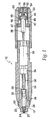
- a jet injector 10 comprises a nozzle assembly 12 attached to a housing 14.
- distal shall designate the end or direction toward the front of jet injector 10.
- proximal shall designate the end or direction toward the rear of the injector.
- longitudinal designates an axis connecting nozzle assembly 12 to jet injector 10
- transverse designates a direction substantially perpendicular to the longitudinal direction including arcs along the surface of jet injector 10, or nozzle assembly 12.
- Nozzle assembly 12 can be threadably connected to housing 14 such that it can be readily attached and detached.
- other known structures for mounting or attaching two components can be utilized as well to detachably mate nozzle assembly 12 to housing 14.
- injector 10 can be reused with various nozzle assemblies that may contain different medications of different doses either together or at different times.
- nozzle assembly 12 can be prefilled with medication and disposed of after each use.
- a medication filling device such as a coupling device can be used to fill the fluid chamber with medication.
- U.S. Patent No. 5,769,138 to Sadowski et al. the disclosure of which is herein incorporated by reference, is directed to such a coupling device.
- a trigger assembly 16 is located at the proximal end of housing 14. Trigger assembly 16 activates and triggers an energy source or force generating means 18 which forces medicament out of nozzle assembly 12.
- Energy source 18 can be a coil spring, a gas spring, or a gas propellant.
- nozzle assembly 12 has an injection assisting needle 20 movable within nozzle assembly 12. Needle 20 will be discussed in detail after first describing the other components of injector 10.
- the nozzle assembly 12 includes a nozzle member 22 having an opening 24 at the distal end, preferably having a diameter of about 0.04-0.4 inches or any other suitable diameter that would allow for the introduction of injection assisting needle 20 therein.
- Nozzle member 22 includes a cylindrical fluid chamber 26 terminating at the distal end in a right circular cone 28.
- Cone 28 can be a convex cone (as shown), a right circular cone, or any other suitable configuration.
- a plunger 30 having a pressure wall contoured to cone 28 is positioned to slide within fluid chamber 26.
- Plunger 30 can include sealing means such as one or more O-rings or the like (not shown) that are formed around its outer periphery to provide a seal, or the plunger itself can be a seal, as described in U.S. Patent No. 5,062,830 , the disclosure of which is incorporated herein by reference.
- the plunger can also include additional sealing means at spaced intervals to provide a better seal.
- Plunger 30 is connected to a ram 32 which in turn is connected to energy source 18.
- ram 32 can be integrally formed with an energy mechanism if desired.
- An inertia mass 34 is connected to or integrally formed with ram 32 near the end of ram 32 closest to plunger 30.
- Inertia mass 34 can be removably connected to ram 32 such that the mass can be adjusted to accommodate different types of injections, taking into consideration, for instance, the viscosity of the medication, the initial pressure build up desired, the strength of energy source 18, and the depth of injection penetration, etc.
- Inertia mass 34 cooperates with ram retainer 36 to limit the distance that ram 32 can travel toward nozzle assembly 12.
- One important safety aspect of this feature is that ram 32 cannot become a dangerous projectile if injector 10 is fired when nozzle assembly 12 is not present.
- Trigger assembly 16 includes a trigger extension 38 having a trigger engaging notch 5 40. Trigger extension 38 is attached to the end of ram 32, for example, by a threaded engagement. Trigger assembly 16 also comprises a latch housing sleeve 42 fixedly attached to an actuating mechanism 44. Actuating mechanism 44 is shown as a threaded coupling that operates by rotation movement. Latch housing sleeve 42 has a throughbore dimensioned to allow passage of trigger extension 38. Latch housing sleeve 42 further has a plurality of sidewall openings 46 dimensioned to allow passage of balls or ball bearings 48. A tubular button 50 having one open end and a closed end is telescopingly positioned with latch housing sleeve 42 as shown.
- Button 50 has a circumferential or annular groove 52 formed on an inner wall 54 thereof to allow portions of the balls 48 to engage groove 52 when trigger assembly 16 is in the fired position, i.e., not engaged with trigger extension 38 (not shown).
- Balls 48 are positioned so that they are substantially flush with an inner side wall surface 56 of latch housing sleeve 42 to allow trigger extension 38 to pass through latch housing sleeve 42.
- a latch ball retaining cup 58 is telescopingly positioned within button 50.
- a compression spring 60 is positioned between the cup 58 and button 50 to bias button 50 and cup 58 away from each other in the axial direction.
- Needle 20 has a plunger receptor 62 at the proximal end which is configured to accommodate plunger 30 as it slides within fluid chamber 26.
- plunger receptor 62 can be of any shape conforming to the exterior profile of plunger 30, it is preferably conical.
- a needle inner wall 64 is contoured to narrow like a funnel to a needle discharge channel 66 to accelerate the fluid as it is discharged.
- Needle discharge channel 66 extends to a discharge orifice 68 at the distal end of needle 20.
- Needle discharge orifice 68 has a diameter of 0.004 to 0.012 inches. Preferably, the diameter is 0.005 to 0.0075 inches.
- needle 20 can be of varied geometries such that it fits within fluid chamber 26 of nozzle assembly 12.
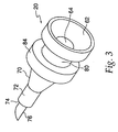
- needle 20 has a conical body section 70 which narrows gradually or tapers towards a cylindrical body section 72 of smaller circumference.
- a shoulder 74 is positioned to separate a needle tip 76 from cylindrical body section 72.
- Needle tip 76 is also cylindrical, but has a smaller circumference than cylindrical body section 72 such that needle tip 76 can fit within and extend through opening 24 of nozzle assembly 12.
- cylindrical body section 72 of needle. 20 has a circumference such that shoulder section 74, existing at the transition between cylindrical body section 72 and needle tip 76, prevents cylindrical body section 72 from existing within opening 24.
- needle tip 76 The length of needle tip 76 from its end to shoulder 74 is approximately 1 to 5 mm. Thus, needle tip 76 will penetrate the skin to a depth less than 5 mm. It should also be noted that although needle tip 76 is shown having a single beveled 5 end at a 45° angle, needle tip 76 can have any shape that penetrates the skin.
- needle 20 is positioned coaxially and retractably within the distal end of fluid chamber 26 such that when injector 10 is fired, needle tip 76 extends out opening 24 of nozzle assembly 12 at a speed sufficient to penetrate the outer layer of skin.
- needle tip 76 By inserting needle tip 76 to a depth less than 5 mm, typically only the epidermis of the skin is penetrated and the pressure needed to deliver the medicament to the desired region by jet injection is lower than that would otherwise be needed with needleless jet injection.
- the needle assisted jet injector delivers the medicament to a depth deeper than the length of the needle. This depth can include any region of the skin and beyond including intradermal, subcutaneous, and intramuscular.
- needle 20 includes a sealing means such as an O-ring 78 or the like formed around the outer periphery of needle 20 and accommodated by slot 80.
- a sealing means such as an O-ring 78 or the like formed around the outer periphery of needle 20 and accommodated by slot 80.
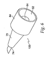
- needle 120 itself is the seal.
- slot 80 is not needed.
- Needle 120 also differs from needle 20 in that cylindrical body section 72 is absent so that conical body section 70 terminates at shoulder 74.
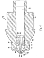
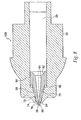
- FIG. 5 illustrates injection assisting needle 20 in its extended position. Needle tip 76 extends beyond the distal end of nozzle assembly 12. Shoulder 74 abuts the bored out inner section of nozzle opening 24 to prevent needle 20 from extending beyond needle tip 76.
- a retraction element 82 in this embodiment a spring, is compressed to provide a recoil force once the medicament is expelled so that needle tip 76 will retract back into nozzle opening 24.
- Needle 20 preferably has a ridge 84, the distal surface of which provides an annular area for the compression of retraction element 82.
- a washer can be used instead of the ridge 84 to contain O-ring 78 and compress the retracting mechanism during operation.
- FIGS. 7 and 8 show needle 120 of FIG. 6 with nozzle assembly 12 in which retraction element 82 is a resilient O-ring or other like material known to those skilled in the art.
- retraction element 82 is a resilient O-ring or other like material known to those skilled in the art.
- O-ring When an O-ring is used as retraction element 82, it can also act as a sealing mechanism, and for this reason the O-ring is preferred.
- the interior of needle 120 is similar to that of needle 20.
- FIG. 7 illustrates needle 120 in the retracted condition, before expelling medicament
- FIG. 8 shows the extended condition during which medicament is expelled. Similar to embodiments previously described, this embodiment functions to extend the needle tip 76 beyond nozzle opening 24 and penetrate the outer layer of the patient's skin during operation.
- needle 120 also preferably has ridge 84 around the proximal end to provide a surface which compresses the resilient material when the injector is triggered.
- FIGS. 9 and 10 Another embodiment of the present invention, shown in FIGS. 9 and 10 , uses a flexible member 86 as the retraction element.
- FIG. 9 illustrates the neutral condition before expelling the medicament.
- Flexible membrane 86 spans between walls 88 of nozzle assembly 12 which define fluid chamber 26 for holding medicament. Similar to embodiments previously described, the distal end of nozzle walls 88 act to conceal needle tip 76 until the injector is fired.
- Needle 220 is attached to flexible membrane 86 by any conventional means known to those skilled in the art. Preferably, needle 220 is integrally attached to flexible membrane 86 with an adhesive.
- FIG. 10 shows needle 220 in its extended position where the needle tip 76 extends beyond the end of walls 88 such that needle tip 76 penetrates the outer layer of skin to allow injection and deliver of the medicine at reduced pressure.
- a fixed needle i.e. a non-retracting needle that permanently extends beyond the nozzle assembly.
- Both a one-piece and a two-piece nozzle assembly with a fixed needle can be used and are contemplated by this invention.
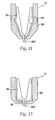
- FIGS. 11 and 12 show embodiments of the present invention with a two piece nozzle assembly with a fixed needle 320.
- a first section 90 of nozzle assembly 12 has needle 320 at the distal end and can either be attached internally or externally to a second section 92 to form nozzle assembly member 12.
- FIG. 11 shows a preferable friction-fitting or snapping attaching means 94 for both internal and external attachment of first section 90 and second section 92.
- FIG. 12 shows a preferable ultrasonic bonding means 96 of attachment. Although ultrasonic bonding features 96 can be placed at any location to attach the two pieces, preferably, the ultrasonic bonding features 96 are along the distal end at the interface between first and second sections 90, 92 to facilitate ease of manufacturing.
- FIG. 13 Another embodiment of a multi-piece nozzle assembly with fixed needle 320 is shown in FIG. 13 .
- the nozzle assembly consists of nozzle member 22 having an opening 24 designed to receive a tubular insert to create fixed needle 320.
- FIG. 13 shows a multi-piece nozzle assembly, fixed needle 320 can be made to be integral with nozzle assembly 12.
- FIG. 14a and FIG. 14b depict a preferred embodiment of the present invention having a retractable shield around the needle.
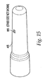
- An inner housing 25, shown in FIG. 16 snaps inside an outer housing 45, using a pair of snaps 65 located on the inner housing 25.
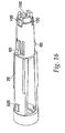
- the snaps 65 protrude through openings 85 in the outer housing 45, shown in FIG. 15 , and maintain the inner housing 25 and the outer housing 45 in a fixed relationship with one another.
- Other techniques known in the art, such as gluing and welding, could be used to hold the inner housing 25 and outer housing 45 together.
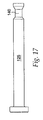
- the inner housing 25 has three trigger protrusions 100 extending from its distal end. These trigger protrusions 100 are shaped to mate with an annular recess 140 in ram 125 ( FIG. 17 ). Ram 125 is urged toward the distal end of the injector with a compression spring 240, however other energizing devices capable of producing an injection of up to 2 ml in about 2.5 seconds or less could be used. These energizing sources typically include rubber elastomers and compressed gas cartridges.
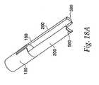
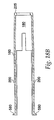
- a latch 160 shown in FIG. 18a , is slidable inside the outer housing 45 and surrounds the inner housing 25. The latch 160 has a barrel portion 180 at its distal end and a pair of extensions 200 at its proximal end.
- ridge 225 on the barrel portion 180 contacts the trigger protrusions 100 and maintains them in the annular recess 140 in ram 125, preventing the ram 125 from firing under the force of compression spring 240.
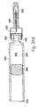
- a needle holder 260 mounts onto the inner housing 25 with right hand threads 280 and holds a cartridge assembly 300 inside the inner housing 25.
- the cartridge assembly 300 consists of a glass ampule 320 having an opening 340 in its proximal end and a seal 360 on its distal end.
- the glass ampule 320 typically holds between 0.02 and 2mL of a medicament 400.
- the ampule 320 can also be constructed of metal or other suitable materials known in the art.
- a rubber stopper 380 is slideable within the glass ampule 320 and seals the opening 340 in its proximal end of the glass ampule 320 so the medicament 400 stays inside the glass ampule 320.
- the seal 360 on the distal end comprises a rubber seal 420 formed on the end of the ampule 320 by conventional techniques, such as an aluminum cap 440 having a hole in its end.
- the ram 125 extends into the opening 340 in the proximal end of the glass ampule 320 and abuts the rubber stopper 380.
- at least a portion of the outer housing 45 is constructed of transparent or translucent material, so that the cartridge assembly 300 can be viewed by the user.
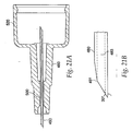
- a needle assembly 460 shown in FIG. 21 , consists of an injecting needle 480 glued inside a longitudinal pocket 500 in the needle hub 520. Grooves or other surface treatment on the longitudinal pocket 500 and on the injecting needle 480 enhance bonding between the injecting needle 480 and the needle hub 520. Alternatively, other known methods of fixing, such as molding, may be used to secure the injecting needle 480 to the needle hub 520.
- the injecting needle 480 is of 27 gauge, however other gauges may be suitable for different applications.
- the length of the needle 480 that extends beyond the distal end of the needle hub 520, and is used for injection, is preferably between 1 and 5 mm.
- the injecting needle 480 preferably has a 30° point. This angle decreases the length of the bevel 481 and thereby increases the effective length of the lumen 483. The increase in the effective length of the lumen 483 reduces the percentage of incomplete injections.
- Needle assembly 460 is mounted to the needle holder 260, and clockwise rotation of the needle holder 260 approximately one quarter of a turn threads it further into the inner housing 25 and forces the proximal end of the injecting needle 480 through rubber seal 420, thereby creating the drug path.
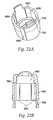
- a needle guard 540 depicted in FIG. 22a , is located at the distal end of the injecting device and conceals the injecting needle 480.
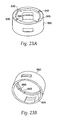
- the needle guard 540 snaps together with the needle guard cap 560, which is shown in FIGS. 23a and 23b .
- the needle guard cap 560 slides on extensions 200 of the latch 160, thereby allowing the needle guard 540 to slide longitudinally on the distal end of the injector to expose the injecting needle 480.
- Feet 580 at the end of extensions 200 prevent the needle guard cap 560 and consequently the needle guard 540 from sliding completely off the end of the device.
- Recesses 600 in the needle guard 540 and corresponding bosses 620 on the needle holder 260 translate any rotation of the needle guard 540 into rotation of the needle holder 260.
- Abutments 655 on the inner surface of the needle guard cap 560, shown in FIG. 23b are positioned relative to the feet 580 of the latch 160 to inhibit counter-clockwise rotation of the needle holder 260. This prevents the user from unscrewing the device and removing the cartridge assembly 300 from it.
- the needle guard cap has a inner flange 635 with a pair of cutouts 645 therein.
- the cutouts 645 correspond to the pair of bosses 625 on the inner housing 25.
- the flange 635 acts to prevent motion of the needle guard cap 560 and the needle guard 540 toward the proximal end of the device unless the cutouts 645 are rotated into alignment with the pair of bosses 625.
- This acts as a safety feature to prevent accidental firing of the injector.
- other known mechanisms such as a removable safety strip can be used to prevent accidental firing of the injector.
- a return spring 660 (not shown) rests on the needle holder 260 and urges the needle guard 540 toward the distal end of the injector, thereby keeping the injecting needle 480 concealed.
- a pair of stops 640 shown in FIG. 23 , extend from the needle guard cap 560 and are positioned relative to bosses 625 on the inner housing 25 such that the needle guard 540 and needle holder 260 cannot rotate clockwise under the force of return spring 660.
- Pressing the needle guard 540 toward the proximal end of the device causes the needle guard cap 560 to push the latch 160 longitudinally toward the proximal end of the device, thereby moving the ridge 225 on the barrel portion 180 of the latch 160 off the trigger protrusions 100 on the inner housing 25.
- This allows the trigger protrusions 100 to flex out of the annular recess 140 in the ram 125, thereby causing the ram 125 to fire under the force of compression spring 240.
- the ram 125 When the ram 125 fires, it slides rubber stopper 380 in the glass ampule 320 toward the distal end of the device, causing the medicament 400 to flow through the drug path (created by turning the needle holder 260 clockwise one quarter turn prior to firing, as discussed above) and eject from the injecting needle 480.
- needle guard 540 has a pocket 680 located therein.
- a locking ring 700 shown in FIG. 24 , sits in pocket 680 and prevents re-exposure of the injecting needle 480 after the device has been fired.
- Locking ring 700 has multiple splayed legs 720 at a first end and an undercut 740 at a second end that mates with extensions 760, which protrude from the needle holder 260.
- Locking ring 700 includes ramp portion 745 at the second end for engagement which similarly configured ramp portions 765 on extensions 760 of the needle holder 260. Ramp portions 745 and 765 provide for ease of mating between extensions 760 of the needle holder 260 and undercut 740 of the locking ring 700.
- extensions 760 engage the undercut 740 and become locked thereon.
- the locking ring 700 is pulled from pocket 680 in the needle guard 540 and splayed legs 720 expand radially outward.
- splayed legs 720 catch shoulder 780 on the needle guard 540 and restrict further movement of the needle guard 540, thereby preventing re-exposure of the injecting needle 480.
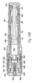
- Needle holder 260 includes extensions 760 with ramped portions 765 at a distal end and a cylindrical wall portion 761 at the proximal end.
- An inner wall 762 is provided between the distal and proximal ends of the needle holder and includes a circular opening 763 for receiving the needle assembly 520.
- Inner wall 762 is preferably arranged substantially perpendicular to cylindrical wall portion 761.
- Needle hub 520 seats fittingly inside the cylindrical wall portion 761 of the needle holder 260 and needle assembly 520 extends through opening 763 so that needle 480 extends out beyond extensions 760. Extensions 760 extend axially and distally outward from inner wall 762.
- Bosses 620 extend transversely outwardly from inner wall 762 in approximately the same plane as inner wall 762. Bosses 620 also extend transversely outwardly from cylindrical wall portion 761 such that bosses 620 are the outermost portions of needle holder 260.
- needle holder 260 has a length A of about 0.62 inches.
- Ramped portion 765 is preferably at an angle G of approximately 20°.
- the ramped portion is approximately 0.08 inches in length such that dimension B is approximately 0.539 inches.
- Extensions 760 include shoulder 764 for engaging undercut 740 of locking ring 700 such that dimension C is approximately 0.48 inches.
- Cylindrical wall portion 761 is preferably 0.32 inches in length D and is associated with inner wall 762 via an inner radiused curve K, having an approximate radius of 0.025 inches.
- Cylindrical wall portion 762 is associated with bosses 620 via an outer radiused curved portion J, having an approximate radius of 0.005 inches.
- Cylindrical wall portion 761 is preferably tapered outwardly such that the outer diameter opening H is greater than the inner diameter opening I.
- outer diameter opening H is approximately 0.39 inches and inner diameter opening is approximately 0.381 inches.
- circular opening 763 of inner wall 762 has a diameter E of approximately 0.17 inches and the distance F between extensions 760 is approximately 0.3 inches.
- the proximal end of locking ring 700 is shown as including undercut 740 and ramped portion 745.
- ramped portion 745 is preferably at an angle M of approximately 60° and is approximately 0.035 inches in length N.
- Undercut 740 is formed inwardly a distance O of approximately 0.05 inches relative to the proximal end of locking ring 700.
- Locking ring 700 is approximately 0.05 inches in thickness L and undercut 740 extends transversely a distance P of approximately 0.02 inches.
- Ramp 745 is configured and dimensioned for engaging ramped portion 765 of needle holder 260.
- FIGS. 32 and 33 While several dimensions are provided in FIGS. 32 and 33 for the proximal end of locking ring 700 and for the needle holder 260, they are purely exemplary in nature. It will be understood that other dimensions will also be useful and functional, the invention not being so limited in scope.
- the device also features a removable safety cap 800 that slides over the needle guard 540 and covers the device prior to its use.
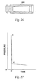
- the safety cap 800 includes a needle cap 820 ( FIG. 26 ) connected thereto, the needle cap 820 forming a sterile barrier around the needle assembly 460.
- the safety cap 800 has four longitudinal recesses 860 equally displaced about its inner surface 840. These longitudinal recesses 860 are dimensioned to accept two or more bosses 880 located at corresponding locations on the needle guard 540. Because of these two features, clockwise rotation of the safety cap 800 causes corresponding rotation of the needle guard 540 and the needle holder 260. Thus, the user may turn the safety cap 800 clockwise one quarter turn, prior to removing it from the device, to create the drug path and prepare the device for injection.
- the device of the preferred embodiment is operated by first turning the safety cap 800 clockwise one quarter of a turn, to create the drug path by inserting the proximal end of injecting needle 480 into the ampule 320. Rotating the safety cap 800 also aligns the cutaways 645 in the safety cap 560 with the bosses 625 on the inner housing 25, allowing the needle guard 540 to be depressed. Next the safety cap 800 and consequently the needle cap 820 are removed from the device.
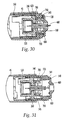
- FIGS. 28-31 the operation of the device is illustrated showing a series of positions for the injection process.
- the device is shown in the latched and ready to fire position, but prior to being pressed against a user's skin.
- the needle guard 540 is shown fully extended and needle 480 is retracted inside the needle guard 540.
- FIG. 29 the device is pressed against a user's skin and the needle guard 540 is partially retracted.
- the ramped portion 765 of the holder 260 and the ramp 745 of the locking ring 700 come into contact.
- the action of the two ramp portions sliding past one another generates a force greater than the return spring (not shown, but location referred to as location 660).
- the extensions 760 of the holder 260 are forced into the undercut 740 of locking ring 700.
- the force necessary to push the extensions 760 into under cut 740 is a threshold which must be overcome to fire the device.
- holder 260 will slide rapidly forward into the locking ring, causing the injector to fire.
- the injecting needle 480 enters the skin to a depth of between 1 and 5 mm.
- the movement of the needle guard 540 causes the ram 125 to fire and consequently between 0.02 and 2.0 ml of medicament 400 is forced out of the ampule 320 and through the drug path in under about 2.75 seconds.
- the needle 480 is fully extended such that it has entered the skin of a user and the injector has fired.
- the extensions 760 are forced into undercut 740.
- the engagement between extensions 760 and undercut 740 prevents holder 260 and locking ring 700 from separating.
- the needle guard 540 is shown after being removed from the injection site. Once the device is removed from the injection site, the needle guard 540 returns to its original position under the force of return spring 660, concealing the injecting needle 480.
- the legs 720 of locking ring 700 are withdrawn from the pocket 680 in needle guard 540 and are extended or sprung outwardly. In this position, legs 720 engage shoulder 780 of needle guard 540 if a user attempts to reuse the needle 480, thereby preventing reuse. In this way, the locking ring 700 locks the needle guard 540 in place to prevent re-exposure of the injecting needle 480.
- a push button could be located at the proximal end of the device and be locked in an idle position. The movement of the needle guard 540 could unlock the push button and allow the user to depress it and consequently fire the device.
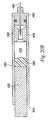
- FIG. 20b shows another embodiment of the cartridge assembly 302 of the preferred embodiment.
- the cartridge assembly 302 comprises a glass ampule 322 and a needle assembly 462 sealed on its distal end.
- a pierceable seal 422 is located in proximity to the proximal end of the injecting needle 482 and creates a barrier between the medicament 402 and the injecting needle 482.
- a rubber stopper 382 is slideable within the glass ampule 322 and seals an opening 342 in its proximal end so the medicament 402 stays inside the glass ampule 322.
- the ram 125 urges the rubber stopper 382 toward the distal end of the injector.
- the pierceable seal 422 is forced onto the distal end of the injecting needle 482, thereby breaking the barrier and creating the drug path.
- this cartridge assembly 302 no turning of the device is required to create the drug path, and the threads on the inner housing 25 and on the needle holder 260 can be replaced by known permanent fixing techniques, such as gluing or welding.
- FIG. 27 shows a pressure-time curve for a jet injector.
- the peak pressure at point c is the pressure needed to penetrate the skin and point d and beyond is the pressure at which a jet stream of medicament is delivered.
- needle assisted jet injectors do not need to achieve as high as peak pressure as conventional jet injectors because the outer layer of skin is penetrated by the needle.
- the needle assisted injector according to the present invention can be operated using a lower generating energy source and still maintain the quality of the injection. Specifically, experimentation has shown that a higher percentage of successful injections can be achieved with a needle assisted jet injector having a needle that penetrates the skin to a depth of 1 mm and 20 lb. force generating means as with a conventional needleless jet injectors having 55 lb. force generating means. Similar results have been achieved with needles that penetrate 1-3 mm and force generating sources providing 20 lbs. and 40 lbs. of force.
- Another advantage of the needle assisted jet injector according to the present invention is the decreased injection time compared to syringes or auto-injectors.
- the quality of the injection can be compromised due to any number of factors.
- the patient could move the syringe or auto-injector prior to completion of the injection. Such movement could occur either accidently or intentionally because of injection-related pain.
- the needle assisted jet injector like other jet injectors, can have an injection time of less than 1 second. The short injection time minimizes the possibility of compromising the quality of the injection.
Landscapes
- Health & Medical Sciences (AREA)
- Engineering & Computer Science (AREA)
- Public Health (AREA)
- Veterinary Medicine (AREA)
- Biomedical Technology (AREA)
- Heart & Thoracic Surgery (AREA)
- Hematology (AREA)
- Life Sciences & Earth Sciences (AREA)
- Animal Behavior & Ethology (AREA)
- General Health & Medical Sciences (AREA)
- Vascular Medicine (AREA)
- Anesthesiology (AREA)
- Environmental & Geological Engineering (AREA)
- Infusion, Injection, And Reservoir Apparatuses (AREA)
- Nozzles (AREA)
- Catching Or Destruction (AREA)
- Cleaning By Liquid Or Steam (AREA)
- Perforating, Stamping-Out Or Severing By Means Other Than Cutting (AREA)
- Massaging Devices (AREA)
- Surgical Instruments (AREA)
Claims (11)
- Mécanisme de blocage pour utilisation avec un injecteur a jet assisté d'une aiguille, l'injecteur a jet assisté d'une aiguille a un assemblage d'aiguille avec une aiguille et une protection d'aiguille (540) associées avec l'assemblage de l'aiguille, ladite protection de l'aiguille est configurée pour placement contre une surface pour être injectée et pour protéger l'aiguille avant et après une injection de l'injecteur, la protection de l'aiguille est mobile entre une première position rétractée, où l'aiguille est rétractée à l'intérieur de la protection de l'aiguille, une position étendue où l'aiguille s'étend à l'extérieur de la protection de l'aiguille pour injection dans la surface, et une seconde position retractée, où l'aiguille est retractée à l'intérieur de la protection de l'aiguille après injection, ledit mécanisme de blocage comprenant:un membre de support (260) configuré et dimensionné pour tenir l'assemblage de l'aiguille et ayant au moins une première portion embrayante (760); etun membre de blocage (700) associé operationellement avec la protection de l'aiguille (540) et le membre de support (260), ledit membre de blocage (700) ayant au moins une seconde portion embrayante dans la position étendue et la seconde position retractée,où le membre de blocage (700) est associé avec la protection de l'aiguille (540) dans la première position retractée, est associé avec le membre de support et les seconde positions retractées, et est en relation de blocage avec la protection de l'aiguille dans la seconde position retractée afin de pouvoir bloquer du mouvement supplémentaire de la protection de l'aguille jusqu'à la position étendue et de dissuader réutilisation de l'aiguille.
- Mécanisme de blocage selon la revendication 1, où le membre de blocage (700) comprend:une portion substantiellement annulaire;au moins un pied biaisé à l'extérieur (720) s'étendant d'une extrémité distale de ladite portion annulaire; etla protection de l'aiguille (540) comprend au moins une poche (680) pour accepter le au moins un pied quand le membre de blocage est associé avec la protection de l'aiguille dans la première position retractée,où le pied (720) maintient sa position en association avec la protection de l'aiguille (540) due à sa force biaisée à l'extérieure, ledit pied est résilient afin d'être détachable du au moins une poche de protection de l'aiguille après l'application de la force sufficiente pour surmonter la force biaisée à l'extérieure dudit pied.
- Mécanisme de blocage selon la revendication 2, où la au moins une seconde portion embrayante du membre de blocage (700) est une portion contre-dépouille (740) formée à une extrémité proximale de la portion annulaire, ladite portion contre-dépouille est dimensionnée et configurée pour accepter la premiere portion embrayante (760) du membre de support (260) pour accoupler avec ceci.
- Mécanisme de blocage selon la revendication 3, où l'extrémité proximale de la portion annulaire du membre de blocage (700) de plus comprend une portion inclinée (745) sur une surface intérieure s'étendant à l'intérieur de l'extrêmité de ceci, ladite portion inclinée du membre de blocage est relativement angulaire par rapport à une surface extérieure circumferentielle de la portion annulaire pour embrayage avec la premiere portion embrayante (760) du membre de support (260) avant le membre du support embraie la contre-dépouille (740).
- Mécanisme de blocage selon la revendication 2, où le au moins un pied biaisé à l'extérieur (720) saute à l'extérieur après débrayage avec la au moins une poche de protection d'aiguille (680) et est contigu à un épaulement (780) formé sur une surface intérieure de la protection de l'aiguille (540) dans la seconde position retractée pour prévenir réutilisation de l'aiguille à l'aide de blocage substantiellement proximale de mouvement de la protection de l' aiguille (540).
- Mécanisme de blocage selon la revendication 1, où le membre de support (260) comprend:une portion substantiellement cylindrique (761) à une extrêmité proximale de celle-ci;la au moins première portion embrayante (760) à une extrémité distale de celle-ci; etet un mur intérieur (762) positionné substantiellement entre elles, ladite portion (761) cylindrique (761) et mur intérieure (762) sont configurés et dimensionés pour accoupler avec l'assemblage de l'aiguille.
- Mécanisme de blocage selon la revendication 6, où le mur intérieur (762) comprend une ouverture circulaire (763) s'étendant entre les côtés proximals et distals de celle-ci pour recevoir une portion de l'assemblage de l'aiguille à travers celle-ci.
- Mécanisme de blocage selon la revendication 6, où la première portion embrayante (760) est au moins un bras s'étendant de manière distale du mur intérieur (762), ledit bras y compris une portion d'extension configurée et dimensionée pour l'assise dans la seconde portion embrayante du membre de blocage (700).
- Membre de blocage selon la revendication 8, où la portion d'extension du bras de ladite première portion embrayante comprend une portion inclinée (765) pour association avec le membre de blocage (700).
- Mécanisme de blocage selon la revendication 4, où le membre de support (260) comprend:une portion substantiellement cylindrique (761) à une extrémité proximale de celle-ci;la au moins première portion embrayante (760) à une extrémité distale de celle-ci; etet un mur intérieur positionné substantiellement entre elles, ladite portion cylindrique et mur intérieur sont configurés et dimensionés pour accoupler avec l'assemblage de l'aiguille,où la premiere portion embrayante (760) est au moins un bras s'étendant de manière distale du mur intérieur, ledit bras y compris une portion d'extension configurée et dimensionnée pour l'assise dans la seconde portion embrayante du membre de blocage, ladite portion d'extension du bras y compris une portion inclinée pour association avec la portion inclinée du membre de blocage.
- Mécanisme de blocage selon la revendication 10, où la portion inclinée (765) du membre de support (260) est complémentaire de la portion inclinée (745) du membre de blocage (700) ainsi que les deux portions inclinées permettent à d'autres portions inclinées de glisser au-dessus permettant à la premiere portion embrayante d'embrayer la seconde portion embrayante dans la position étendue.
Applications Claiming Priority (3)
| Application Number | Priority Date | Filing Date | Title |
|---|---|---|---|
| US09/425,965 US6391003B1 (en) | 1999-10-25 | 1999-10-25 | Locking mechanism for a jet injector |
| US425965 | 1999-10-25 | ||
| PCT/US2000/029000 WO2001032255A1 (fr) | 1999-10-25 | 2000-10-20 | Mecanisme de blocage pour injecteur a jet |
Publications (3)
| Publication Number | Publication Date |
|---|---|
| EP1225952A1 EP1225952A1 (fr) | 2002-07-31 |
| EP1225952A4 EP1225952A4 (fr) | 2009-04-01 |
| EP1225952B1 true EP1225952B1 (fr) | 2010-02-24 |
Family
ID=23688751
Family Applications (1)
| Application Number | Title | Priority Date | Filing Date |
|---|---|---|---|
| EP00978256A Expired - Lifetime EP1225952B1 (fr) | 1999-10-25 | 2000-10-20 | Mecanisme de blocage pour injecteur a jet |
Country Status (8)
| Country | Link |
|---|---|
| US (1) | US6391003B1 (fr) |
| EP (1) | EP1225952B1 (fr) |
| JP (1) | JP4236843B2 (fr) |
| CN (1) | CN1382064A (fr) |
| AT (1) | ATE458516T1 (fr) |
| AU (1) | AU1573501A (fr) |
| DE (1) | DE60043894D1 (fr) |
| WO (1) | WO2001032255A1 (fr) |
Cited By (1)
| Publication number | Priority date | Publication date | Assignee | Title |
|---|---|---|---|---|
| DE10066400B4 (de) * | 2000-03-01 | 2012-01-19 | Tecpharma Licensing Ag | System aus Injektor-Kanülenträger und Schieberhülse |
Families Citing this family (98)
| Publication number | Priority date | Publication date | Assignee | Title |
|---|---|---|---|---|
| GB9716065D0 (en) * | 1997-07-31 | 1997-10-01 | Owen Mumford Ltd | Improvements relating to injection devices |
| DE10009814B4 (de) | 2000-03-01 | 2008-03-06 | Tecpharma Licensing Ag | Einweg-Injektorkappe |
| CN1419458A (zh) * | 2000-03-23 | 2003-05-21 | 安塔雷斯制药公司 | 单独使用的一次性喷射式注射器 |
| ATE300968T1 (de) * | 2000-05-31 | 2005-08-15 | Novo Nordisk As | Wegwerfbare doppelspritzeninjektionsnadel |
| US6547764B2 (en) * | 2000-05-31 | 2003-04-15 | Novo Nordisk A/S | Double pointed injection needle |
| ES2605353T3 (es) | 2000-08-02 | 2017-03-14 | Becton, Dickinson And Company | Sistema de aguja de pluma y pantalla protectora de seguridad |
| US7235063B2 (en) * | 2001-08-21 | 2007-06-26 | D'antonio Consultants International, Inc. | Hypodermic injection system |
| US6796967B2 (en) * | 2001-10-22 | 2004-09-28 | Nps Pharmaceuticals, Inc. | Injection needle assembly |
| GB0125506D0 (en) * | 2001-10-24 | 2001-12-12 | Weston Medical Ltd | Needle free injection method and apparatus |
| CN1294997C (zh) * | 2001-11-30 | 2007-01-17 | 诺沃挪第克公司 | 安全针组件 |
| JP3993169B2 (ja) | 2002-02-11 | 2007-10-17 | アンタレス・ファーマ・インコーポレーテッド | 皮内注射器 |
| US7252651B2 (en) * | 2003-01-07 | 2007-08-07 | Becton, Dickinson And Company | Disposable injection device |
| US8932264B2 (en) * | 2003-08-11 | 2015-01-13 | Becton, Dickinson And Company | Medication delivery pen assembly with needle locking safety shield |
| GB2414406B (en) | 2004-05-28 | 2009-03-18 | Cilag Ag Int | Injection device |
| GB2414775B (en) * | 2004-05-28 | 2008-05-21 | Cilag Ag Int | Releasable coupling and injection device |
| GB2414409B (en) * | 2004-05-28 | 2009-11-18 | Cilag Ag Int | Injection device |
| GB2414404B (en) | 2004-05-28 | 2009-06-03 | Cilag Ag Int | Injection device |
| GB2414400B (en) | 2004-05-28 | 2009-01-14 | Cilag Ag Int | Injection device |
| GB2414399B (en) * | 2004-05-28 | 2008-12-31 | Cilag Ag Int | Injection device |
| GB2414405B (en) * | 2004-05-28 | 2009-01-14 | Cilag Ag Int | Injection device |
| GB2414401B (en) | 2004-05-28 | 2009-06-17 | Cilag Ag Int | Injection device |
| GB2414402B (en) * | 2004-05-28 | 2009-04-22 | Cilag Ag Int | Injection device |
| GB2414403B (en) * | 2004-05-28 | 2009-01-07 | Cilag Ag Int | Injection device |
| US8048035B2 (en) * | 2004-08-06 | 2011-11-01 | Meridian Medical Technologies, Inc. | Automatic injector with needle cover |
| US7449012B2 (en) * | 2004-08-06 | 2008-11-11 | Meridian Medical Technologies, Inc. | Automatic injector |
| FI1850892T4 (fi) * | 2005-01-24 | 2023-08-31 | Neula-avusteinen esitäytetyn ruiskun omaava suihkuinjektori | |
| GB2424835B (en) * | 2005-04-06 | 2010-06-09 | Cilag Ag Int | Injection device (modified trigger) |
| GB2424836B (en) | 2005-04-06 | 2010-09-22 | Cilag Ag Int | Injection device (bayonet cap removal) |
| GB2425062B (en) * | 2005-04-06 | 2010-07-21 | Cilag Ag Int | Injection device |
| GB2424838B (en) * | 2005-04-06 | 2011-02-23 | Cilag Ag Int | Injection device (adaptable drive) |
| GB2427826B (en) | 2005-04-06 | 2010-08-25 | Cilag Ag Int | Injection device comprising a locking mechanism associated with integrally formed biasing means |
| ATE452670T1 (de) | 2005-08-30 | 2010-01-15 | Cilag Gmbh Int | Nadelvorrichtung für eine vorgefüllte spritze |
| US20110098656A1 (en) | 2005-09-27 | 2011-04-28 | Burnell Rosie L | Auto-injection device with needle protecting cap having outer and inner sleeves |
| WO2007065339A1 (fr) * | 2005-12-05 | 2007-06-14 | Zhongshan Botai Pharmaceutic Instruments Co., Ltd. | Seringue automatique |
| WO2007131013A1 (fr) | 2006-05-03 | 2007-11-15 | Antares Pharma, Inc. | Injecteur de reconstitution à deux étages |
| US9144648B2 (en) * | 2006-05-03 | 2015-09-29 | Antares Pharma, Inc. | Injector with adjustable dosing |
| GB2438593B (en) | 2006-06-01 | 2011-03-30 | Cilag Gmbh Int | Injection device (cap removal feature) |
| GB2438590B (en) | 2006-06-01 | 2011-02-09 | Cilag Gmbh Int | Injection device |
| GB2438591B (en) | 2006-06-01 | 2011-07-13 | Cilag Gmbh Int | Injection device |
| US8251951B2 (en) * | 2006-12-13 | 2012-08-28 | Suzuken Company Limited | Injection needle cartridge and injector |
| US7871397B2 (en) | 2006-12-26 | 2011-01-18 | Stat Medical Devices, Inc. | Pen needle tip |
| US7540858B2 (en) * | 2007-01-23 | 2009-06-02 | Becton, Dickinson And Company | Retracting safety pen needle |
| DE102007008369A1 (de) * | 2007-02-16 | 2008-08-21 | Lts Lohmann Therapie-Systeme Ag | Einweginjektor mit mindestens einem zentralen Zugstab |
| US8128605B2 (en) * | 2007-12-24 | 2012-03-06 | Mentor Worldwide Llc | Syringe for use in medical applications |
| EP2268342B1 (fr) | 2008-03-10 | 2015-09-16 | Antares Pharma, Inc. | Dispositif de sécurité pour injecteur |
| GB2461086B (en) | 2008-06-19 | 2012-12-05 | Cilag Gmbh Int | Injection device |
| GB2461084B (en) | 2008-06-19 | 2012-09-26 | Cilag Gmbh Int | Fluid transfer assembly |
| GB2461085B (en) | 2008-06-19 | 2012-08-29 | Cilag Gmbh Int | Injection device |
| GB2461089B (en) | 2008-06-19 | 2012-09-19 | Cilag Gmbh Int | Injection device |
| GB2461087B (en) | 2008-06-19 | 2012-09-26 | Cilag Gmbh Int | Injection device |
| EP3581224A1 (fr) | 2008-08-05 | 2019-12-18 | Antares Pharma, Inc. | Injecteur à dosage multiple |
| JP5732039B2 (ja) | 2009-03-20 | 2015-06-10 | アンタレス・ファーマ・インコーポレーテッド | 危険有害性薬剤の注入システム |
| US20110023281A1 (en) * | 2009-04-30 | 2011-02-03 | Stat Medical Devices, Inc. | Pen injection device cap with integral pen needle quick release and/or removal system |
| US9700681B2 (en) * | 2009-05-15 | 2017-07-11 | Stat Medical Devices, Inc. | Pen needle with quick release and/or removal system |
| US20110026930A1 (en) * | 2009-07-29 | 2011-02-03 | Zhi Cui | Methods and apparatus to upgrade communication services in subscriber distribution areas |
| US20110060292A1 (en) * | 2009-08-14 | 2011-03-10 | Stat Medical Devices, Inc. | Pen needle storage device with integral removal and/or installation system |
| WO2012026100A1 (fr) * | 2010-08-23 | 2012-03-01 | Nanbu Plastics Co., Ltd. | Dispositif d'administration de médicament par voie percutanée et formation d'aiguille utilisée pour le dispositif |
| JP5631128B2 (ja) * | 2010-09-07 | 2014-11-26 | 株式会社トクヤマデンタル | ノック式吐出容器 |
| US10463803B2 (en) | 2010-11-12 | 2019-11-05 | Stat Medical Devices, Inc. | Pen needle with quick release and/or removal system |
| US8961470B2 (en) | 2011-02-17 | 2015-02-24 | Steven Schraga | Pen needle with safety shield system |
| US20140042741A1 (en) * | 2011-04-28 | 2014-02-13 | Ilona Eggert | Dispense interface with lockout element |
| CN103608061B (zh) * | 2011-04-28 | 2016-01-20 | 赛诺菲-安万特德国有限公司 | 用于分配接口的锁定元件 |
| WO2012161685A1 (fr) * | 2011-05-23 | 2012-11-29 | Boehringer Ingelheim International Gmbh | Nébuliseur |
| DE102011107199A1 (de) * | 2011-07-13 | 2013-01-17 | Haselmeier Gmbh | Injektionsgerät und Verfahren zu dessen Herstellung |
| US9220660B2 (en) | 2011-07-15 | 2015-12-29 | Antares Pharma, Inc. | Liquid-transfer adapter beveled spike |
| US8496619B2 (en) | 2011-07-15 | 2013-07-30 | Antares Pharma, Inc. | Injection device with cammed ram assembly |
| DK3400982T3 (da) * | 2011-07-19 | 2021-09-13 | Sanofi Aventis Deutschland | Patronholder til en lægemiddeladministrationsanordning |
| EP2572744A1 (fr) * | 2011-09-23 | 2013-03-27 | Sanofi-Aventis Deutschland GmbH | Dispositif de sécurité d'aiguille |
| EP2578258A1 (fr) * | 2011-10-06 | 2013-04-10 | Sanofi-Aventis Deutschland GmbH | Dispositif de sécurité d'aiguille |
| US9078978B2 (en) | 2011-12-28 | 2015-07-14 | Stat Medical Devices, Inc. | Needle assembly with safety system for a syringe or fluid sampling device and method of making and using the same |
| DK2822618T3 (da) | 2012-03-06 | 2024-01-22 | Antares Pharma Inc | Forfyldt nål med brudkraftfunktion |
| AU2013203784A1 (en) | 2012-04-06 | 2013-10-24 | Kaushik J. Dave | Needle assisted jet injection administration of testosterone compositions |
| US9364610B2 (en) | 2012-05-07 | 2016-06-14 | Antares Pharma, Inc. | Injection device with cammed ram assembly |
| WO2014124464A1 (fr) | 2013-02-11 | 2014-08-14 | Travanty Michael | Dispositif d'injection à jet assistée par aiguille ayant une force de déclenchement réduite |
| US9707354B2 (en) | 2013-03-11 | 2017-07-18 | Antares Pharma, Inc. | Multiple dosage injector with rack and pinion dosage system |
| WO2014165136A1 (fr) | 2013-03-12 | 2014-10-09 | Antares Pharma, Inc. | Seringues pré-remplies à volume constant et leurs trousses |
| JP6211790B2 (ja) | 2013-04-23 | 2017-10-11 | 大成化工株式会社 | 注射器 |
| GB2517896B (en) | 2013-06-11 | 2015-07-08 | Cilag Gmbh Int | Injection device |
| GB2515038A (en) | 2013-06-11 | 2014-12-17 | Cilag Gmbh Int | Injection device |
| GB2515039B (en) | 2013-06-11 | 2015-05-27 | Cilag Gmbh Int | Injection Device |
| GB2515032A (en) | 2013-06-11 | 2014-12-17 | Cilag Gmbh Int | Guide for an injection device |
| WO2015054213A1 (fr) | 2013-10-07 | 2015-04-16 | Wotton Paul K | Modulation d'hématocrites par injection de testostérone par jet à l'aide d'une aiguille |
| CA2939791C (fr) | 2014-02-19 | 2021-06-15 | Hermanus L. Jooste | Administration de compositions de testosterone par injection par jet assistee par aiguille |
| US10118000B2 (en) | 2014-04-21 | 2018-11-06 | Stat Medical Devices, Inc. | Pen needle installation and removal safety cover and pen needle assembly utilizing the same |
| US10155091B2 (en) | 2014-07-11 | 2018-12-18 | Stat Medical Devices, Inc. | Pen needle tip and method of making and using the same |
| JP2017523858A (ja) | 2014-08-10 | 2017-08-24 | アンタレス・ファーマ・インコーポレーテッド | 注射装置で使用するためのシリンジ緩衝器 |
| BR112017011213A2 (pt) | 2014-12-23 | 2018-02-14 | Automed Pty Ltd | aparelho de fornecimento, sistema e métodos associados |
| US10251964B2 (en) | 2016-08-23 | 2019-04-09 | Drma Group International Llc | Self-disinfecting needleless device |
| US10195110B2 (en) | 2016-09-08 | 2019-02-05 | Drma Group International Llc | Capping device for disinfecting medical container |
| US10391294B2 (en) | 2016-09-12 | 2019-08-27 | Drma Group International Llc | Disinfecting cap |
| US10610676B2 (en) | 2016-09-26 | 2020-04-07 | Drma Group International Llc | Disinfecting luer connector |
| US10182968B2 (en) | 2017-03-06 | 2019-01-22 | Drma Group International Llc | Disinfecting capping device for sharp medical objects |
| US11541219B2 (en) | 2017-07-10 | 2023-01-03 | Drma Group International Llc | Capping device for disinfecting medical injection membranes |
| CN111989129A (zh) * | 2018-04-01 | 2020-11-24 | 诺和诺德股份有限公司 | 具有记忆元件的自动注射装置 |
| US11850401B2 (en) | 2018-06-08 | 2023-12-26 | Antares Pharma, Inc. | Auto-insert injector |
| AU2020348532A1 (en) * | 2019-09-17 | 2022-03-31 | Becton Dickinson Holdings Pte. Ltd. | A passive safety device, an injection device comprising the same, and a method for manufacturing said injection device |
| CN110882447A (zh) * | 2019-11-11 | 2020-03-17 | 徐州深丰精密机械有限公司 | 一种医疗用注射器组件 |
| US11957542B2 (en) | 2020-04-30 | 2024-04-16 | Automed Patent Holdco, Llc | Sensing complete injection for animal injection device |
Family Cites Families (37)
| Publication number | Priority date | Publication date | Assignee | Title |
|---|---|---|---|---|
| DE1957833A1 (de) | 1968-11-21 | 1970-07-02 | Maurice Steiner | Injektionsspritze,insbesondere von dem Patienten selbst gehandhabte Injektionsspritze |
| US3605744A (en) | 1969-04-22 | 1971-09-20 | Edward M Dwyer | Injection apparatus and method of injecting |
| US3797491A (en) | 1971-02-11 | 1974-03-19 | Ampoules Inc | Method of performing an intramuscular injection |
| BE795162A (fr) | 1972-02-10 | 1973-08-08 | Philips Nv | Injektie-inrichting |
| FR2237643B1 (fr) | 1973-07-17 | 1978-03-17 | Steiner Maurice | |
| SE7502318L (sv) | 1975-03-03 | 1976-09-06 | Af Ekenstam Thuresson Bo | Emballage for flytande till halvfasta material, passande for smerre kvantiteter |
| US4127118B1 (en) | 1977-03-16 | 1995-12-19 | Alvaro Latorre | Method of effecting and enhancing an erection |
| US4227528A (en) | 1978-12-26 | 1980-10-14 | Wardlaw Stephen C | Automatic disposable hypodermic syringe |
| US4258713A (en) | 1979-07-23 | 1981-03-31 | Wardlaw Stephen C | Automatic disposable hypodermic syringe |
| US4378015A (en) | 1981-12-21 | 1983-03-29 | Wardlaw Stephen C | Automatic injecting syringe |
| FR2539302B1 (fr) | 1983-01-17 | 1986-03-14 | Brunet Jean Louis | Seringue a usage medical |
| US4719825A (en) | 1986-03-24 | 1988-01-19 | Lahaye Peter G | Metering needle assembly |
| US5569190A (en) | 1987-06-08 | 1996-10-29 | D'antonio; Nicholas F. | Hypodermic fluid dispenser |
| US5080648A (en) | 1987-06-08 | 1992-01-14 | Antonio Nicholas F D | Hypodermic fluid dispenser |
| US6056716A (en) | 1987-06-08 | 2000-05-02 | D'antonio Consultants International Inc. | Hypodermic fluid dispenser |
| US4790824A (en) | 1987-06-19 | 1988-12-13 | Bioject, Inc. | Non-invasive hypodermic injection device |
| IT1227658B (it) * | 1988-12-01 | 1991-04-23 | Vittorio Boschetti B | Siringa monouso con rientro e blocco dell'ago a fine iniezione a scopo di evitare il reimpiego |
| US5062830A (en) | 1990-04-04 | 1991-11-05 | Derata Corporation | Dry disposable nozzle assembly for medical jet injector |
| US5505694A (en) | 1990-08-22 | 1996-04-09 | Tcnl Technologies, Inc. | Apparatus and method for raising a skin wheal |
| GB9100819D0 (en) | 1991-01-15 | 1991-02-27 | Medimech Int Ltd | Subcutaneous injector |
| US5176643A (en) | 1991-04-29 | 1993-01-05 | George C. Kramer | System and method for rapid vascular drug delivery |
| GB9111049D0 (en) | 1991-05-22 | 1991-07-17 | Parkin Adrian | Hypodermic needle |
| US5267962A (en) * | 1992-06-10 | 1993-12-07 | Jenson Robert W | Disposable hypodermic syringe with needle safe feature |
| US5304128A (en) | 1992-09-22 | 1994-04-19 | Habley Medical Technology Corporation | Gas powered self contained syringe |
| GB9408500D0 (en) | 1994-04-28 | 1994-06-22 | Pa Consulting Services | Improvements in or relating to injection devices |
| US5637094A (en) | 1994-11-04 | 1997-06-10 | Pos-T-Vac, Inc. | Multiple dosage syringe |
| US5599302A (en) | 1995-01-09 | 1997-02-04 | Medi-Ject Corporation | Medical injection system and method, gas spring thereof and launching device using gas spring |
| US5562625A (en) * | 1995-05-02 | 1996-10-08 | Stefancin, Jr.; Ronald J. | Reusasble syringe with a disposable needle sheath |
| US5562626A (en) * | 1995-09-11 | 1996-10-08 | Sanpietro; Joseph A. | Safety syringe |
| US5658259A (en) | 1995-10-19 | 1997-08-19 | Meridian Medical Technologies, Inc. | Dental cartridge assembly auto-injector with protective needle cover |
| ZA9610374B (en) | 1995-12-11 | 1997-06-23 | Elan Med Tech | Cartridge-based drug delivery device |
| US5769138A (en) | 1996-04-01 | 1998-06-23 | Medi-Ject Corporation | Nozzle and adapter for loading medicament into an injector |
| GB9612724D0 (en) | 1996-06-18 | 1996-08-21 | Owen Mumford Ltd | Improvements relating to injection devices |
| JPH1129958A (ja) | 1997-07-11 | 1999-02-02 | Komatsu Ltd | 建設機械 |
| EP0996477B1 (fr) | 1997-07-14 | 2004-01-14 | Novo Nordisk A/S | Element d'injection |
| IE970782A1 (en) | 1997-10-22 | 1999-05-05 | Elan Corp | An improved automatic syringe |
| US6428528B2 (en) * | 1998-08-11 | 2002-08-06 | Antares Pharma, Inc. | Needle assisted jet injector |
-
1999
- 1999-10-25 US US09/425,965 patent/US6391003B1/en not_active Expired - Lifetime
-
2000
- 2000-10-20 AT AT00978256T patent/ATE458516T1/de not_active IP Right Cessation
- 2000-10-20 AU AU15735/01A patent/AU1573501A/en not_active Abandoned
- 2000-10-20 EP EP00978256A patent/EP1225952B1/fr not_active Expired - Lifetime
- 2000-10-20 DE DE60043894T patent/DE60043894D1/de not_active Expired - Lifetime
- 2000-10-20 CN CN00814839A patent/CN1382064A/zh active Pending
- 2000-10-20 WO PCT/US2000/029000 patent/WO2001032255A1/fr active Application Filing
- 2000-10-20 JP JP2001534458A patent/JP4236843B2/ja not_active Expired - Lifetime
Cited By (1)
| Publication number | Priority date | Publication date | Assignee | Title |
|---|---|---|---|---|
| DE10066400B4 (de) * | 2000-03-01 | 2012-01-19 | Tecpharma Licensing Ag | System aus Injektor-Kanülenträger und Schieberhülse |
Also Published As
| Publication number | Publication date |
|---|---|
| JP4236843B2 (ja) | 2009-03-11 |
| ATE458516T1 (de) | 2010-03-15 |
| DE60043894D1 (de) | 2010-04-08 |
| US6391003B1 (en) | 2002-05-21 |
| JP2003512904A (ja) | 2003-04-08 |
| WO2001032255A1 (fr) | 2001-05-10 |
| EP1225952A4 (fr) | 2009-04-01 |
| AU1573501A (en) | 2001-05-14 |
| CN1382064A (zh) | 2002-11-27 |
| EP1225952A1 (fr) | 2002-07-31 |
Similar Documents
| Publication | Publication Date | Title |
|---|---|---|
| EP1225952B1 (fr) | Mecanisme de blocage pour injecteur a jet | |
| EP1336419B1 (fr) | Injecteur à jet associé à une aiguille | |
| US10646662B2 (en) | Intradermal injector | |
| EP1102606B1 (fr) | Sonde d'aide a l'injection pour ensemble injecteur medical | |
| US6123684A (en) | Loading mechanism for medical injector assembly | |
| EP2268342B1 (fr) | Dispositif de sécurité pour injecteur |
Legal Events
| Date | Code | Title | Description |
|---|---|---|---|
| PUAI | Public reference made under article 153(3) epc to a published international application that has entered the european phase |
Free format text: ORIGINAL CODE: 0009012 |
|
| 17P | Request for examination filed |
Effective date: 20020419 |
|
| AK | Designated contracting states |
Kind code of ref document: A1 Designated state(s): AT BE CH CY DE DK ES FI FR GB GR IE IT LI LU MC NL PT SE |
|
| AX | Request for extension of the european patent |
Free format text: AL PAYMENT 20020419;LT PAYMENT 20020419;LV PAYMENT 20020419;MK PAYMENT 20020419;RO PAYMENT 20020419;SI PAYMENT 20020419 |
|
| RIC1 | Information provided on ipc code assigned before grant |
Free format text: 7A 61M 5/30 A |
|
| RAP1 | Party data changed (applicant data changed or rights of an application transferred) |
Owner name: ANTARES PHARMA, INC. |
|
| A4 | Supplementary search report drawn up and despatched |
Effective date: 20090227 |
|
| RIC1 | Information provided on ipc code assigned before grant |
Ipc: A61M 5/30 20060101AFI20020828BHEP Ipc: A61M 5/50 20060101ALI20090223BHEP |
|
| GRAP | Despatch of communication of intention to grant a patent |
Free format text: ORIGINAL CODE: EPIDOSNIGR1 |
|
| GRAS | Grant fee paid |
Free format text: ORIGINAL CODE: EPIDOSNIGR3 |
|
| GRAA | (expected) grant |
Free format text: ORIGINAL CODE: 0009210 |
|
| AK | Designated contracting states |
Kind code of ref document: B1 Designated state(s): AT BE CH CY DE DK ES FI FR GB GR IE IT LI LU MC NL PT SE |
|
| AX | Request for extension of the european patent |
Extension state: AL LT LV MK RO SI |
|
| REG | Reference to a national code |
Ref country code: GB Ref legal event code: FG4D |
|
| REG | Reference to a national code |
Ref country code: CH Ref legal event code: EP |
|
| REG | Reference to a national code |
Ref country code: IE Ref legal event code: FG4D |
|
| REF | Corresponds to: |
Ref document number: 60043894 Country of ref document: DE Date of ref document: 20100408 Kind code of ref document: P |
|
| REG | Reference to a national code |
Ref country code: NL Ref legal event code: VDEP Effective date: 20100224 |
|
| LTIE | Lt: invalidation of european patent or patent extension |
Effective date: 20100224 |
|
| PG25 | Lapsed in a contracting state [announced via postgrant information from national office to epo] |
Ref country code: PT Free format text: LAPSE BECAUSE OF FAILURE TO SUBMIT A TRANSLATION OF THE DESCRIPTION OR TO PAY THE FEE WITHIN THE PRESCRIBED TIME-LIMIT Effective date: 20100624 |
|
| PG25 | Lapsed in a contracting state [announced via postgrant information from national office to epo] |
Ref country code: AT Free format text: LAPSE BECAUSE OF FAILURE TO SUBMIT A TRANSLATION OF THE DESCRIPTION OR TO PAY THE FEE WITHIN THE PRESCRIBED TIME-LIMIT Effective date: 20100224 Ref country code: FI Free format text: LAPSE BECAUSE OF FAILURE TO SUBMIT A TRANSLATION OF THE DESCRIPTION OR TO PAY THE FEE WITHIN THE PRESCRIBED TIME-LIMIT Effective date: 20100224 |
|
| PG25 | Lapsed in a contracting state [announced via postgrant information from national office to epo] |
Ref country code: SE Free format text: LAPSE BECAUSE OF FAILURE TO SUBMIT A TRANSLATION OF THE DESCRIPTION OR TO PAY THE FEE WITHIN THE PRESCRIBED TIME-LIMIT Effective date: 20100224 Ref country code: NL Free format text: LAPSE BECAUSE OF FAILURE TO SUBMIT A TRANSLATION OF THE DESCRIPTION OR TO PAY THE FEE WITHIN THE PRESCRIBED TIME-LIMIT Effective date: 20100224 Ref country code: ES Free format text: LAPSE BECAUSE OF FAILURE TO SUBMIT A TRANSLATION OF THE DESCRIPTION OR TO PAY THE FEE WITHIN THE PRESCRIBED TIME-LIMIT Effective date: 20100604 Ref country code: CY Free format text: LAPSE BECAUSE OF FAILURE TO SUBMIT A TRANSLATION OF THE DESCRIPTION OR TO PAY THE FEE WITHIN THE PRESCRIBED TIME-LIMIT Effective date: 20100224 Ref country code: BE Free format text: LAPSE BECAUSE OF FAILURE TO SUBMIT A TRANSLATION OF THE DESCRIPTION OR TO PAY THE FEE WITHIN THE PRESCRIBED TIME-LIMIT Effective date: 20100224 Ref country code: GR Free format text: LAPSE BECAUSE OF FAILURE TO SUBMIT A TRANSLATION OF THE DESCRIPTION OR TO PAY THE FEE WITHIN THE PRESCRIBED TIME-LIMIT Effective date: 20100525 |
|
| PLBE | No opposition filed within time limit |
Free format text: ORIGINAL CODE: 0009261 |
|
| STAA | Information on the status of an ep patent application or granted ep patent |
Free format text: STATUS: NO OPPOSITION FILED WITHIN TIME LIMIT |
|
| PG25 | Lapsed in a contracting state [announced via postgrant information from national office to epo] |
Ref country code: DK Free format text: LAPSE BECAUSE OF FAILURE TO SUBMIT A TRANSLATION OF THE DESCRIPTION OR TO PAY THE FEE WITHIN THE PRESCRIBED TIME-LIMIT Effective date: 20100224 |
|
| 26N | No opposition filed |
Effective date: 20101125 |
|
| PG25 | Lapsed in a contracting state [announced via postgrant information from national office to epo] |
Ref country code: IT Free format text: LAPSE BECAUSE OF FAILURE TO SUBMIT A TRANSLATION OF THE DESCRIPTION OR TO PAY THE FEE WITHIN THE PRESCRIBED TIME-LIMIT Effective date: 20100224 |
|
| PG25 | Lapsed in a contracting state [announced via postgrant information from national office to epo] |
Ref country code: MC Free format text: LAPSE BECAUSE OF NON-PAYMENT OF DUE FEES Effective date: 20101031 |
|
| REG | Reference to a national code |
Ref country code: CH Ref legal event code: PL |
|
| PG25 | Lapsed in a contracting state [announced via postgrant information from national office to epo] |
Ref country code: CH Free format text: LAPSE BECAUSE OF NON-PAYMENT OF DUE FEES Effective date: 20101031 Ref country code: LI Free format text: LAPSE BECAUSE OF NON-PAYMENT OF DUE FEES Effective date: 20101031 |
|
| PG25 | Lapsed in a contracting state [announced via postgrant information from national office to epo] |
Ref country code: IE Free format text: LAPSE BECAUSE OF NON-PAYMENT OF DUE FEES Effective date: 20101020 |
|
| PG25 | Lapsed in a contracting state [announced via postgrant information from national office to epo] |
Ref country code: LU Free format text: LAPSE BECAUSE OF NON-PAYMENT OF DUE FEES Effective date: 20101020 |
|
| REG | Reference to a national code |
Ref country code: FR Ref legal event code: PLFP Year of fee payment: 16 |
|
| REG | Reference to a national code |
Ref country code: FR Ref legal event code: PLFP Year of fee payment: 17 |
|
| REG | Reference to a national code |
Ref country code: FR Ref legal event code: PLFP Year of fee payment: 18 |
|
| REG | Reference to a national code |
Ref country code: DE Ref legal event code: R082 Ref document number: 60043894 Country of ref document: DE Representative=s name: LOBEMEIER, MARTIN LANDOLF, DR., DE |
|
| PGFP | Annual fee paid to national office [announced via postgrant information from national office to epo] |
Ref country code: FR Payment date: 20181120 Year of fee payment: 20 |
|
| PGFP | Annual fee paid to national office [announced via postgrant information from national office to epo] |
Ref country code: DE Payment date: 20191022 Year of fee payment: 20 |
|
| PGFP | Annual fee paid to national office [announced via postgrant information from national office to epo] |
Ref country code: GB Payment date: 20191024 Year of fee payment: 20 |
|
| REG | Reference to a national code |
Ref country code: DE Ref legal event code: R071 Ref document number: 60043894 Country of ref document: DE |
|
| REG | Reference to a national code |
Ref country code: GB Ref legal event code: PE20 Expiry date: 20201019 |
|
| PG25 | Lapsed in a contracting state [announced via postgrant information from national office to epo] |
Ref country code: GB Free format text: LAPSE BECAUSE OF EXPIRATION OF PROTECTION Effective date: 20201019 |