EP1225750A2 - Portable telephone - Google Patents
Portable telephone Download PDFInfo
- Publication number
- EP1225750A2 EP1225750A2 EP02250173A EP02250173A EP1225750A2 EP 1225750 A2 EP1225750 A2 EP 1225750A2 EP 02250173 A EP02250173 A EP 02250173A EP 02250173 A EP02250173 A EP 02250173A EP 1225750 A2 EP1225750 A2 EP 1225750A2
- Authority
- EP
- European Patent Office
- Prior art keywords
- telephone
- telephone assembly
- extendible
- configuration
- extendible portion
- Prior art date
- Legal status (The legal status is an assumption and is not a legal conclusion. Google has not performed a legal analysis and makes no representation as to the accuracy of the status listed.)
- Withdrawn
Links
Images

Classifications
-
- H—ELECTRICITY
- H04—ELECTRIC COMMUNICATION TECHNIQUE
- H04B—TRANSMISSION
- H04B1/00—Details of transmission systems, not covered by a single one of groups H04B3/00 - H04B13/00; Details of transmission systems not characterised by the medium used for transmission
- H04B1/38—Transceivers, i.e. devices in which transmitter and receiver form a structural unit and in which at least one part is used for functions of transmitting and receiving
- H04B1/3827—Portable transceivers
- H04B1/385—Transceivers carried on the body, e.g. in helmets
-
- H—ELECTRICITY
- H04—ELECTRIC COMMUNICATION TECHNIQUE
- H04B—TRANSMISSION
- H04B1/00—Details of transmission systems, not covered by a single one of groups H04B3/00 - H04B13/00; Details of transmission systems not characterised by the medium used for transmission
- H04B1/06—Receivers
- H04B1/08—Constructional details, e.g. cabinet
- H04B1/086—Portable receivers
- H04B1/088—Portable receivers with parts of the receiver detachable or collapsible
Definitions
- This invention relates to a two-part mobile telephone configured to be worn about the person, particularly in the manner of a wristwatch.
- Portable telephones have become ever smaller and lighter since portable telephones first became widely available for use by the general public.
- Current portable telephones are very compact and lightweight, and manufacturers are keen to develop telephones which are considered personal accessories, to be carried or worn about the person, rather than separate articles which can be more easily misplaced.
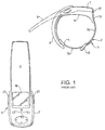
- a wrist-mounted portable telephone is disclosed in co-assigned patent GB2317300B.
- a telephone element 5 is arranged to be detached from a wrist band 2, allowing the user to use the detachable element in the same manner as a regular telephone.
- the removable telephone part 5 has a flexible element 6 which conforms to the shape of the strap when mounted, but which adopts a straighter configuration in use (as shown by the dotted lines).
- the antenna of the telephone is disposed within the flexible portion 6. This position for the antenna can cause problems.
- the flexible part 6 of the telephone also houses the earpiece, and due to the flexible nature of the housing, the user of the telephone may be tempted to hold the telephone by the flexible part so as to position the telephone more firmly against his ear. By doing so he may well shield the antenna with his hand, and so adversely affect its performance.
- a portable telephone assembly comprising first and second portions arranged to be mutually detachably interconnectable, the second portion being further arranged to be removably attachable to a user, the first portion comprising: a body portion; and an extendible portion movable between a relatively extended configuration and a relatively contracted configuration, wherein the extendible portion is biased towards the relatively extended configuration, such that when the first portion is detached from the second portion, the extendible portion is urged towards the relatively extended configuration.
- FIG. 2 shows an exploded view of a wrist-mounted telephone apparatus 100 according to an embodiment of the invention.
- the telephone apparatus 100 comprises two parts: a detachable telephone part 200, and a strap or bracelet-like part 300 for attachment to a user's wrist.
- the telephone part 200 is shown separate from the strap part 300 for clarity. In reality, in the mounted configuration shown, it would be located flush against the strap 300.
- the telephone part 200 comprises all the circuitry and elements normally associated with a portable radio telephone, as would be known by the skilled man.
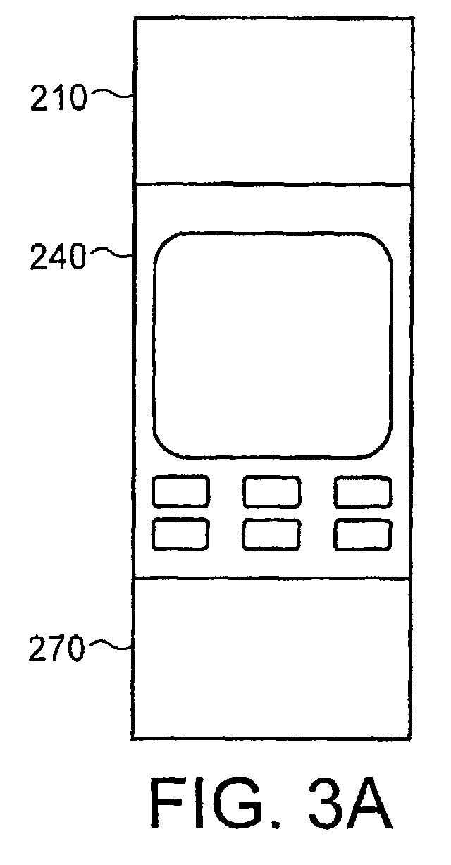
- the telephone part comprises three major portions: an upper portion 210, a central portion 240 and a lower portion 270.
- the profile of the telephone part 200 is generally curved, to provide a good fit with the bracelet part 300, which remains attached to the wrist when the telephone is in use.
- the bracelet part provides a convenient means by which the telephone may be carried about the user's person.
- the bracelet may also provide additional functionality in the manner of an additional power supply for the telephone.
- the bracelet part may be attached to the user's wrist by any conventional technique such as a buckle arrangement, or an elasticated strap.
- the telephone part there is no necessity for the telephone part to be curved as shown. Depending on the dimensions of the telephone part, it could be arranged to have a substantially flat profile. The profile chosen is matched by the attachment means of the bracelet part 300 so that reliable attachment and removal can be achieved.
- a microphone element is positioned in the lower portion 270.
- a battery (not shown) is positioned in the lower portion also.
- An earpiece and antenna are positioned in the upper portion 210.
- the central portion 240 accommodates the bulk of the circuitry of the telephone, including a display 250, and a number of user-operable input keys 260. The keys are for controlling the operation of the telephone, and are disposed on the front surface, as well as along one or more edges of the telephone 200.
- the telephone part 200 attaches firmly to the strap part 300.
- the user In order to use the telephone, the user must operate the release mechanism to free the telephone from the strap.
- the release mechanism can take many forms, and its exact operation is not critical to the operation of the invention.
- a release mechanism similar to that described in the aforementioned prior art document GB2317300B could be used.
- the mechanism therein described comprises two user-operable release latches which are situated on opposing edges of the telephone.
- the latches are arranged to engage with complementary parts on the bracelet and so lock the telephone to the bracelet.
- the user simply squeezes the two latches, which unlocks the telephone and allows it to be removed from the bracelet.
- the user To re-attach the telephone, the user simply needs to snap the telephone back into position, and so re-engage the latches.
- the upper portion 210 of the telephone containing the loudspeaker and the earpiece, is urged away from the central portion 240.
- the upper portion 210 is biased through the use of a spring, or similar resilient part, to adopt a position in which it is propelled away from the central portion.
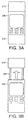
- FIGs 3a and 3b shows the telephone part 200 in its relatively contracted and extended positions, respectively.
- the telephone part 200 would assume the relatively contracted position when attached to the bracelet 300.
- the configuration of the telephone part 200 as shown in Figure 3b, with the upper portion in an extended position, is the natural configuration adopted by the telephone 200 when not attached to the bracelet 300.
- To maintain the telephone in the contracted configuration of Figure 3a requires the application of a constraining force.
- the constraining force is provided by interaction with the bracelet 300 when the telephone is attached to the bracelet.
- the internally located spring part propels the upper portion of the telephone 210 towards its relatively extended position.
- the upper portion 210 is supported by a pair of elongated supporting members 280.
- the supporting members 280 are formed as hollow tubular elements. This allows the electrical connections to the antenna and the earpiece to be routed separately through respective supporting members. This mitigates potential interference between the signals carried to and from the two separate elements.
- the action of the upper portion 210 adopting the extended position places the telephone in a configuration ready for use: the antenna and earpiece, which reside in the upper portion 210, are now situated away from the main body of the telephone.
- the earpiece is thus moved further away from the microphone, and assists in achieving a better audio performance. It also feels more natural to the user for the distance between earpiece and microphone to more closely resemble the actual distance between his ear and mouth.
- the user In the extended position, the user is encouraged to hold the telephone by the central portion 240, or possibly by the supporting members 280. This ensures that his hand is kept away from the antenna, located in upper portion 210. In this way, the signals transmitted and received by the antenna experience minimal disturbance from interaction with the user's hand.
- antenna used is not critical to the invention, but a suitable compact antenna is the plate or PIFA antenna.
- the telephone can detect its attachment status by sensing the relative position of the upper portion 210. In this way, it can use the sensed attachment status as a means of controlling certain functionality of the telephone.
- the telephone can be placed in an on-hook condition by re-attaching the telephone to the bracelet.
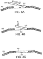
- Figure 4a shows the bracelet part 300 as the telephone part 200 is introduced for re-attachment.
- the top edge of the upper portion 210 is provided with a ridge or projection as shown.
- the upper portion 210 is inserted into the recess, and the central and lower portions (shown here as a single part for clarity) are pushed in the direction of the recess as indicated by the arrow.
- the force applied by the user acts to overcome the biasing force which tends to maintain the upper portion in the relatively extended position.
- the user then moves the telephone 200 in a downwards direction towards the bracelet 300.
- the aforementioned attachment means forming part of the telephone, engage with the complementary part 350 on the bracelet.
- the final position is as shown in Figure 4c.
- the telephone is secured in position by a combination of the effects of the projection and recess associated with the end of the upper portion 210, and the attachment system 350 associated with the central portion and the bracelet.
- the telephone is shown as having a generally flat profile for ease of understanding, but a curved, or other, profile could instead be adopted for the telephone.
- the present invention includes any novel feature or combination of features disclosed herein either explicitly or any generalisation thereof irrespective of whether or not it relates to the claimed invention or mitigates any or all of the problems addressed.
Landscapes
- Engineering & Computer Science (AREA)
- Computer Networks & Wireless Communication (AREA)
- Signal Processing (AREA)
- Telephone Set Structure (AREA)
- Mobile Radio Communication Systems (AREA)
Abstract
Description
Claims (12)
- A portable telephone assembly comprising first and second portions arranged to be mutually detachably interconnectable, the second portion being further arranged to be removably attachable to a user, the first portion comprising:wherein the extendible portion is biased towards the relatively extended configuration, such that when the first portion is detached from the second portion, the extendible portion is urged towards the relatively extended configuration.a body portion; andan extendible portion movable between a relatively extended configuration and a relatively contracted configuration,
- A telephone assembly as claimed in claim 1 wherein when the first and second parts are connected, the extendible portion adopts the relatively contracted configuration.
- A telephone assembly as claimed in claim 1 or 2 wherein the extendible portion comprises an antenna.
- A telephone assembly as claimed in any one of the preceding claims wherein the extendible portion comprises an earpiece.
- A telephone assembly as claimed in any one of the preceding claims wherein the body portion comprises a display.
- A telephone assembly as claimed in any one of the preceding claims wherein the extendible portion is supported on an elongate element.
- A telephone assembly as claimed in claim 6 wherein the elongate element is a hollow tubular element.
- A telephone assembly as claimed in claim 6 or 7 wherein the elongate element is disposed within the body portion when the extendible portion is in the relatively contracted configuration.
- A telephone assembly as claimed in any on of the preceding claims wherein the relative configuration of the extendible portion controls a function of the telephone.
- A telephone assembly as claimed in claim 9 wherein the relative configuration of the extendible portion controls the on-hook/off-hook status of the telephone.
- A telephone assembly as claimed in claim 10 wherein removing the first portion from the second portion answers an incoming call.
- A telephone assembly substantially as herein described and with particular reference to Figures 2 to 4 of the accompanying drawings.
Applications Claiming Priority (2)
| Application Number | Priority Date | Filing Date | Title |
|---|---|---|---|
| GB0101573 | 2001-01-22 | ||
| GB0101573A GB2371437A (en) | 2001-01-22 | 2001-01-22 | Wearable mobile phone with detachable extendible section |
Publications (2)
| Publication Number | Publication Date |
|---|---|
| EP1225750A2 true EP1225750A2 (en) | 2002-07-24 |
| EP1225750A3 EP1225750A3 (en) | 2003-06-04 |
Family
ID=9907230
Family Applications (1)
| Application Number | Title | Priority Date | Filing Date |
|---|---|---|---|
| EP02250173A Withdrawn EP1225750A3 (en) | 2001-01-22 | 2002-01-10 | Portable telephone |
Country Status (5)
| Country | Link |
|---|---|
| US (1) | US6707764B2 (en) |
| EP (1) | EP1225750A3 (en) |
| JP (1) | JP2002247171A (en) |
| CN (1) | CN1367599A (en) |
| GB (1) | GB2371437A (en) |
Cited By (2)
| Publication number | Priority date | Publication date | Assignee | Title |
|---|---|---|---|---|
| WO2004017612A3 (en) * | 2002-08-01 | 2004-06-03 | Siemens Ag | Mobile telephone comprising a fixing device for fixing said mobile telephone to the body of the user |
| ITVI20090177A1 (en) * | 2009-07-16 | 2011-01-17 | Massimiliano Bertolini | CELL PHONE INSERTED IN A BRACELET CLOCK WITH INCORPORATED ACCESSORY FUNCTIONS AND TO BRING TO WRIST |
Families Citing this family (37)
| Publication number | Priority date | Publication date | Assignee | Title |
|---|---|---|---|---|
| US20050013433A1 (en) * | 1997-06-02 | 2005-01-20 | Firooz Ghassabian | Wrist-mounted telephone device |
| US20040209657A1 (en) * | 1999-01-04 | 2004-10-21 | Yoram Ghassabian | Wrist-mounted telephone device |
| USD494556S1 (en) | 2002-03-01 | 2004-08-17 | Fossil, Inc. | Combined phone module and phone carriage |
| USD495675S1 (en) | 2002-05-20 | 2004-09-07 | Nokia Corporation | Pocket watch communicator |
| US20040062661A1 (en) * | 2002-09-27 | 2004-04-01 | Gary Hajdasz | Ambient air device |
| USD482671S1 (en) | 2002-11-02 | 2003-11-25 | Didonato Louis | Cell phone worn on wrist |
| USD501836S1 (en) * | 2002-11-15 | 2005-02-15 | U.S. Electronics, Inc. | Two-way radio wrist watch |
| USD489346S1 (en) | 2003-08-11 | 2004-05-04 | U.S. Electronics, Inc. | Two-way radio wrist watch |
| USD492658S1 (en) | 2003-08-29 | 2004-07-06 | U.S. Electronics, Inc. | Two-way radio wrist watch |
| USD496646S1 (en) | 2004-02-18 | 2004-09-28 | Us Electronics, Inc. | Two-way radio wrist watch with interchangeable faceplates |
| US7409236B1 (en) | 2005-08-25 | 2008-08-05 | Kyocera Wireless Corp. | Portable communication device with extendable visual display |
| USD565427S1 (en) * | 2006-01-20 | 2008-04-01 | Hourpower Watches, Llc | Combined watch and telephone |
| GB2439362A (en) * | 2006-06-19 | 2007-12-27 | Edward Nuttall | Detachable mobile phone wristwatch |
| USD595254S1 (en) * | 2008-04-10 | 2009-06-30 | Roberts Shirley A | Flexible mobile electronic device |
| US20090280861A1 (en) * | 2008-05-09 | 2009-11-12 | Ashana Sabana Nisha Khan | Multifunctional all-in-one detachable wrist wireless mobile communication device |
| USD621808S1 (en) * | 2009-03-10 | 2010-08-17 | Lg Electronics Inc. | Mobile phone |
| USD617661S1 (en) * | 2009-11-13 | 2010-06-15 | Casio Keisanki Kabushiki Kaisha | Wrist watch |
| US8432687B2 (en) * | 2011-02-23 | 2013-04-30 | Cole Patrick Schneider | Answer bracelet |
| US8705234B2 (en) * | 2011-02-23 | 2014-04-22 | Cole Patrick Schneider | Answer bracelet |
| US8249547B1 (en) | 2011-06-16 | 2012-08-21 | Albert Fellner | Emergency alert device with mobile phone |
| USD661275S1 (en) * | 2011-08-19 | 2012-06-05 | Cox Communications, Inc. | Mobile communications device with wrist band |
| USD709846S1 (en) * | 2012-09-07 | 2014-07-29 | Jonathan Oswaks | Wristband with communication device enclosed therein |
| USD718732S1 (en) * | 2012-11-09 | 2014-12-02 | Samsung Display Co., Ltd. | Mobile phone |
| USD718265S1 (en) * | 2012-11-09 | 2014-11-25 | Samsung Display Co., Ltd. | Mobile phone |
| WO2014134497A1 (en) | 2013-03-01 | 2014-09-04 | Rufus Armor, Llc | Wearable mobile device |
| USD709476S1 (en) * | 2013-03-29 | 2014-07-22 | Lg Electronics Inc. | Mobile phone |
| USD725068S1 (en) * | 2013-05-29 | 2015-03-24 | Samsung Electronics Co., Ltd. | Watch phone |
| JP1515100S (en) * | 2013-08-05 | 2017-12-25 | ||
| USD703069S1 (en) * | 2013-08-15 | 2014-04-22 | I.Am.Symbolic, Llc | Multi-media wireless watch |
| US9568891B2 (en) | 2013-08-15 | 2017-02-14 | I.Am.Plus, Llc | Multi-media wireless watch |
| USD730348S1 (en) * | 2014-01-09 | 2015-05-26 | Rufus Armor, Llc | Wearable mobile device |
| KR101480675B1 (en) * | 2014-03-24 | 2015-01-14 | 김중영 | Wristwatch type smart mobile terminal |
| USD756242S1 (en) * | 2014-05-23 | 2016-05-17 | Arm Ip Limited | Digital watch |
| USD757721S1 (en) * | 2014-05-30 | 2016-05-31 | Microsoft Corporation | Portion of a wearable electronic band |
| US20160116940A1 (en) * | 2014-10-23 | 2016-04-28 | Filip Technologies, Inc. | Band For A Wearable Device |
| US9191482B1 (en) | 2015-01-30 | 2015-11-17 | David Sidbury | Watch, mobile telephone and video camera system |
| USD825523S1 (en) | 2016-01-06 | 2018-08-14 | I.Am.Plus, Llc | Set of earbuds |
Family Cites Families (10)
| Publication number | Priority date | Publication date | Assignee | Title |
|---|---|---|---|---|
| US5224076A (en) * | 1992-10-16 | 1993-06-29 | Timex Corporation | Wristwatch radiotelephone |
| US5274613A (en) * | 1992-10-16 | 1993-12-28 | Timex Corporation | Wristwatch radiotelephone |
| US5381387A (en) * | 1994-05-06 | 1995-01-10 | At&T Corp. | Sound port for a wrist telephone |
| JP2595932B2 (en) * | 1994-05-18 | 1997-04-02 | 日本電気株式会社 | Portable radio |
| JPH089006A (en) * | 1994-06-17 | 1996-01-12 | Matsushita Electric Ind Co Ltd | Cordless telephone |
| GB2317300B (en) * | 1996-09-12 | 2000-08-16 | Nokia Mobile Phones Ltd | A handset |
| US6035035A (en) * | 1996-12-19 | 2000-03-07 | Classicom, Llc | Wrist mounted telephone device |
| FI112759B (en) * | 1998-03-18 | 2003-12-31 | Nokia Corp | Phone Telescope |
| GR1003029B (en) * | 1998-04-28 | 1998-12-10 | / | Mobile wrist telephone |
| JP3659846B2 (en) * | 1999-10-13 | 2005-06-15 | セイコーインスツル株式会社 | Arm portable information device |
-
2001
- 2001-01-22 GB GB0101573A patent/GB2371437A/en not_active Withdrawn
-
2002
- 2002-01-10 EP EP02250173A patent/EP1225750A3/en not_active Withdrawn
- 2002-01-14 US US10/043,334 patent/US6707764B2/en not_active Expired - Lifetime
- 2002-01-21 JP JP2002011247A patent/JP2002247171A/en not_active Withdrawn
- 2002-01-21 CN CN02102425A patent/CN1367599A/en active Pending
Cited By (2)
| Publication number | Priority date | Publication date | Assignee | Title |
|---|---|---|---|---|
| WO2004017612A3 (en) * | 2002-08-01 | 2004-06-03 | Siemens Ag | Mobile telephone comprising a fixing device for fixing said mobile telephone to the body of the user |
| ITVI20090177A1 (en) * | 2009-07-16 | 2011-01-17 | Massimiliano Bertolini | CELL PHONE INSERTED IN A BRACELET CLOCK WITH INCORPORATED ACCESSORY FUNCTIONS AND TO BRING TO WRIST |
Also Published As
| Publication number | Publication date |
|---|---|
| CN1367599A (en) | 2002-09-04 |
| US20020105859A1 (en) | 2002-08-08 |
| EP1225750A3 (en) | 2003-06-04 |
| US6707764B2 (en) | 2004-03-16 |
| JP2002247171A (en) | 2002-08-30 |
| GB2371437A (en) | 2002-07-24 |
| GB0101573D0 (en) | 2001-03-07 |
Similar Documents
| Publication | Publication Date | Title |
|---|---|---|
| US6707764B2 (en) | Portable telephone | |
| US6757389B2 (en) | Wrist-mounted telephone device | |
| EP1225751B1 (en) | Portable telephone | |
| US7529155B2 (en) | Wristwatch with earphone function | |
| US6681014B1 (en) | Wrist-mounted telephone device | |
| JPH10126475A (en) | Handset | |
| US20040209657A1 (en) | Wrist-mounted telephone device | |
| US6535605B1 (en) | Wrist-worn cellular phone device having multi-sectioned keypad | |
| US6850773B1 (en) | Antenna system for a wrist communication device | |
| US20050013433A1 (en) | Wrist-mounted telephone device | |
| US6973185B2 (en) | Mobile communications device to be worn on the wrist having flexible battery strap | |
| JPWO2005096599A1 (en) | Communication device using bone conduction speaker | |
| CN101095369A (en) | Wrist watch with earphone function | |
| CN100518200C (en) | portable communication terminal | |
| AU774812B2 (en) | A wrist communication device having multi-sectioned keypad and antenna system | |
| JPH0955679A (en) | Wrist watch radio telephone system | |
| KR19990040480A (en) | Wrist watch personal digital radio | |
| JPH03162024A (en) | mobile phone | |
| JP2006086564A (en) | Mobile communication apparatus | |
| JP2000286939A (en) | Portable wristwatch radio telephone set | |
| KR200262103Y1 (en) | wireless apparatus having watch function | |
| IL119873A (en) | Wrist wrapped telephone device | |
| JPH0637874A (en) | Portable telephone set | |
| NZ531324A (en) | A wrist communication device having a wireless connection with a multi-sectioned keypad | |
| IL120605A (en) | Wrist mounted telephone device |
Legal Events
| Date | Code | Title | Description |
|---|---|---|---|
| PUAI | Public reference made under article 153(3) epc to a published international application that has entered the european phase |
Free format text: ORIGINAL CODE: 0009012 |
|
| AK | Designated contracting states |
Kind code of ref document: A2 Designated state(s): AT BE CH CY DE DK ES FI FR GB GR IE IT LI LU MC NL PT SE TR |
|
| AX | Request for extension of the european patent |
Free format text: AL;LT;LV;MK;RO;SI |
|
| PUAL | Search report despatched |
Free format text: ORIGINAL CODE: 0009013 |
|
| AK | Designated contracting states |
Designated state(s): AT BE CH CY DE DK ES FI FR GB GR IE IT LI LU MC NL PT SE TR |
|
| AX | Request for extension of the european patent |
Extension state: AL LT LV MK RO SI |
|
| 17P | Request for examination filed |
Effective date: 20031204 |
|
| AKX | Designation fees paid |
Designated state(s): AT BE CH CY DE DK ES FI FR GB GR IE IT LI LU MC NL PT SE TR |
|
| AXX | Extension fees paid |
Extension state: SI Payment date: 20031204 Extension state: RO Payment date: 20031204 Extension state: MK Payment date: 20031204 Extension state: LV Payment date: 20031204 Extension state: LT Payment date: 20031204 Extension state: AL Payment date: 20031204 |
|
| STAA | Information on the status of an ep patent application or granted ep patent |
Free format text: STATUS: THE APPLICATION HAS BEEN WITHDRAWN |
|
| 18W | Application withdrawn |
Effective date: 20041014 |