EP1225687A1 - Output switch circuit of generator - Google Patents
Output switch circuit of generator Download PDFInfo
- Publication number
- EP1225687A1 EP1225687A1 EP00969938A EP00969938A EP1225687A1 EP 1225687 A1 EP1225687 A1 EP 1225687A1 EP 00969938 A EP00969938 A EP 00969938A EP 00969938 A EP00969938 A EP 00969938A EP 1225687 A1 EP1225687 A1 EP 1225687A1
- Authority
- EP
- European Patent Office
- Prior art keywords
- generator
- field
- phase
- bridge rectifier
- coil
- Prior art date
- Legal status (The legal status is an assumption and is not a legal conclusion. Google has not performed a legal analysis and makes no representation as to the accuracy of the status listed.)
- Withdrawn
Links
- 238000010248 power generation Methods 0.000 claims abstract description 51
- 230000004907 flux Effects 0.000 claims abstract description 28
- 230000008859 change Effects 0.000 claims abstract description 10
- 239000007858 starting material Substances 0.000 claims description 20
- 238000001514 detection method Methods 0.000 claims description 2
- 101100365087 Arabidopsis thaliana SCRA gene Proteins 0.000 abstract description 31
- 101150105073 SCR1 gene Proteins 0.000 abstract description 31
- 101100134054 Saccharomyces cerevisiae (strain ATCC 204508 / S288c) NTG1 gene Proteins 0.000 abstract description 31
- 101000668165 Homo sapiens RNA-binding motif, single-stranded-interacting protein 1 Proteins 0.000 abstract description 27
- 102100039692 RNA-binding motif, single-stranded-interacting protein 1 Human genes 0.000 abstract description 27
- 238000000034 method Methods 0.000 description 35
- 230000005669 field effect Effects 0.000 description 18
- 238000010586 diagram Methods 0.000 description 11
- XEEYBQQBJWHFJM-UHFFFAOYSA-N Iron Chemical compound [Fe] XEEYBQQBJWHFJM-UHFFFAOYSA-N 0.000 description 6
- 230000003071 parasitic effect Effects 0.000 description 6
- 101100484930 Saccharomyces cerevisiae (strain ATCC 204508 / S288c) VPS41 gene Proteins 0.000 description 5
- 230000004048 modification Effects 0.000 description 5
- 238000012986 modification Methods 0.000 description 5
- 229910052742 iron Inorganic materials 0.000 description 3
- 230000009467 reduction Effects 0.000 description 3
- 230000000694 effects Effects 0.000 description 2
- 238000010304 firing Methods 0.000 description 2
- 102100036302 C-C chemokine receptor type 6 Human genes 0.000 description 1
- 101000716068 Homo sapiens C-C chemokine receptor type 6 Proteins 0.000 description 1
- 230000020169 heat generation Effects 0.000 description 1
- 239000000696 magnetic material Substances 0.000 description 1
- 230000003252 repetitive effect Effects 0.000 description 1
Images


Classifications
-
- H—ELECTRICITY
- H02—GENERATION; CONVERSION OR DISTRIBUTION OF ELECTRIC POWER
- H02P—CONTROL OR REGULATION OF ELECTRIC MOTORS, ELECTRIC GENERATORS OR DYNAMO-ELECTRIC CONVERTERS; CONTROLLING TRANSFORMERS, REACTORS OR CHOKE COILS
- H02P9/00—Arrangements for controlling electric generators for the purpose of obtaining a desired output
- H02P9/14—Arrangements for controlling electric generators for the purpose of obtaining a desired output by variation of field
- H02P9/26—Arrangements for controlling electric generators for the purpose of obtaining a desired output by variation of field using discharge tubes or semiconductor devices
- H02P9/30—Arrangements for controlling electric generators for the purpose of obtaining a desired output by variation of field using discharge tubes or semiconductor devices using semiconductor devices
- H02P9/305—Arrangements for controlling electric generators for the purpose of obtaining a desired output by variation of field using discharge tubes or semiconductor devices using semiconductor devices controlling voltage
Definitions
- the present invention relates to a technique for switching an output of a generator. More particularly, in an output control method of a generator employing a magnetic field method using a magnet only as a magnetic field source or employing a hybrid field control method using both of a magnet and a field coil, the present invention relates to a technique effectively applied to an output switch circuit of a generator, which is suitable for controlling a power generation output to a lower level.
- a generator employing the hybrid field control method is constituted of, for example, a stator having three-phase power generation coils wound thereto, a rotor rotatably provided around the stator, a magnet provided to the rotor, a bridge rectifier circuit comprising a plurality of diodes for rectifying a current generated by the three-phase generation coils, a field control unit for controlling effective flux using the magnet and the field coil, and the like, and the generator can control the power generation output in a certain range by changing the magnitude and direction of the field current conducted to the field coil to change the effective flux of the generator.
- the generator employing the hybrid field control method when used as, for example, a generator of a motorcycle, it is impossible to control the power generation output in a target range because of the wide range of its rotations to be used (e.g., 1000 rpm to 10000 rpm). In particular, such a generator has a problem that the output at high rotations can not be controlled properly.
- the power generation output is controlled by means of a bridge rectifier circuit 2c comprising a plurality of diodes D1 to D6 for rectifying the current generated by three-phase generation coils 1 and of a field control circuit 5 for controlling the effective flux by using a magnet and a field coil 4, and the characteristic of the power generation output is shown in FIG. 7 for example.
- the range in which the output can be controlled is limited in a certain range even if the field output is controlled in a range of +X(AT) to -X(AT). In other words, it is impossible to control the output lower than B (A) at A (rpm).
- Japanese Patent Laid-Open Publication No. 60-118095 is known in which an output of a three-phase generator is constituted of thyristors instead of conventionally-used bridge diodes, and six thyristors are controlled by the firing angle control or the so-called open regulator when controlling the power generation output.
- the current more than required electric power is cut by the control of the thyristors in a state where the number of effective coils of the generator remains unchanged and the power generation potential is kept high.
- a part of the diodes is replaced by a switching device and this switching device is turned on and off, thereby changing the number of effective coils, and thus switching the power generation potential of the generator itself. So, this technique and the present invention are different from each other.
- the present invention can cope with such problems as the iron loss.
- a generator also functioning as a starter motor that is operated as a motor when starting an engine and is operated as a generator after starting the engine
- a starter motor when the generator satisfies the function of a starter motor, excessive current is inevitably generated as a generator.
- a method of separately providing a starter and a generator coil or a method that the excessive current generated when generating electric power is short-circuited at a transistor positioning at a low side of a driver can be used.
- the size of the generator is increased.
- the latter since heat generation is inevitable due to the short circuit of the excessive current, the latter is inefficient.
- the friction in the engine may be increased.
- an object of the present invention is to provide an output switch circuit of a generator capable of switching a power generation potential of a generator itself by appropriately arranging the configuration of a bridge rectifier circuit, and further, capable of controlling a power generation voltage to be constant by changing the number of effective fluxes of a field coil.
- a part of the devices in a bridge rectifier circuit is replaced from a diode to a switching device, and the switching device is turned on and off so as to change the number of the effective coils of the generator, more specifically, the power generation potential of the generator itself is changed. Furthermore, by combining this with the conventional hybrid field control in which effective flux is changed by the field coil, the excessive output that is a problem in the prior art can be suppressed by the magnetic flux from a smaller field coil than that in the prior art.
- a bridge rectifier circuit is constituted of at least one switching device with regard to a bridge structure constituted of a plurality of diodes, and the output switch circuit is provided with a control unit for changing the number of effective coils of a multi-phase generation coil by turning on and off the switching device (power generation operation is performed in a state where the switching device is turned on or off). Therefore, the power generation potential of the generator itself can be switched by the control unit.
- a bridge rectifier circuit is constituted of at least one switching device with regard to a bridge structure constituted of a plurality of diodes, and the output switch circuit is provided with a field control unit for controlling effective flux by using a permanent magnet and a field coil arranged near the generation coil, in addition to the control unit for changing the number of effective coils of a multi-phase generation coil by turning on and off the switching device. Therefore, the power generation potential of the generator itself can be switched by the control unit, and also, the effective flux by the field coil is changed by the field control unit, thereby enabling to control the power generation voltage to be constant.
- a bridge rectifier circuit is constituted of at least one switching device with regard to that constituted of a plurality of diodes, and the output switch circuit is provided with a control unit for changing the number of effective coils of a multi-phase armature coil by turning on and off the switching device; and a field control unit for controlling effective flux by using a permanent magnet and a field coil arranged near the armature coil.
- the output switch circuit of the present invention is applied to the multi-phase generator also functioning as a starter motor, the power generation potential of the generator itself can be switched by the control unit, and also, the effective flux by the field coil can be changed by the field control unit, thereby enabling to control the power generation voltage to be constant.
- the control method in this constitution proceeds as follows. That is, rotations of a generator of an engine are detected by the control unit, the switching device is switched on and off at the predetermined rotations determined based on the number of the effective switching devices of the bridge rectifier circuit corresponding to the range of the rotations, and then the magnetic field control unit performs the field control, thereby enabling to change the magnitude and direction of a field current so as to control the generation voltage to be constant.
- another control method may be as follows. That is, a voltage to be controlled to be constant such as a battery voltage is previously monitored by the control unit, and when it becomes impossible to reduce the voltage by the field control by the field control unit, the control unit can turn off the switching device.
- the output switch circuit of a generator according to the present invention can obtain the following advantages.
- FIG. 1 is a circuit diagram showing a control system including an output switch circuit of a generator according to the first embodiment of the present invention
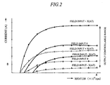
- FIG. 2 is a characteristic diagram showing the characteristic of the power generation output in a generator of this embodiment
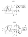
- FIGs. 3 and 4 are circuit diagrams showing modification examples of the output switch circuit.
- the generator in this embodiment is used by connecting with, for example, a motorcycle engine or a general-purpose engine, and is provided with Y-connected three-phase generation coils 1, a bridge rectifier circuit 2 for rectifying the current generated by the generation coils 1, a thyristor gate control circuit (control unit) 3 for controlling thyristors of the bridge rectifier circuit 2, a field coil 4 arranged near the generation coils 1, a field control circuit (field control unit) 5 for controlling the effective flux by means of the filed coil 4 and a magnet (permanent magnet), a rotation sensor 6 for detecting the number of the rotations, a battery 7, and the like.
- an electric power is generated between the generation coil 1 and the magnet by the rotation of the generator, and the generated current is rectified and then supplied to a load 9 through a switch 8.
- the three-phase generation coils 1 composed of U-phase, V-phase, and W-phase coils are wound to each stator, and a rotor opposite to the stator is rotatably provided, respectively.
- This rotor is provided with a plurality of magnets magnetized to the same pole and field parts having a plurality of controlling poles made of a magnetic material between the magnets. Magnetic flux forming a closed magnetic circuit through the controlling poles of the field part and combined with the magnetic flux by the magnet is generated by the field coil 4 by the control of the field control circuit 5.
- the rotor of the generator is directly linked with a crankshaft of an engine.
- the bridge rectifier circuit 2 is formed with diodes and with at least one switching device in contrast to the bridge structure composed of a plurality of diodes.
- one of three bridge lines is replaced by thyristors SCR1 and SCR2 functioning as switching devices, and the bridge rectifier circuit 2 is constituted of four diodes D1 to D4 and the two thyristors SCR1 and SCR2.
- Cathode sides of the diodes D1 and D3 and that of the thyristor SCR1 are commonly connected to the power supply potential, and the anode sides of the diodes D2 and D4 and that of the thyristor SCR2 are commonly connected to the ground potential, respectively.
- Anodes of the diodes D1 and D3 and that of the thyristor SCR1 and the cathodes of the diodes D2 and D4 and that of the thyristor SCR2 are respectively connected to each other.
- Each connection node between the diodes D1 and D2, diodes D3 and D4, and thyristors SCR1 and DCR2 is connected to the U phase, V phase, and W phase of the generation coils 1, respectively.
- Each of the gates of the thyristors SCR1 and SCR2 of the bridge rectifier circuit 2 is connected to the thyristor gate control circuit 3 by which the gates are controlled.
- the thyristor gate control circuit 3 turns on and off the thyristors SCR1 and SCR2 to change the number of the effective coils of the three-phase generation coils 1, which makes it possible to switch the power generation potential of the generator itself.
- a rotation sensor 6 is connected to the thyristor gate control circuit 3 to detect the rotations of the generator and the thyristors SCR1 and SCR2 are switched on and off at the predetermined rotations based on the number of the effective thyristors SCR1 and SCR2 of the bridge rectifier circuit 2 corresponding to the range of the rotations.
- the field coil 4 is connected to the field control circuit 5, and the field control circuit 5 performs the magnetic field control of the field coil 4 to generate the magnetic flux to be combined with the magnetic flux by a magnet, and then, the magnitude and the direction of the field current is changed so as to keep the voltage of the battery 7 almost constant, thereby enabling to control the power generation voltage to be constant.
- the hybrid field control method in which a magnet and the field coil 4 are used as a magnetic field source is adapted.
- the power generation potential of the generator itself can be switched by the thyristor gate control circuit 3, and further, the power generation voltage can be controlled to be constant by changing the effective flux by the field coil 4 by the field control circuit 5.
- the generator is started up by starting the engine directly linked with a rotor via a crankshaft. More specifically, when the engine is started, the rotor linked with the crankshaft rotates around a stator. Thus, the magnetic flux of the controlling pole formed by the magnetic flux of the magnet as a rotor and by the conduction to the field coil 4 is to form a rotating magnetic field, and thereby, the generation coil 1 is turned off. As a result, an electromotive force is generated in the generation coils 1. The electromotive force of the generation coils 1 is charged in the battery 7 after being rectified in the bridge rectifier circuit 2 or supplied to the desired load 9 after taken out through the switch 8.
- the switch on and off of the thyristors SCR1 and SCR2 of the bridge rectifier circuit 2 by the thyristor gate control circuit 3 can be performed as described below.
- the switch on and off of the thyristors SCR1 and SCR2 makes it possible to control the capability of the generator.
- the control of the current flowing through the field coil 4 makes it possible to control the power generation output in a wider range than that in the prior art.
- the characteristic of the power generation output at this time is shown in FIG. 2. More specifically, contrary to the example shown in FIG. 7 in which the controllable range of the output is limited in a certain range even if the field output is controlled in a range of +X(AT) to -X(AT), it becomes possible to control the output lower than B (A) at A (rpm) in this example as shown in FIG. 2.
- the controllable range of the output can be expanded to the range represented by dotted lines (both of the thyristors SCR1 and SCR2 are in an OFF state).
- FIG. 3 is different from that of FIG. 1 in the position of the bridge lines replaced by thyristors
- FIG. 4 shows an example in which field effect transistors are used instead of the thyristors.
- thyristors SCR1 and SCR2 are replaced by thyristors SCR1 and SCR2.
- Cathode side of the diode D1 and those of the thyristors SCR1 and SCR2 are commonly connected to the power supply potential, and the anode sides of the diodes D2 to D4 are commonly connected to the ground potential.
- the anode of the diode D1 and those of the thyristors SCR1 and SCR2 and the cathodes of the diodes D2 to D4 are respectively connected to each other.
- connection nodes between the diodes D1 and D2, the thyristor SCR1 and the diode D3, and thyristor SCR2 and the diode D4 is connected to the U phase, V phase, and W phase of the generation coils 1, respectively.
- field effect transistors FET1 and FET2 are used in a bridge rectifier circuit 2b, and the field effect transistors FET1 and FET2 are connected to diodes D5 and D6 in series so as to have the same forward direction.
- the cathode sides of the diodes D1, D3, and D5 are commonly connected to the power supply potential.
- the anodes of the diodes D1 and D3 and the cathodes of the diodes D2 and D4 are respectively connected to each other, and the anode sides of the diodes D2 and D4 are commonly connected to the ground potential.
- the anode of the diode D5 is connected to the source of the field effect transistor FET1 and the drain of the field effect transistor FET1 is connected to the cathode of the diode D6. Further, the anode of the diode D6 is connected to the source of the field effect transistor FET2 and the drain of the field effect transistor FET2 is connected to the ground potential.
- Each connection node between the diodes D1 and D2, diodes D3 and D4, and field effect transistor FET1 and the diode D6 is connected to the U phase, V phase, and W phase of the generation coils 1, respectively.
- the same operations as those obtained in the constitution shown in FIG. 1 can be achieved by turning on or off both of the field effect transistors FET1 and FET2 by the control of a transistor gate control circuit 10, or turning off only one of the transistors. Therefore, the switch on and off of the field effect transistors makes it possible to change the capability of the generator.
- the generator of this embodiment is provided with: the bridge rectifier circuit 2, 2a, or 2b in which at least one of the plurality of diodes of the bridge structure is replaced by a switching device such as a thyristor and a field effect transistor; the thyristor gate control circuit 3 of the thyristor; the transistor gate control circuit 10 of the field effect transistor; the field coil 4; and the field control circuit 5. Therefore, it is possible to control the generator by the use of the thyristor gate control circuit 3 and the field control circuit 5 or the transistor gate control circuit 10 and the field control circuit 5. Accordingly, wider output control can be achieved in comparison to the output control by only the input by means of the magnitude and direction of the current flown into the field coil 4. A particular effect can be obtained in the control to suppress the excessive output.
- the capability of the generator is changed in the thyristor gate control circuit 3 or in the transistor gate control circuit 10 and then the generator is controlled, the magnetomotive force of.the field coil 4 can be reduced. Therefore, the size of the generator can be reduced. As a result, the miniaturization, the weight saving, and the cost down can be achieved.
- the power generation efficiency as a system can be improved. Meanwhile, if it is not required to improve the power generation efficiency, the reduction of the field input can be achieved. Furthermore, the heat generated in the field coil 4 can be reduced.
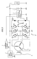
- FIG. 5 is a circuit diagram of a control system including an output switch circuit of a generator also functioning as a starter motor according to the second embodiment of the present invention.
- the generator of this embodiment is used by connecting with, for example, a motorcycle engine or a general-purpose engine.
- the output switch circuit of this embodiment is different from that of the first embodiment in that the output switch circuit of the second embodiment is applied to a multi-phase generator also functioning as a starter motor, which is operated as a motor when starting an engine and is operated as a generator after starting the engine.
- the electric power is generated between the permanent magnet and the armature coil by the rotation of the rotor.
- the multi-phase generator also functioning as a starter motor of this embodiment is provided with a three-phase armature coil 11 made of Y-connected brushless motors, a brushless motor driver and bridge rectifier circuit 12 for controlling the conduction of the armature coil 11 and rectifying the current generated by the armature coil 11, and with, as similar to those in the first embodiment, the thyristor gate control circuit (control unit) 3, the field coil 4, the field control circuit (field control unit) 5, the rotation sensor 6, the battery 7, and with a rotor position sensor (not shown), and a FET gate drive circuit (not shown) for driving a motor.
- the multi-phase generator is operated as a motor when starting an engine and operated as a generator after starting the engine. Further, the multi-phase generator has such a constitution that an electric power is generated between the magnet and the armature coil 11 by the rotation of the generator and the generated current is rectified and then supplied to the load 9 through the switch 8.
- the brushless motor driver and bridge rectifier circuit 12 has a conduction control function for conducting a current for forming a rotating magnetic field to the armature coil 11 based on the detection result by the rotor position sensor and has a rectification function for rectifying the current generated in the armature coil 11. Also, the brushless motor driver and bridge rectifier circuit 12 comprises six field effect transistors FET 11 to FET16, six parasitic diodes D11 to D16 connected in parallel to the field effect transistors FET 11 to FET16, a switch S11 switched depending on whether the generator is operated as a starter motor or a generator, two thyristors SCR11 and SCR12 functioning as switching devices when the generator is operated as a generator.
- the brushless motor driver and bridge rectifier circuit 12 has a constitution in which at least one of the plurality of parasitic diodes D11 to D16 constituting the bridge structure is replaced by a switching device at the time when the generator is operated as a generator.
- one line of the three lines of the bridge lines is replaced by the thyristors SCR11 and SCR12.
- the switch S11 of the brushless motor driver and bridge rectifier circuit 12 when operated as a starter motor, is connected to the A side, gate signals are transmitted from the FET gate drive circuit to the field effect transistors FET11 to FET16 based on the signals from the rotor position sensor so as to form the rotating magnetic field, and the commutation control of the conduction to the armature coil 11 of the brushless motor is performed to rotate the brushless motor in the desired direction.
- the engine directly linked with the rotor via a crankshaft is thereby started.
- the switch S11 of the brushless motor driver and bridge rectifier circuit 12 is switched to the B side, and thus, one line (FET 15 and FET16) of the parasitic diodes D11 to D16 in the three lines of the field effect transistors FET 11 to FET16 are replaced by the thyristors SCR11 and SCR12.
- the three-phase full-wave rectification is performed when both of the thyristors SCR11 and SCR12 are turned on by the control of the thyristor gate control circuit 3, and the single-phase full-wave rectification is performed when both of the thyristors SCR11 and SCR12 are turned off by the control of the thyristor gate control circuit 3. In short, it is possible to control the capability of the generator.
- the thyristors SCR11 and SCR12 are switched on and off by the thyristor gate control circuit 3 to change the number of effective coils of the three-phase armature coils 11, thereby enabling to switch the power generation potential of the generator itself.
- the magnetic field of the field coil 4 is controlled by the field control circuit 5 and the magnitude and the direction of the field current is changed so as to keep the voltage of the battery 7 almost constant, thereby enabling to control the generation voltage to be constant.
- the generator is provided with a brushless motor driver and bridge rectifier circuit 12 capable of replacing at least one parasitic diode by a switching device such as a thyristor in a bridge structure constituted of a plurality of parasitic diodes, more specifically, capable of replacing one line of the parasitic diodes D11 to D16 in the three lines of the field effect transistors FET 11 to FET16 by the thyristors SCR11 and SCR12 by means of the switch S11 at the time when the generator is operated as a generator; the thyristor gate control circuit 3 of this thyristor; the field coil 4; and the field control circuit 5. Therefore, since the control using both of the thyristor gate control circuit 3 and the field control circuit 5 can be performed, the same advantages as those of the first embodiment can be obtained.
- the present invention is not limited to the foregoing embodiments and various changes and modifications can be made therein within the scope of the invention.
- descriptions are made for the examples in which the output switch circuit of a generator of the present invention is applied to a generator employing a hybrid field control method using a magnet and a field coil as a magnetic field source and to a generator also functioning as a starter motor employing the same hybrid field control method.
- the application of the present invention is not limited to this. It is also possible to apply the present invention to a generator employing a field method using a magnet only as a magnetic field source without providing any field coil and field control circuit and also to a generator also functioning as a starter motor employing the same field method.
- a bridge rectifier circuit or a brushless motor driver and bridge rectifier circuit is constituted of at least one switching device in contrast to that constituted of a plurality of diodes, and a control unit for changing the number of effective coils of a multi-phase generation coils by turning on and off the switching device is provided. Therefore, the power generation potential of the generator itself can be switched.
- IGBT can be used as a switching device instead of a thyristor.
- a mechanical switch such as a relay can be used instead of a field effect transistor.
- connection of the multi-phase generation coils is not limited to the star connection (Y-connection) and delta connection is also available.
- the output switch circuit of the present invention can be applied to the multi-phase generator having four or more phases.
- the present invention can reduce the capability of a generator by turning off a switching device at the time of excessive output to partially limit the multi-phase current of the generator.
- the output is controlled to be constant by the field coil. Therefore, it becomes possible to control the power generation output in a wider range than that in the prior art. More specifically, the control range of the power generation output is expanded to the lower side.
- the magnetic field is controlled in a state where the generation capability is previously lowered, the magnetomotive force of the field coil can be lowered than that in the prior art. Therefore, it becomes possible to make the field coil smaller in size.
- the output switch circuit of a generator according to the present invention can be effectively used in, for example, an output control method of a generator employing a field method using a magnet only as a magnetic field source or a hybrid field control method in which both of a magnet and a field coil are used. More particularly, the present invention can be widely applied to an output switch circuit of a generator which is preferably used to control the power generation output to a lower level.
Landscapes
- Engineering & Computer Science (AREA)
- Power Engineering (AREA)
- Control Of Eletrric Generators (AREA)
Abstract
A generator capable of switching its power generation
potential while controlling to keep a constant output by
changing the effective flux of field coils. The generator,
which is used with a motorcycle engine or a general-purpose
engine, comprises three-phase generation coils (1), a bridge
rectifier circuit (2) for rectifying the current generated by
the coil, a thyristor gate control circuit (3) for controlling
thyristors of the bridge rectifier circuit, field coils (4)
arranged near the coils, and a field control circuit (5) for
controlling the effective flux by means of the coils and a
magnet. The bridge rectifier circuit includes a plurality of
diodes and a series of thyristors (SCR1, SCR2) so that the
thyristors may be turned on and off to change the number of
effective ones of the coils (1).
Description
The present invention relates to a technique for
switching an output of a generator. More particularly, in an
output control method of a generator employing a magnetic
field method using a magnet only as a magnetic field source or
employing a hybrid field control method using both of a magnet
and a field coil, the present invention relates to a technique
effectively applied to an output switch circuit of a generator,
which is suitable for controlling a power generation output to
a lower level.
Heretofore, a generator employing the hybrid field
control method is constituted of, for example, a stator having
three-phase power generation coils wound thereto, a rotor
rotatably provided around the stator, a magnet provided to the
rotor, a bridge rectifier circuit comprising a plurality of
diodes for rectifying a current generated by the three-phase
generation coils, a field control unit for controlling
effective flux using the magnet and the field coil, and the
like, and the generator can control the power generation
output in a certain range by changing the magnitude and
direction of the field current conducted to the field coil to
change the effective flux of the generator.
However, in the above-mentioned generator employing the
hybrid field control method, it is difficult to reduce the
output completely to zero because of the use of a magnet as a
magnetic field source. Also, it is required to increase the
magnetic flux of the field coil in order to further suppress
(reduce) the output, which results in the increase of the
field coil in size (because it is necessary to increase an
ampere-turn value). Such large coils hinder the reduction of
the entire size of the generator.
Also, when the generator employing the hybrid field
control method is used as, for example, a generator of a
motorcycle, it is impossible to control the power generation
output in a target range because of the wide range of its
rotations to be used (e.g., 1000 rpm to 10000 rpm). In
particular, such a generator has a problem that the output at
high rotations can not be controlled properly.
For example, in a generator employing the hybrid field
control method and having a constitution as described in FIG.
6, the power generation output is controlled by means of a
bridge rectifier circuit 2c comprising a plurality of diodes
D1 to D6 for rectifying the current generated by three-phase
generation coils 1 and of a field control circuit 5 for
controlling the effective flux by using a magnet and a field
coil 4, and the characteristic of the power generation output
is shown in FIG. 7 for example. More specifically, in this
example of the power generation characteristic, the range in
which the output can be controlled is limited in a certain
range even if the field output is controlled in a range of
+X(AT) to -X(AT). In other words, it is impossible to control
the output lower than B (A) at A (rpm).
In addition, as a technique relating to the control of
the power generation output of a generator, Japanese Patent
Laid-Open Publication No. 60-118095 is known in which an
output of a three-phase generator is constituted of thyristors
instead of conventionally-used bridge diodes, and six
thyristors are controlled by the firing angle control or the
so-called open regulator when controlling the power generation
output. In this technique, the current more than required
electric power is cut by the control of the thyristors in a
state where the number of effective coils of the generator
remains unchanged and the power generation potential is kept
high. Meanwhile, in the present invention, a part of the
diodes is replaced by a switching device and this switching
device is turned on and off, thereby changing the number of
effective coils, and thus switching the power generation
potential of the generator itself. So, this technique and the
present invention are different from each other.
Furthermore, since an open control by the firing angle
control of the thyristors is used in the technique in the
Publication, there is a possibility that the iron loss is
increased. In the present invention, however, it is possible
to control the power generation output while flowing the
current and reducing the magnetic flux. Therefore, the
present invention can cope with such problems as the iron loss.
Also, in a generator also functioning as a starter
motor that is operated as a motor when starting an engine and
is operated as a generator after starting the engine, when the
generator satisfies the function of a starter motor, excessive
current is inevitably generated as a generator. For its
solution, a method of separately providing a starter and a
generator coil or a method that the excessive current
generated when generating electric power is short-circuited at
a transistor positioning at a low side of a driver can be used.
However, in the former, since each of the starter and the
generator must have a coil and the driver and the rectifier
circuit are separately provided, the size of the generator is
increased. Also, in the latter, since heat generation is
inevitable due to the short circuit of the excessive current,
the latter is inefficient. In addition, the friction in the
engine may be increased.
In such a circumstance, with focusing on the problems
of the iron loss and the power generation potential of the
generator itself as described above, an object of the present
invention is to provide an output switch circuit of a
generator capable of switching a power generation potential of
a generator itself by appropriately arranging the
configuration of a bridge rectifier circuit, and further,
capable of controlling a power generation voltage to be
constant by changing the number of effective fluxes of a field
coil.
For the solution of the above problems, in the present
invention, a part of the devices in a bridge rectifier circuit
is replaced from a diode to a switching device, and the
switching device is turned on and off so as to change the
number of the effective coils of the generator, more
specifically, the power generation potential of the generator
itself is changed. Furthermore, by combining this with the
conventional hybrid field control in which effective flux is
changed by the field coil, the excessive output that is a
problem in the prior art can be suppressed by the magnetic
flux from a smaller field coil than that in the prior art.
More specifically, in an aspect of an output switch
circuit of a generator according to the present invention used
in the magnetic field method using a magnet only as a magnetic
field source, a bridge rectifier circuit is constituted of at
least one switching device with regard to a bridge structure
constituted of a plurality of diodes, and the output switch
circuit is provided with a control unit for changing the
number of effective coils of a multi-phase generation coil by
turning on and off the switching device (power generation
operation is performed in a state where the switching device
is turned on or off). Therefore, the power generation
potential of the generator itself can be switched by the
control unit.
Also, in another aspect of an output switch circuit of
a generator according to the present invention used in the
hybrid field control method using a magnet and a field coil as
magnetic field sources, a bridge rectifier circuit is
constituted of at least one switching device with regard to a
bridge structure constituted of a plurality of diodes, and the
output switch circuit is provided with a field control unit
for controlling effective flux by using a permanent magnet and
a field coil arranged near the generation coil, in addition to
the control unit for changing the number of effective coils of
a multi-phase generation coil by turning on and off the
switching device. Therefore, the power generation potential
of the generator itself can be switched by the control unit,
and also, the effective flux by the field coil is changed by
the field control unit, thereby enabling to control the power
generation voltage to be constant.
Further, in another aspect of an output switch circuit
of a generator according to the present invention used in a
multi-phase generator also functioning as a motor, which is
operated as a motor when starting an engine and is operated as
a generator after starting the engine, and which has a
constitution that electric power is generated between an
armature coil and a permanent magnet by the rotations of a
rotor, a bridge rectifier circuit is constituted of at least
one switching device with regard to that constituted of a
plurality of diodes, and the output switch circuit is provided
with a control unit for changing the number of effective coils
of a multi-phase armature coil by turning on and off the
switching device; and a field control unit for controlling
effective flux by using a permanent magnet and a field coil
arranged near the armature coil. Therefore, even when the
output switch circuit of the present invention is applied to
the multi-phase generator also functioning as a starter motor,
the power generation potential of the generator itself can be
switched by the control unit, and also, the effective flux by
the field coil can be changed by the field control unit,
thereby enabling to control the power generation voltage to be
constant.
The control method in this constitution proceeds as
follows. That is, rotations of a generator of an engine are
detected by the control unit, the switching device is switched
on and off at the predetermined rotations determined based on
the number of the effective switching devices of the bridge
rectifier circuit corresponding to the range of the rotations,
and then the magnetic field control unit performs the field
control, thereby enabling to change the magnitude and
direction of a field current so as to control the generation
voltage to be constant.
Also, another control method may be as follows. That is,
a voltage to be controlled to be constant such as a battery
voltage is previously monitored by the control unit, and when
it becomes impossible to reduce the voltage by the field
control by the field control unit, the control unit can turn
off the switching device.
Thus, the output switch circuit of a generator
according to the present invention can obtain the following
advantages.
Hereinafter, embodiments of the present invention will
be described based on the drawings. Note that components
having the same function are denoted by the same reference
symbol throughout the drawings for describing the embodiments,
and the repetitive description thereof will be omitted.
FIG. 1 is a circuit diagram showing a control system
including an output switch circuit of a generator according to
the first embodiment of the present invention, FIG. 2 is a
characteristic diagram showing the characteristic of the power
generation output in a generator of this embodiment, and FIGs.
3 and 4 are circuit diagrams showing modification examples of
the output switch circuit.
First, descriptions will be made for an example of a
constitution of a control system including an output switch
circuit of a generator in this first embodiment based
referring to FIG. 1. The generator in this embodiment is used
by connecting with, for example, a motorcycle engine or a
general-purpose engine, and is provided with Y-connected
three-phase generation coils 1, a bridge rectifier circuit 2
for rectifying the current generated by the generation coils 1,
a thyristor gate control circuit (control unit) 3 for
controlling thyristors of the bridge rectifier circuit 2, a
field coil 4 arranged near the generation coils 1, a field
control circuit (field control unit) 5 for controlling the
effective flux by means of the filed coil 4 and a magnet
(permanent magnet), a rotation sensor 6 for detecting the
number of the rotations, a battery 7, and the like. In this
generator, an electric power is generated between the
generation coil 1 and the magnet by the rotation of the
generator, and the generated current is rectified and then
supplied to a load 9 through a switch 8.
Though not shown, in this generator, the three-phase
generation coils 1 composed of U-phase, V-phase, and W-phase
coils are wound to each stator, and a rotor opposite to the
stator is rotatably provided, respectively. This rotor is
provided with a plurality of magnets magnetized to the same
pole and field parts having a plurality of controlling poles
made of a magnetic material between the magnets. Magnetic flux
forming a closed magnetic circuit through the controlling
poles of the field part and combined with the magnetic flux by
the magnet is generated by the field coil 4 by the control of
the field control circuit 5. In addition, the rotor of the
generator is directly linked with a crankshaft of an engine.
The bridge rectifier circuit 2 is formed with diodes
and with at least one switching device in contrast to the
bridge structure composed of a plurality of diodes. In this
constitution, one of three bridge lines is replaced by
thyristors SCR1 and SCR2 functioning as switching devices, and
the bridge rectifier circuit 2 is constituted of four diodes
D1 to D4 and the two thyristors SCR1 and SCR2. Cathode sides
of the diodes D1 and D3 and that of the thyristor SCR1 are
commonly connected to the power supply potential, and the
anode sides of the diodes D2 and D4 and that of the thyristor
SCR2 are commonly connected to the ground potential,
respectively. Anodes of the diodes D1 and D3 and that of the
thyristor SCR1 and the cathodes of the diodes D2 and D4 and
that of the thyristor SCR2 are respectively connected to each
other. Each connection node between the diodes D1 and D2,
diodes D3 and D4, and thyristors SCR1 and DCR2 is connected to
the U phase, V phase, and W phase of the generation coils 1,
respectively.
Each of the gates of the thyristors SCR1 and SCR2 of
the bridge rectifier circuit 2 is connected to the thyristor
gate control circuit 3 by which the gates are controlled. The
thyristor gate control circuit 3 turns on and off the
thyristors SCR1 and SCR2 to change the number of the effective
coils of the three-phase generation coils 1, which makes it
possible to switch the power generation potential of the
generator itself. Also, a rotation sensor 6 is connected to
the thyristor gate control circuit 3 to detect the rotations
of the generator and the thyristors SCR1 and SCR2 are switched
on and off at the predetermined rotations based on the number
of the effective thyristors SCR1 and SCR2 of the bridge
rectifier circuit 2 corresponding to the range of the
rotations.
The field coil 4 is connected to the field control
circuit 5, and the field control circuit 5 performs the
magnetic field control of the field coil 4 to generate the
magnetic flux to be combined with the magnetic flux by a
magnet, and then, the magnitude and the direction of the field
current is changed so as to keep the voltage of the battery 7
almost constant, thereby enabling to control the power
generation voltage to be constant.
As described above, in the control system including the
output switch circuit of a generator in this embodiment, the
hybrid field control method in which a magnet and the field
coil 4 are used as a magnetic field source is adapted. In
this hybrid field control method, the power generation
potential of the generator itself can be switched by the
thyristor gate control circuit 3, and further, the power
generation voltage can be controlled to be constant by
changing the effective flux by the field coil 4 by the field
control circuit 5. Note that it is also possible to switch
the power generation potential of the generator itself even in
the magnetic field method using a magnet only as a magnetic
field source without operating or providing the field coil 4
and the field control circuit 5.
Next, the operation of the present invention will be
described. First, descriptions will be made for the operation
of the generator. The generator is started up by starting the
engine directly linked with a rotor via a crankshaft. More
specifically, when the engine is started, the rotor linked
with the crankshaft rotates around a stator. Thus, the
magnetic flux of the controlling pole formed by the magnetic
flux of the magnet as a rotor and by the conduction to the
field coil 4 is to form a rotating magnetic field, and thereby,
the generation coil 1 is turned off. As a result, an
electromotive force is generated in the generation coils 1.
The electromotive force of the generation coils 1 is charged
in the battery 7 after being rectified in the bridge rectifier
circuit 2 or supplied to the desired load 9 after taken out
through the switch 8.
Subsequently, descriptions will be made for an example
of a control method of a generator. There are two kinds of
methods of controlling the generator as described below.
Subsequently, in the constitution shown in FIG. 1 and
according to the control method of the generator described
above, the switch on and off of the thyristors SCR1 and SCR2
of the bridge rectifier circuit 2 by the thyristor gate
control circuit 3 can be performed as described below.
Therefore, the switch on and off of the thyristors SCR1
and SCR2 makes it possible to control the capability of the
generator. In addition, the control of the current flowing
through the field coil 4 makes it possible to control the
power generation output in a wider range than that in the
prior art.
For example, the characteristic of the power generation
output at this time is shown in FIG. 2. More specifically,
contrary to the example shown in FIG. 7 in which the
controllable range of the output is limited in a certain range
even if the field output is controlled in a range of +X(AT) to
-X(AT), it becomes possible to control the output lower than B
(A) at A (rpm) in this example as shown in FIG. 2. In other
words, the controllable range of the output can be expanded to
the range represented by dotted lines (both of the thyristors
SCR1 and SCR2 are in an OFF state).
Next, descriptions will be made for a modification
example of the bridge rectifier circuit of the output switch
circuit referring to FIGs. 3 and 4. The constitution of FIG.
3 is different from that of FIG. 1 in the position of the
bridge lines replaced by thyristors, and FIG. 4 shows an
example in which field effect transistors are used instead of
the thyristors.
As shown in FIG. 3, one sides of two bridge lines out
of three bridge lines in a bridge rectifier circuit 2a are
replaced by thyristors SCR1 and SCR2. Cathode side of the
diode D1 and those of the thyristors SCR1 and SCR2 are
commonly connected to the power supply potential, and the
anode sides of the diodes D2 to D4 are commonly connected to
the ground potential. The anode of the diode D1 and those of
the thyristors SCR1 and SCR2 and the cathodes of the diodes D2
to D4 are respectively connected to each other. Each
connection nodes between the diodes D1 and D2, the thyristor
SCR1 and the diode D3, and thyristor SCR2 and the diode D4 is
connected to the U phase, V phase, and W phase of the
generation coils 1, respectively.
In the constitution of the bridge rectifier circuit 2a,
when both of the thyristors SCR1 and SCR2 are in an ON state
by the control of the thyristor gate control circuit 3, the
three-phase full-wave rectification is performed. When both
of the thyristors SCR1 and SCR2 are in OFF state, the current
flow represented by the arrows (solid line) in FIG. 3 is only
allowed. When only the thyristor SCR1 is in OFF state, the
current flow represented by the arrow (dotted line) is added
to that represented by the arrows (solid line). As described
above, the capability of the generator can be changed by the
switch on and off of the thyristors SCR1 and SCR2.
As shown in FIG. 4, field effect transistors FET1 and
FET2 are used in a bridge rectifier circuit 2b, and the field
effect transistors FET1 and FET2 are connected to diodes D5
and D6 in series so as to have the same forward direction.
The cathode sides of the diodes D1, D3, and D5 are commonly
connected to the power supply potential. The anodes of the
diodes D1 and D3 and the cathodes of the diodes D2 and D4 are
respectively connected to each other, and the anode sides of
the diodes D2 and D4 are commonly connected to the ground
potential. The anode of the diode D5 is connected to the
source of the field effect transistor FET1 and the drain of
the field effect transistor FET1 is connected to the cathode
of the diode D6. Further, the anode of the diode D6 is
connected to the source of the field effect transistor FET2
and the drain of the field effect transistor FET2 is connected
to the ground potential. Each connection node between the
diodes D1 and D2, diodes D3 and D4, and field effect
transistor FET1 and the diode D6 is connected to the U phase,
V phase, and W phase of the generation coils 1, respectively.
In the constitution of the bridge rectifier circuit 2b,
the same operations as those obtained in the constitution
shown in FIG. 1 can be achieved by turning on or off both of
the field effect transistors FET1 and FET2 by the control of a
transistor gate control circuit 10, or turning off only one of
the transistors. Therefore, the switch on and off of the
field effect transistors makes it possible to change the
capability of the generator.
As described above, the generator of this embodiment is
provided with: the bridge rectifier circuit 2, 2a, or 2b in
which at least one of the plurality of diodes of the bridge
structure is replaced by a switching device such as a
thyristor and a field effect transistor; the thyristor gate
control circuit 3 of the thyristor; the transistor gate
control circuit 10 of the field effect transistor; the field
coil 4; and the field control circuit 5. Therefore, it is
possible to control the generator by the use of the thyristor
gate control circuit 3 and the field control circuit 5 or the
transistor gate control circuit 10 and the field control
circuit 5. Accordingly, wider output control can be achieved
in comparison to the output control by only the input by means
of the magnitude and direction of the current flown into the
field coil 4. A particular effect can be obtained in the
control to suppress the excessive output.
Moreover, since the capability of the generator is
changed in the thyristor gate control circuit 3 or in the
transistor gate control circuit 10 and then the generator is
controlled, the magnetomotive force of.the field coil 4 can be
reduced. Therefore, the size of the generator can be reduced.
As a result, the miniaturization, the weight saving, and the
cost down can be achieved.
Also, since it is possible to reduce the energy applied
to the field coil 4, the power generation efficiency as a
system can be improved. Meanwhile, if it is not required to
improve the power generation efficiency, the reduction of the
field input can be achieved. Furthermore, the heat generated
in the field coil 4 can be reduced.
FIG. 5 is a circuit diagram of a control system
including an output switch circuit of a generator also
functioning as a starter motor according to the second
embodiment of the present invention.
The generator of this embodiment is used by connecting
with, for example, a motorcycle engine or a general-purpose
engine. The output switch circuit of this embodiment is
different from that of the first embodiment in that the output
switch circuit of the second embodiment is applied to a multi-phase
generator also functioning as a starter motor, which is
operated as a motor when starting an engine and is operated as
a generator after starting the engine. In this multi-phase
generator, the electric power is generated between the
permanent magnet and the armature coil by the rotation of the
rotor.
More specifically, as exemplified in FIG. 5, the multi-phase
generator also functioning as a starter motor of this
embodiment is provided with a three-phase armature coil 11
made of Y-connected brushless motors, a brushless motor driver
and bridge rectifier circuit 12 for controlling the conduction
of the armature coil 11 and rectifying the current generated
by the armature coil 11, and with, as similar to those in the
first embodiment, the thyristor gate control circuit (control
unit) 3, the field coil 4, the field control circuit (field
control unit) 5, the rotation sensor 6, the battery 7, and
with a rotor position sensor (not shown), and a FET gate drive
circuit (not shown) for driving a motor. Also, the multi-phase
generator is operated as a motor when starting an engine
and operated as a generator after starting the engine.
Further, the multi-phase generator has such a constitution
that an electric power is generated between the magnet and the
armature coil 11 by the rotation of the generator and the
generated current is rectified and then supplied to the load 9
through the switch 8.
The brushless motor driver and bridge rectifier circuit
12 has a conduction control function for conducting a current
for forming a rotating magnetic field to the armature coil 11
based on the detection result by the rotor position sensor and
has a rectification function for rectifying the current
generated in the armature coil 11. Also, the brushless motor
driver and bridge rectifier circuit 12 comprises six field
effect transistors FET 11 to FET16, six parasitic diodes D11
to D16 connected in parallel to the field effect transistors
FET 11 to FET16, a switch S11 switched depending on whether
the generator is operated as a starter motor or a generator,
two thyristors SCR11 and SCR12 functioning as switching
devices when the generator is operated as a generator. The
brushless motor driver and bridge rectifier circuit 12 has a
constitution in which at least one of the plurality of
parasitic diodes D11 to D16 constituting the bridge structure
is replaced by a switching device at the time when the
generator is operated as a generator. In this example, one
line of the three lines of the bridge lines is replaced by the
thyristors SCR11 and SCR12.
In the multi-phase generator also functioning as a
starter motor constituted as described above, when operated as
a starter motor, the switch S11 of the brushless motor driver
and bridge rectifier circuit 12 is connected to the A side,
gate signals are transmitted from the FET gate drive circuit
to the field effect transistors FET11 to FET16 based on the
signals from the rotor position sensor so as to form the
rotating magnetic field, and the commutation control of the
conduction to the armature coil 11 of the brushless motor is
performed to rotate the brushless motor in the desired
direction. The engine directly linked with the rotor via a
crankshaft is thereby started.
After starting the engine (when the rotations are over
the predetermined value), when operated as a generator, the
switch S11 of the brushless motor driver and bridge rectifier
circuit 12 is switched to the B side, and thus, one line (FET
15 and FET16) of the parasitic diodes D11 to D16 in the three
lines of the field effect transistors FET 11 to FET16 are
replaced by the thyristors SCR11 and SCR12. With such a
constitution, similar to the first embodiment, the three-phase
full-wave rectification is performed when both of the
thyristors SCR11 and SCR12 are turned on by the control of the
thyristor gate control circuit 3, and the single-phase full-wave
rectification is performed when both of the thyristors
SCR11 and SCR12 are turned off by the control of the thyristor
gate control circuit 3. In short, it is possible to control
the capability of the generator.
Consequently, similar to the first embodiment, the
thyristors SCR11 and SCR12 are switched on and off by the
thyristor gate control circuit 3 to change the number of
effective coils of the three-phase armature coils 11, thereby
enabling to switch the power generation potential of the
generator itself. In addition, the magnetic field of the
field coil 4 is controlled by the field control circuit 5 and
the magnitude and the direction of the field current is
changed so as to keep the voltage of the battery 7 almost
constant, thereby enabling to control the generation voltage
to be constant.
According to the generator also functioning as a
starter motor in this embodiment, the generator is provided
with a brushless motor driver and bridge rectifier circuit 12
capable of replacing at least one parasitic diode by a
switching device such as a thyristor in a bridge structure
constituted of a plurality of parasitic diodes, more
specifically, capable of replacing one line of the parasitic
diodes D11 to D16 in the three lines of the field effect
transistors FET 11 to FET16 by the thyristors SCR11 and SCR12
by means of the switch S11 at the time when the generator is
operated as a generator; the thyristor gate control circuit 3
of this thyristor; the field coil 4; and the field control
circuit 5. Therefore, since the control using both of the
thyristor gate control circuit 3 and the field control circuit
5 can be performed, the same advantages as those of the first
embodiment can be obtained.
It goes without saying that the present invention is
not limited to the foregoing embodiments and various changes
and modifications can be made therein within the scope of the
invention. For example, in the foregoing embodiments,
descriptions are made for the examples in which the output
switch circuit of a generator of the present invention is
applied to a generator employing a hybrid field control method
using a magnet and a field coil as a magnetic field source and
to a generator also functioning as a starter motor employing
the same hybrid field control method. However, the
application of the present invention is not limited to this.
It is also possible to apply the present invention to a
generator employing a field method using a magnet only as a
magnetic field source without providing any field coil and
field control circuit and also to a generator also functioning
as a starter motor employing the same field method.
Also in the generator employing the field method using
a magnet only or in the generator also functioning as a
starter motor employing the same, a bridge rectifier circuit
or a brushless motor driver and bridge rectifier circuit is
constituted of at least one switching device in contrast to
that constituted of a plurality of diodes, and a control unit
for changing the number of effective coils of a multi-phase
generation coils by turning on and off the switching device is
provided. Therefore, the power generation potential of the
generator itself can be switched.
In addition, IGBT can be used as a switching device
instead of a thyristor. Also, a mechanical switch such as a
relay can be used instead of a field effect transistor.
Further, in the foregoing embodiments, descriptions
have been made for the case where two diodes of the bridge
structure are replaced by the switching devices. However, it
is also preferable to replace only one diode. Furthermore,
any of the diodes in the three bridge lines can be replaced.
Also, the connection of the multi-phase generation
coils is not limited to the star connection (Y-connection) and
delta connection is also available. Further, the output
switch circuit of the present invention can be applied to the
multi-phase generator having four or more phases.
As described above, the present invention can reduce
the capability of a generator by turning off a switching
device at the time of excessive output to partially limit the
multi-phase current of the generator. In addition to this, in
the case where a field coil is provided, the output is
controlled to be constant by the field coil. Therefore, it
becomes possible to control the power generation output in a
wider range than that in the prior art. More specifically,
the control range of the power generation output is expanded
to the lower side.
Also, since the magnetic field is controlled in a state
where the generation capability is previously lowered, the
magnetomotive force of the field coil can be lowered than that
in the prior art. Therefore, it becomes possible to make the
field coil smaller in size.
As described above, the output switch circuit of a
generator according to the present invention can be
effectively used in, for example, an output control method of
a generator employing a field method using a magnet only as a
magnetic field source or a hybrid field control method in
which both of a magnet and a field coil are used. More
particularly, the present invention can be widely applied to
an output switch circuit of a generator which is preferably
used to control the power generation output to a lower level.
Claims (6)
- An output switch circuit for a generator, used in a multi-phase generator which comprises a stator having a multi-phase generation coil wound thereto; a rotor rotatably provided so as to be opposite to said stator; a field part provided to said rotor; and a bridge rectifier circuit comprising a plurality of diodes, said bridge rectifier circuit functioning to rectify a current generated by said multi-phase generation coil, said multi-phase generator adopted to generate electric power between said generator coil and said field part by means of the rotation of said rotor, characterized in that:said bridge rectifier circuit comprises at least one switching device with regard to said bridge rectifier circuit comprising a plurality of diodes; andsaid output switch circuit of a generator comprises a control unit for switching a power generation potential of the generator itself by switching on and off said switching device to change the number of effective coils of said multi-phase generation coil.
- An output switch circuit for a generator, used in a multi-phase generator which comprises a stator having a multi-phase generation coil wound thereto; a rotor rotatably provided so as to be opposite to said stator; a field part provided to said rotor; and a bridge rectifier circuit comprising a plurality of diodes, said bridge rectifier circuit functioning to rectify a current generated by said multi-phase generation coil, said multi-phase generator adopted to generate electric power between said generator coil and said field part by means of the rotation of said rotor, characterized in that:said bridge rectifier circuit comprises at least one switching device with regard to said bridge rectifier circuit comprising a plurality of diodes; andsaid output switch circuit of a generator comprises a control unit for switching a power generation potential of the generator itself by switching on and off said switching device to change the number of effective coils of said multi-phase generation coil; and a field control unit for controlling a generation voltage to be constant by controlling an effective flux by using both of said field part and a field coil arranged adjacent to said generation coil.
- An output switch circuit for a generator, used in a multi-phase generator also functioning as a starter motor which comprises a stator having a multi-phase armature coil wound thereto; a rotor rotatably provided so as to be opposite to said stator; a field part provided to said rotor; a position detector for detecting a position of said rotor; a conduction control unit for conducting a current for forming a rotating magnetic field to said multi-phase armature coil based on the detection result by said position detector; and a bridge rectifier circuit comprising a plurality of diodes, said bridge rectification circuit functioning to rectify the current generated in said armature coil, said multi-phase generator also functioning as a starter motor adopted to generate electric power between said generator coil and said field part by means of the rotation of said rotor, and said multi-phase generator operated as a starter motor when starting an engine and operated as a generator after starting the engine, characterized in that:said bridge rectifier circuit comprises at least one switching device with regard to said bridge rectifier circuit comprising a plurality of diodes; andsaid output switch circuit of a generator comprises a control unit for switching a power generation potential of the generator itself by switching on and off said switching device to change the number of effective coils of said multi-phase armature coil.
- The output switch circuit for a generator according to claim 3,
wherein said output switch circuit of a generator further comprises a magnetic field control unit for controlling a generation voltage to be constant by controlling effective flux by using both of said field part and a field coil arranged near said armature coil. - The output switch circuit for a generator according to claim 2 or 4,
wherein rotations of said generator or said engine are detected by said control unit, said switching device is switched on and off at a predetermined rotations determined based on the number of the effective switching devices of said bridge rectifier circuit corresponding to the range of the rotations, and then said field control unit performs the field control, thereby changing the magnitude and direction of a field current so as to control a generation voltage to be constant. - The output switch circuit for a generator according to claim 2 or 4,
wherein a voltage such as a battery voltage to be controlled to be constant is previously monitored by said control unit, and when it becomes impossible to reduce the voltage by the field control by said field control unit, said control unit turns off said switching device.
Applications Claiming Priority (3)
| Application Number | Priority Date | Filing Date | Title |
|---|---|---|---|
| JP30142199 | 1999-10-22 | ||
| JP30142199 | 1999-10-22 | ||
| PCT/JP2000/007319 WO2001029959A1 (en) | 1999-10-22 | 2000-10-20 | Output switch circuit of generator |
Publications (2)
| Publication Number | Publication Date |
|---|---|
| EP1225687A1 true EP1225687A1 (en) | 2002-07-24 |
| EP1225687A4 EP1225687A4 (en) | 2006-01-04 |
Family
ID=17896682
Family Applications (1)
| Application Number | Title | Priority Date | Filing Date |
|---|---|---|---|
| EP00969938A Withdrawn EP1225687A4 (en) | 1999-10-22 | 2000-10-20 | Output switch circuit of generator |
Country Status (2)
| Country | Link |
|---|---|
| EP (1) | EP1225687A4 (en) |
| WO (1) | WO2001029959A1 (en) |
Cited By (2)
| Publication number | Priority date | Publication date | Assignee | Title |
|---|---|---|---|---|
| EP2544359A1 (en) * | 2011-07-04 | 2013-01-09 | ABB Oy | Method for controlling a variable speed generator |
| WO2018018043A1 (en) * | 2016-07-22 | 2018-01-25 | Abb Schweiz Ag | Solid state switch system |
Families Citing this family (2)
| Publication number | Priority date | Publication date | Assignee | Title |
|---|---|---|---|---|
| JP5724830B2 (en) * | 2011-11-01 | 2015-05-27 | 株式会社豊田中央研究所 | Power system |
| JP5755583B2 (en) * | 2012-02-21 | 2015-07-29 | 株式会社豊田中央研究所 | Power control system |
Family Cites Families (5)
| Publication number | Priority date | Publication date | Assignee | Title |
|---|---|---|---|---|
| JPH02131369A (en) * | 1988-11-04 | 1990-05-21 | Nishishiba Electric Co Ltd | Car-loaded generator |
| BR9407030A (en) * | 1993-06-14 | 1996-03-19 | Ecoair Corp | Voltage regulator bidirectional current flow control process and hybrid alternator |
| JPH0787799A (en) * | 1993-09-16 | 1995-03-31 | Isuzu Motors Ltd | Alternator output control device |
| JP3374491B2 (en) * | 1993-12-24 | 2003-02-04 | 株式会社デンソー | Electric generator for vehicle |
| JPH09191695A (en) * | 1996-01-11 | 1997-07-22 | Denso Corp | Motor generator |
-
2000
- 2000-10-20 EP EP00969938A patent/EP1225687A4/en not_active Withdrawn
- 2000-10-20 WO PCT/JP2000/007319 patent/WO2001029959A1/en not_active Ceased
Cited By (5)
| Publication number | Priority date | Publication date | Assignee | Title |
|---|---|---|---|---|
| EP2544359A1 (en) * | 2011-07-04 | 2013-01-09 | ABB Oy | Method for controlling a variable speed generator |
| WO2018018043A1 (en) * | 2016-07-22 | 2018-01-25 | Abb Schweiz Ag | Solid state switch system |
| CN109983680A (en) * | 2016-07-22 | 2019-07-05 | Abb瑞士股份有限公司 | Solid state switching system |
| US10554201B2 (en) | 2016-07-22 | 2020-02-04 | Abb Schweiz Ag | Solid state switch system |
| CN109983680B (en) * | 2016-07-22 | 2021-11-23 | Abb瑞士股份有限公司 | Solid state switching system |
Also Published As
| Publication number | Publication date |
|---|---|
| WO2001029959A1 (en) | 2001-04-26 |
| EP1225687A4 (en) | 2006-01-04 |
Similar Documents
| Publication | Publication Date | Title |
|---|---|---|
| US6787931B2 (en) | Starter generator for internal combustion engine | |
| CN111699625B (en) | Driving device for rotary electric machine | |
| US20140239876A1 (en) | Electric drive with reconfigurable winding | |
| US6577087B2 (en) | Multilevel DC link inverter | |
| US7151359B2 (en) | Variable reluctance generator | |
| CN100574086C (en) | The Y shape switch converters that is used for EHV electric and hybrid vehicle | |
| CN103339835A (en) | Stator teeth, stator, rotating electrical machine, and control method for rotating electrical machine | |
| JP2005204370A (en) | Series hybrid electric automobile | |
| EP1318597A2 (en) | Soft chopping for switched reluctance generators | |
| JP6850267B2 (en) | Drive device for rotary electric machine | |
| JP2007236048A (en) | Method and apparatus for controlling synchronous motor | |
| US10027252B2 (en) | Rotating electric machine system | |
| US20020163260A1 (en) | Vehicle alternator having rectifier circuit using diode and FET | |
| JP4606415B2 (en) | Synchronous rectifier device and synchronous electric machine running the device | |
| JP2017112817A (en) | Variable speed ac electrical machine | |
| WO2001029959A1 (en) | Output switch circuit of generator | |
| El-Refaie et al. | A simple model for flux weakening in surface PM synchronous machines using back-to-back thyristors | |
| JP2020156166A (en) | Switched reluctance motor control device and switched reluctance motor control method | |
| JP2001016900A (en) | Starting generator | |
| JP2876738B2 (en) | Series-parallel switching rotary electric machine | |
| JP2000316297A (en) | Starting generator | |
| JPWO2001029959A1 (en) | Generator output switching circuit | |
| US20030057782A1 (en) | AC generator-motor apparatus for vehicle | |
| JP2000333427A (en) | Starting / charging circuit | |
| JP2018026994A (en) | Winding number switching electric machine |
Legal Events
| Date | Code | Title | Description |
|---|---|---|---|
| PUAI | Public reference made under article 153(3) epc to a published international application that has entered the european phase |
Free format text: ORIGINAL CODE: 0009012 |
|
| 17P | Request for examination filed |
Effective date: 20020422 |
|
| AK | Designated contracting states |
Kind code of ref document: A1 Designated state(s): FR IT |
|
| A4 | Supplementary search report drawn up and despatched |
Effective date: 20051121 |
|
| 17Q | First examination report despatched |
Effective date: 20070129 |
|
| STAA | Information on the status of an ep patent application or granted ep patent |
Free format text: STATUS: THE APPLICATION IS DEEMED TO BE WITHDRAWN |
|
| 18D | Application deemed to be withdrawn |
Effective date: 20090505 |