EP1225572A1 - Optical disk apparatus and method of controlling movement of objective lens - Google Patents
Optical disk apparatus and method of controlling movement of objective lens Download PDFInfo
- Publication number
- EP1225572A1 EP1225572A1 EP02000218A EP02000218A EP1225572A1 EP 1225572 A1 EP1225572 A1 EP 1225572A1 EP 02000218 A EP02000218 A EP 02000218A EP 02000218 A EP02000218 A EP 02000218A EP 1225572 A1 EP1225572 A1 EP 1225572A1
- Authority
- EP
- European Patent Office
- Prior art keywords
- optical disk
- objective lens
- time
- signal
- layer
- Prior art date
- Legal status (The legal status is an assumption and is not a legal conclusion. Google has not performed a legal analysis and makes no representation as to the accuracy of the status listed.)
- Granted
Links
- 230000003287 optical effect Effects 0.000 title claims abstract description 145
- 238000000034 method Methods 0.000 title claims description 29
- 230000035945 sensitivity Effects 0.000 abstract description 45
- 230000009191 jumping Effects 0.000 abstract description 25
- 239000006185 dispersion Substances 0.000 abstract description 15
- 230000003247 decreasing effect Effects 0.000 abstract description 3
- 238000010586 diagram Methods 0.000 description 11
- 238000003780 insertion Methods 0.000 description 2
- 230000037431 insertion Effects 0.000 description 2
- 229920005668 polycarbonate resin Polymers 0.000 description 2
- 239000004431 polycarbonate resin Substances 0.000 description 2
- 238000002310 reflectometry Methods 0.000 description 2
- 239000004065 semiconductor Substances 0.000 description 2
- 239000000758 substrate Substances 0.000 description 2
- XAGFODPZIPBFFR-UHFFFAOYSA-N aluminium Chemical compound [Al] XAGFODPZIPBFFR-UHFFFAOYSA-N 0.000 description 1
- 229910052782 aluminium Inorganic materials 0.000 description 1
- 201000009310 astigmatism Diseases 0.000 description 1
- 238000006243 chemical reaction Methods 0.000 description 1
- 238000000151 deposition Methods 0.000 description 1
- 230000007613 environmental effect Effects 0.000 description 1
- 230000005484 gravity Effects 0.000 description 1
- 239000000463 material Substances 0.000 description 1
- 230000001681 protective effect Effects 0.000 description 1
Images


Classifications
-
- G—PHYSICS
- G11—INFORMATION STORAGE
- G11B—INFORMATION STORAGE BASED ON RELATIVE MOVEMENT BETWEEN RECORD CARRIER AND TRANSDUCER
- G11B7/00—Recording or reproducing by optical means, e.g. recording using a thermal beam of optical radiation by modifying optical properties or the physical structure, reproducing using an optical beam at lower power by sensing optical properties; Record carriers therefor
- G11B7/08—Disposition or mounting of heads or light sources relatively to record carriers
- G11B7/09—Disposition or mounting of heads or light sources relatively to record carriers with provision for moving the light beam or focus plane for the purpose of maintaining alignment of the light beam relative to the record carrier during transducing operation, e.g. to compensate for surface irregularities of the latter or for track following
-
- G—PHYSICS
- G11—INFORMATION STORAGE
- G11B—INFORMATION STORAGE BASED ON RELATIVE MOVEMENT BETWEEN RECORD CARRIER AND TRANSDUCER
- G11B7/00—Recording or reproducing by optical means, e.g. recording using a thermal beam of optical radiation by modifying optical properties or the physical structure, reproducing using an optical beam at lower power by sensing optical properties; Record carriers therefor
- G11B7/08—Disposition or mounting of heads or light sources relatively to record carriers
- G11B7/085—Disposition or mounting of heads or light sources relatively to record carriers with provision for moving the light beam into, or out of, its operative position or across tracks, otherwise than during the transducing operation, e.g. for adjustment or preliminary positioning or track change or selection
- G11B7/08505—Methods for track change, selection or preliminary positioning by moving the head
- G11B7/08511—Methods for track change, selection or preliminary positioning by moving the head with focus pull-in only
-
- G—PHYSICS
- G11—INFORMATION STORAGE
- G11B—INFORMATION STORAGE BASED ON RELATIVE MOVEMENT BETWEEN RECORD CARRIER AND TRANSDUCER
- G11B7/00—Recording or reproducing by optical means, e.g. recording using a thermal beam of optical radiation by modifying optical properties or the physical structure, reproducing using an optical beam at lower power by sensing optical properties; Record carriers therefor
- G11B2007/0003—Recording, reproducing or erasing systems characterised by the structure or type of the carrier
- G11B2007/0009—Recording, reproducing or erasing systems characterised by the structure or type of the carrier for carriers having data stored in three dimensions, e.g. volume storage
- G11B2007/0013—Recording, reproducing or erasing systems characterised by the structure or type of the carrier for carriers having data stored in three dimensions, e.g. volume storage for carriers having multiple discrete layers
-
- G—PHYSICS
- G11—INFORMATION STORAGE
- G11B—INFORMATION STORAGE BASED ON RELATIVE MOVEMENT BETWEEN RECORD CARRIER AND TRANSDUCER
- G11B7/00—Recording or reproducing by optical means, e.g. recording using a thermal beam of optical radiation by modifying optical properties or the physical structure, reproducing using an optical beam at lower power by sensing optical properties; Record carriers therefor
- G11B7/08—Disposition or mounting of heads or light sources relatively to record carriers
- G11B7/09—Disposition or mounting of heads or light sources relatively to record carriers with provision for moving the light beam or focus plane for the purpose of maintaining alignment of the light beam relative to the record carrier during transducing operation, e.g. to compensate for surface irregularities of the latter or for track following
- G11B7/0945—Methods for initialising servos, start-up sequences
Definitions
- the present invention relates to an apparatus of driving a multi-layer recording optical disk, more specifically, to technology of adjusting a sensitivity dispersion of an actuator during layer jumping, in which an objective lens is moved in a focusing direction, so as to perform a focus servo operation on an arbitrary recording layer.
- an optical disk called a DVD has been popularized as a large capacity recording medium.
- the DVD has two recording layers at a maximum in one surface and is capable of recording at both surfaces.
- reproduction of a layer may be required while the focus servo operation is performed on the other recording layer which is being reproduced. Therefore, the optical disk apparatus requires a control function (layer jumping function) to control a distance in a focusing direction between the objective lens and the optical disk so that the focus servo operation may be performed on a target layer.
- an actuator is employed in the optical disk apparatus.
- the actuator functions as a driving mechanism of freely changing a facing direction of the objective lens to the focusing direction, the objective lens converging a laser beam on the recording layer of the optical disk.
- This actuator is provided to an optical pickup which houses the objective lens.
- the circumference of the objective lens is provided with a coil portion, which is supported by springs or the like so as to be vertically (in the focusing direction) displaced.
- the focus servo operation is turned off and then a kick voltage is applied to the coil for a predetermined time, so that the objective lens is started to move in a direction of a target layer.
- a brake voltage is applied to the coil for a predetermined time to stop movement of the objective lens, and then, data reproduction of the target layer is conducted by performing the focus servo operation.
- a sensitivity dispersion of the actuator of the optical pickup in the focus direction is caused by an individual difference of the optical pickup, characteristic changes of the actuator with the elapse of time, and also by change in magnetic force of a magnet caused by environmental changes in temperature, humidity and the like.
- This sensitivity dispersion of the actuator may cause dispersions of a moving speed and a moving distance of the objective lens in the focusing direction with respect to a kick voltage and a brake voltage applied to the coil of the actuator.
- An object of the present invention is to provide technology for adjusting the sensitivity dispersion of the actuator in the optical pickup during layer jumping.
- a method of controlling movement of an objective lens in an optical disk apparatus a time for moving a focal point of an objective lens between a surface and a recording layer of a multi-layer recording optical disk is measured by moving the objective lens for converging a laser beam in a focusing direction to observe a reflected light from the optical disk while emitting the laser beam to the optical disk.
- the objective lens is moved by use of a signal for driving the objective lens toward the recording layer, on which the laser beam is to be converged, and a signal for braking the objective lens.
- signals are separately defined based on a ratio of the measured time and a predetermined reference time.
- an optical disk apparatus of driving a multi-layer recording optical disk includes a portion for measuring a time for moving a focal point of an objective lens between a surface and a recording layer of the multi-layer recording optical disk by moving the objective lens for converging a laser beam in a focusing direction to observe a reflected light from the optical disk while emitting the laser beam to the optical disk; and a controlling portion for moving the objective lens by use of a signal for driving the objective lens toward a recording layer on which the laser beam is to be converged and a signal for braking the objective lens, when the recording layer, on which the laser beam is to be converged, is required to be changed at the time of scanning the optical disk.
- the signals are separately defined based on a ratio of the measured time to a predetermined reference time.
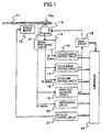
- FIG. 1 is a block diagram illustrating a constitution of an optical disk apparatus of the present invention, which reproduces a multi-layer recording optical disk.
- the optical disk apparatus includes a spindle motor 12, an optical pickup 13, a signal processing circuit 14, a drive circuit 15, a tracking servo control circuit 16, a focus servo control circuit 17, a layer-jump control circuit 18, a sensitivity adjusting circuit 19, reproducing circuit 20, a rotation control circuit 21, and a controller 22.
- description of a mechanism, a control circuit and the like for moving the optical pickup 13 in a tracking direction is omitted in order to mainly explain a control of movement of the optical pickup 13 in a focusing direction.
- This optical disk apparatus rotates an optical disk 11, such as a DVD-ROM having a multi-layer recording structure by use of the spindle motor 12, based on a rotational speed control signal from the rotation control circuit 21. Then a laser beam is emitted from the optical pickup 13 and converged on a recording layer of the optical disk 11 by the objective lens 13a. The light reflected on the recording layer is read by the optical pickup 13 (scanning). An optical signal read is converted to electric signals such as a tracking error signal (TE signal), a focus error signal (FE signal) and a reflected light quantity signal (RF signal) in the signal processing circuit 14.
- TE signal tracking error signal
- FE signal focus error signal
- RF signal reflected light quantity signal
- the FE signal, the RF signal and the TE signal can be generated, for example, by providing an optical detecting element divided into four parts in a light receiving unit of the optical pickup 13 and amplifying a difference or a sum of outputs of the upper and lower, or the left and right parts of the optical detecting element by use of an astigmatism method.
- the optical pickup 13 is provided with an actuator 21 for driving the objective lens 13a in the focusing direction and in the tracking direction (in the radial direction of the optical disk 11).
- the actuator 21 is independently controlled with respect to the focusing direction and the tracking direction by a control signal from the drive circuit 15.
- the TE signal is inputted to the tracking servo control circuit 16.
- the tracking servo control circuit 16 generates a signal for driving the actuator 21 in the tracking direction based on the TE signal so that a laser beam may follow a track deflection, and outputs the generated signal to the drive circuit 15.
- the FE signal is inputted to the focus servo control circuit 17 and the layer-jump control circuit 18.
- the focus servo control circuit 17 generates a signal for driving the actuator 21 in the focusing direction based on the FE signal so that a laser beam passing through the objective lens 13a may be converged on the recording layer of the optical disk 11, and outputs the generated signal for driving the actuator 21 to the drive circuit 15.
- the layer-jump control circuit 18 makes the drive circuit 15 generate a kick voltage for moving a focal point of the objective lens 13a to a target layer.
- the layer-jump control circuit 18 monitors the FE signal, and makes the drive circuit 15 generate a brake voltage for stopping movement of the objective lens 13a on detecting the focal point of the objective lens 13a coming close to the target layer.
- the signals (the kick signal and the brake signal) generated by the drive circuit 15 may be signals determined in accordance with electric current or the like as well as the voltage signal.
- the RF signal is inputted into the sensitivity adjusting circuit 19 and the reproducing circuit 20.
- the sensitivity adjusting circuit 19 detects the RF signals from the surface and the recording layer of the optical disk 11 by moving the objective lens 13a in the focusing direction, and measures the sensitivity of the actuator 21. In accordance with the measured sensitivity, the sensitivity adjusting circuit 19 adjusts the kick voltage and the brake voltage to be applied to a coil of the actuator 21 by the drive circuit 15 during layer jumping.
- the reproducing circuit 20 conducts a predetermined demodulation and then an error correction for data read in accordance with the RF signal.
- the digital signal obtained is subjected to a process such as analog conversion to reproduce audio data, video data or the like.
- the controller 22 of the optical disk apparatus controls each process, described above, in the drive circuit 15, the tracking servo control circuit 16, the focus servo control circuit 17, the layer-jump control circuit 18, the sensitivity adjusting circuit 19, the reproducing circuit 20, or the rotation control circuit 21.
- the controller 22 receives the demand for layer jumping through the control signal from the reproducing circuit 20 while reproducing the optical disk 11, the controller 22 sends a command for switching the focus servo to the OFF status to the focus servo control circuit 17 and also sends a command for layer jumping to the layer-jump control circuit 18.
- the controller 22 Upon termination of layer jumping from the layer-jump control circuit 18, the controller 22 sends a command for switching the focus servo to the ON status to the focus servo control circuit 17 and restarts reading the data of the optical disk 11 by use of the reproducing circuit 20.
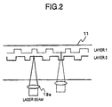
- the multi-layer recording optical disk 11 has, as shown in FIG. 2, a two-layer structure with two recording layers.
- a layer close to the objective lens 13a is called a layer 0, and a layer far from the objective lens 13a is called a layer 1 in the two recording layers.
- the recording layer represented by a solid line is the layer 0, and the recording layer represented by a dashed line is the layer 1.
- the external dimensions of the multi-layer recording optical disk are, for example, set to have a diameter of 120 mm and a thickness of 1.2 mm like the CD-ROM.
- the DVD-ROM has a structure, in which two disks, each having a thickness of 0.6 mm, are laminated with each other. Two layers are recordable at a maximum on each surface.
- the storage capacity is 4.7 GB in recording on one layer on one surface; 8.5 GB in recording on two layers on one surface; 9.4 GB in recording on one layer on both surface; and 17 GB in recording on two layers on both surface.
- the track pitch is 0.74 ⁇ m and the wavelength of a data reading laser beam is 650 nm.
- the optical disk apparatus of the present invention can reproduce another optical disk having three or more layers. Further, the optical disk apparatus can reproduce the CD-ROM or the like, which are different from the DVD-ROM in the track pitch, the wave length of the data-reading laser beam, an encoding method, or the like.
- a substrate of the optical disk 11 mainly employs polycarbonate resin, which is high in optical transmissivity and has characteristics of high impact resistance, high heat resistance, and high moisture proof.
- a reflective film by depositing aluminum or the like.
- the reflectivity of the reflective film is, for example, approximately 80%.
- the reflective film is also provided with a protective film made from polycarbonate resin thereon.
- the surface of the signal reading side of the optical disk 11 has, for example, a reflectivity of approximately 4%. Accordingly, the RF signal, which is obtained from the optical disk 11 when the optical pickup 13 is moved in the focusing direction, is amplified and observed, so that a small peak of the reflected light in the case when the surface of the optical disk 11 is in focus and a large peak of the reflected light in the case when the recording layer is in focus can be distinctively detected.
- the optical pickup 13 reads the data from the optical disk 11.
- An optical system of the optical pickup 13 includes, for example, as shown in FIG. 3, the objective lens 13a, a collimating lens 13b, a polarizing prism 13c, a semiconductor laser oscillator 13d, a cylindrical lens 13e, and an optical detecting element 13f.
- the laser beam emitted from the semiconductor laser oscillator 13d travels straight in the polarizing prism 13c, passed through the collimating lens 13b, and converged on any one of the recording layers of the optical disk 11 by the objective lens 13a.
- the reflected light from the optical disk 11 travels back in the objective lens 13a, and is passed through the collimating lens 13b. Thereafter, the reflected light is bent at a right angle by the polarizing prism 13c, and is made incident into the optical detecting element 13f through a cylindrical lens 13e.
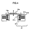
- FIG. 4 is a diagram illustrating a mechanism in which the objective lens 13a is driven in the focusing direction by the actuator 21.
- the objective lens 13a is supported by objective lens supporting springs 21c through an objective lens holder 13g so as to be displaced vertically and horizontally.
- the circumference of the objective lens 13a is provided with a coil 21a for focusing.
- magnets 21b are provided on the outside of the coil 21a for focusing.
- FIG. 5 is a diagram illustrating an example of a waveform of an FE signal while the objective lens 13a is moved close to the optical disk 11 from a distant position.
- a layer 0 focusing point indicated by an arrow shows a position of a focusing point of the layer close to the objective lens 13a (layer 0)
- a layer 1 focusing point shows a position of a focusing point of the layer far from the objective lens 13a (layer 1).
- Hi and Lo show upward and downward directions with reference to FE signal voltage 0.
- the FE signal first forms a peak in the Hi direction when the objective lens 13a is started to move from a distant position toward the optical disk 11, and reaches a reference level at a position, thus providing the focusing point of the layer 0 in the vicinity thereof. Thereafter, the FE signal forms a peak in the Lo direction and passes again through the reference level to form a peak in the Hi direction. Then the FE signal reaches the reference level again at a position, thus providing the focusing point of the layer 1 in the vicinity thereof. When the objective lens 13a is moved further close to the optical disk, the FE signal again forms a peak in the Lo direction.
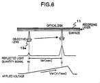
- FIG. 6 is a diagram schematically illustrating a relation among the position of the objective lens 13a when being moved in the focusing direction at a low speed, the RF signal, and the voltage to be applied to the coil 21a for focusing of the actuator 21.
- the RF signal forms a small peak when a focal point of the objective lens 13a reaches the surface of the optical disk 11. Such time is represented by t s .
- t r Such time is represented by t r .
- a time period between t s and t r is a time period t sr between the refection on the surface and the reflection on the recording layer.
- the parameters except t sr [s] may be substantially fixed.
- the high speed sensitivity of the actuator 21 is considered to be a value in accordance with t sr , which is obtained when the objective lens 13a is moved at a low speed.
- a dispersion of the high speed sensitivity of the actuator 21 can be determined as a dispersion of the time period t sr between the reflection on the surface and the reflection of the recording layer.
- a high speed sensitivity of the actuator 21 causes a problem during layer jumping, in which the objective lens 13a is moved at a high speed.
- the objective lens 13a prior to reproducing an optical disk, for instance, in insertion of an optical disk, in receiving a start command of reproduction from users, or in first insertion of an optical disk after a power is turned on, the objective lens 13a is moved in the focusing direction at a low speed.
- the sensitivity adjusting circuit 19, as previously described, measures the time period t sr [sec] between the reflection on the surface and the reflection on the recording layer based on the RF signal from the optical disk 11.
- an optical disk apparatus capable of reproducing the DVD-ROM and the CD-ROM may use the time period t sr between the reflection on the surface and the reflection on the recording layer to discriminate the kind of disk media.
- the DVD-ROM and the CD-ROM have the same thickness of 1.2 mm, but have a difference in the distance between the surface and the recording layer of the optical disk. In some types of the optical disk apparatus, such difference is used to measure t sr when the optical disk is inserted or at other time. The optical disk apparatus judges that the inserted disk medium is the CD-ROM if t sr is not less than a predetermined value; otherwise the inserted disk medium is the DVD-ROM.
- the sensitivity adjusting of the actuator 21 can be conducted based on t sr measured in the process of discrimination of the disk media.
- the drive circuit 15 applies the kick voltage and the brake voltage to the coil 21a for focusing of the actuator 21 so as to move the objective lens 13a by a distance of the recording layers during layer jumping.
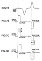
- FIG. 7A shows an FE signal during layer jumping;
- FIGs. 7B to 7D are diagrams, each showing a voltage applied to the coil 21a for focusing.
- the layer-jump control circuit 18 makes the drive circuit 15 generate a kick pulse to start movement of the objective lens 13a. Then the layer-jump control circuit 18 monitors the FE signal. On detecting the FE signal which has reached a predetermined value, the layer-jump control circuit 18 makes the drive circuit 15 generate a brake pulse of an opposite polarity to that of the kick pulse, and stops movement of the objective lens 13a.
- each of the kick pulse and the brake pulse has a predetermined voltage value and a predetermined pulse width.
- a drive force and a brake force to be applied to the objective lens 13a can be adjusted.
- the sensitivity adjusting of the actuator 21 can be conducted by changing the voltage value and the pulse width based on t sr measured.
- FIG. 7C illustrates an example in which the sensitivity is adjusted by changing the voltage value of the pulse. If t sr measured is relatively small, the sensitivity of the actuator 21 is adjusted by decreasing the pulse voltage. On the other hand, if t sr measured is relatively large, the sensitivity of the actuator 21 is adjusted by increasing the pulse voltage.
- the sensitivity adjusting circuit 19 stores an average time period t std [sec] between the reflection on the surface and the reflection on the recording layer, and an average pulse voltage value V std [V] in advance. For instance, such average values can be calculated experimentally or theoretically.
- V h V std ⁇ t sr / t std [V]
- V h V std ⁇ t sr / t std [V]
- the drive circuit 15 receives a command for applying the kick voltage and the brake voltage from the layer-jump control circuit 18, the pulse voltage of V h [V] is applied to the coil 21a for focusing of the actuator 21. Accordingly, the objective lens 13a is controlled in accordance with the sensitivity of the actuator 21, so that layer jumping in which the sensitivity dispersion has been adjusted can be conducted.
- V h ⁇ + (V std - ⁇ ) ⁇ t sr / t std [V]
- FIG. 7D shows an example in which the sensitivity adjustment is made by changing the pulse width (time period of applying a voltage). If t sr measured is relatively small, the sensitivity of the actuator 21 is adjusted by decreasing the pulse width, On the other hand, if t sr measured is relatively large, the sensitivity of the actuator 21 is adjusted by increasing the pulse width.
- the sensitivity adjusting circuit 19 stores an average time period t std [sec] between the reflection on the surface and the reflection on the recording layer, and an average pulse width P std [sec] in advance. For instance, such average values can be calculated experimentally or theoretically.
- the drive circuit 15 receives a command for applying the kick voltage and the brake voltage from the layer-jump control circuit 18, this pulse voltage having a width of P w [sec] is applied to the coil 21a for focusing of the actuator 21. Accordingly, the objective lens 13a is controlled in accordance with the sensitivity of the actuator 21, so that layer jumping in which the sensitivity dispersion has been adjusted can be conducted.
- P w ⁇ + (P std - ⁇ ) ⁇ t sr / t std [sec]
- the pulse voltage value V h [V] and the pulse width P w [sec] are proper values in accordance with t sr are not necessary to be defined by the formula. Such values in accordance with t sr may be selected among a plurality of predetermined values by using tables or the like.
- Both of the voltage value and the width of the pulse can be changed. Even when a voltage to be applied to the coil of the actuator 21 is not shaped in a pulse waveform, the present invention can be applied to the optical disk apparatus. In other words, it is necessary only that an integral value of a voltage to be applied is in accordance with t sr measured. For instance, when a voltage having a triangle waveform is applied to the coil, the integral value of the voltage can be adjusted by changing a height or a width of the triangle waveform. Furthermore, the voltage value, the pulse width, and the like are calculated by use of the parameters different in the kick voltage and the brake voltage by considering the characteristics of the actuator, the gravity direction and the like.
- Each process of the above optical disk apparatus can be controlled based on, for example, programs such as a driver, firmware, or the like.
- programs can be stored in a storage unit equipped in the optical disk apparatus.
- a program for control can be stored in a recording medium such as an optical disk and read into the optical disk apparatus when necessary.
- the layer jumping control according to the present invention can, of course, be applied to an optical disk with a structure of three layers or more as well as an optical disk with a two-layer structure. Moreover, the layer jumping control can be applied to not only a reproducing apparatus but also a recording apparatus.
- the sensitivity dispersion of the actuator of the optical pickup during layer jumping can be adjusted.
Landscapes
- Moving Of The Head For Recording And Reproducing By Optical Means (AREA)
- Optical Recording Or Reproduction (AREA)
Abstract
Description
Claims (13)
- A method of controlling movement of an objective lens in an optical disk apparatus, comprising the steps of
measuring a time for moving a focal point of said objective lens between a surface and a recording layer of an optical disk by moving said objective lens for converging a laser beam in a focusing direction to observe a reflected light from said optical disk while emitting said laser beam to said optical disk; and
moving said objective lens by use of a first signal for driving said objective lens toward a recording layer on which the laser beam is to be converged and a second signal for braking said objective lens, when the recording layer on which the laser beam is to be converged is required to be changed at the time of scanning a multi-layer recording optical disk, said first and second signals being separately defined based on a ratio of said measured time and a predetermined reference time. - The method of controlling movement of an objective lens according to claim 1, wherein said first signal and said second signal are represented by pulse voltage and the value of the pulse voltage is determined in accordance with the ratio of said measured time to the predetermined reference time.
- The method of controlling movement of an objective lens according to claim 1, wherein said first signal and said second signal are represented by pulse voltage and the width of the pulse voltage is determined in accordance with the ratio of said measured time to the predetermined reference time.
- The method of controlling movement of an objective lens according to claim 1, wherein the time for moving a focal point of said objective lens between the surface and the recording layer of the optical disk is measured in a process of identifying a kind of the optical disk.
- The method of controlling movement of an objective lens according to claim 2, wherein the time for moving a focal point of said objective lens between the surface and the recording layer of the optical disk is measured in a process of identifying a kind of the optical disk.
- The method of controlling movement of an objective lens according to claim 3, wherein the time for moving a focal point of said objective lens between the surface and the recording layer of the optical disk is measured in a process of identifying a kind of the optical disk.
- An optical disk apparatus of driving a multi-layer recording optical disk, comprising:means of measuring a time for moving a focal point of an objective lens between a surface and a recording layer of an optical disk by moving said objective lens for converging a laser beam in a focusing direction to observe a reflected light from said optical disk while emitting said laser beam to said optical disk; andcontrolling means for moving said objective lens by use of a first signal for driving said objective lens toward a recording layer on which the laser beam is to be converged and a second signal for braking said objective lens, when the recording layer on which the laser beam is to be converged is required to be changed at the time of scanning the optical disk, said first and second signals being separately defined based on a ratio of said measured time and a predetermined reference time.
- The optical disk apparatus according to claim 7, wherein said first signal and said second signal are represented by pulse voltage and the value of the pulse voltage is determined in accordance with the ratio of said measured time to the predetermined reference time.
- The optical disk apparatus according to claim 7, wherein said first signal and said second are represented by pulse voltage and the width of the pulse voltage is determined in accordance with the ratio of said measured time to the predetermined reference time.
- The optical disk apparatus according to claim 7, further comprising:means for reproducing a plurality of optical disk media different in standard, whereinthe time for moving a focal point of said objective lens between the surface and the recording layer of the optical disk is measured in a process of identifying a kind of the optical disk.
- The optical disk apparatus according to claim 8, further comprising:means for reproducing a plurality of optical disk media different in standard, whereinthe time for moving a focal point of said objective lens between the surface and the recording layer of the optical disk is measured in a process of identifying a kind of the optical disk.
- The optical disk apparatus according to any one of claims 9, further comprising:means for reproducing a plurality of optical disk media different in standard, whereinthe time for moving a focal point of said objective lens between the surface and the recording layer of the optical disk is measured in a process of identifying a kind of the optical disk.
- A recording medium having a program recorded thereon for controlling an optical disk apparatus driving a multi-layer recording optical disk, the program causing the optical disk apparatus to conduct:a procedure of measuring a time for moving a focal point of an objective lens between a surface and a recording layer of an optical disk by moving said objective lens for converging a laser beam in a focusing direction to observe a reflected light from said optical disk while emitting said laser beam to said optical disk; anda control procedure of movement of an objective lens for moving said objective lens by use of a first signal for driving said objective lens toward a recording layer on which the laser beam is to be converged and a second signal for braking said objective lens, when the recording layer on which the laser beam is to be converged is required to be changed at the time of scanning the optical disk, said first and second signals being separately defined based on a ratio of said measured time and a predetermined reference time.
Applications Claiming Priority (4)
| Application Number | Priority Date | Filing Date | Title |
|---|---|---|---|
| JP2001003903 | 2001-01-11 | ||
| JP2001003903 | 2001-01-11 | ||
| JP2002000786 | 2002-01-07 | ||
| JP2002000786A JP2002279654A (en) | 2001-01-11 | 2002-01-07 | Optical disk apparatus and method for controlling movement of objective lens |
Publications (2)
| Publication Number | Publication Date |
|---|---|
| EP1225572A1 true EP1225572A1 (en) | 2002-07-24 |
| EP1225572B1 EP1225572B1 (en) | 2003-11-19 |
Family
ID=26607546
Family Applications (1)
| Application Number | Title | Priority Date | Filing Date |
|---|---|---|---|
| EP02000218A Expired - Lifetime EP1225572B1 (en) | 2001-01-11 | 2002-01-11 | Optical disk apparatus and method of controlling movement of objective lens |
Country Status (7)
| Country | Link |
|---|---|
| US (1) | US6775209B2 (en) |
| EP (1) | EP1225572B1 (en) |
| JP (1) | JP2002279654A (en) |
| KR (1) | KR100816972B1 (en) |
| CN (1) | CN1220184C (en) |
| DE (1) | DE60200092T2 (en) |
| ES (1) | ES2211830T3 (en) |
Cited By (1)
| Publication number | Priority date | Publication date | Assignee | Title |
|---|---|---|---|---|
| EP1884941A1 (en) * | 2006-07-31 | 2008-02-06 | Funai Electric Co., Ltd. | Information reproducing/recording device |
Families Citing this family (19)
| Publication number | Priority date | Publication date | Assignee | Title |
|---|---|---|---|---|
| CN1299271C (en) * | 2001-07-26 | 2007-02-07 | 索尼株式会社 | Optical disc recording/reproducing device, focusing method thereof |
| JP4109018B2 (en) * | 2002-05-27 | 2008-06-25 | パイオニア株式会社 | Actuator |
| KR20040044846A (en) * | 2002-11-22 | 2004-05-31 | 삼성전자주식회사 | Method for discriminating type of disc in the disc drive and apparatus thereof |
| JP4142972B2 (en) * | 2003-02-25 | 2008-09-03 | 株式会社リコー | POSITION CONTROL METHOD, PROGRAM AND RECORDING MEDIUM, POSITION CONTROL DEVICE, AND OPTICAL DISK DEVICE |
| US7092344B2 (en) * | 2003-04-18 | 2006-08-15 | Lucere Enterprises, Ltd. | Apparatus for creating a multi-dimensional data signal |
| US20050052982A1 (en) * | 2003-09-09 | 2005-03-10 | Lucere, Lp | Virtual head for generating a multi-dimensional data signal |
| US7149169B2 (en) * | 2003-11-13 | 2006-12-12 | Mediatek Inc. | Distinguishing optical disc types |
| JP2007525786A (en) * | 2004-03-01 | 2007-09-06 | アリマ デバイシズ コーポレイション | Apparatus for reading / writing multi-layer optical discs with improved layer jump |
| JP3992044B2 (en) * | 2004-04-22 | 2007-10-17 | ソニー株式会社 | Playback device, focus jump method |
| TWI271724B (en) * | 2004-05-21 | 2007-01-21 | Realtek Semiconductor Corp | Apparatus and method for layer jump braking control in optical drive |
| US7514661B2 (en) * | 2005-01-04 | 2009-04-07 | Hewlett-Packard Development Company, L.P. | Focus calibration in an optical drive |
| JP2006277777A (en) | 2005-03-02 | 2006-10-12 | Sony Corp | Playback device and layer jump method |
| JP3971427B2 (en) * | 2005-03-02 | 2007-09-05 | 株式会社ソニー・コンピュータエンタテインメント | Optical disc drive apparatus, optical disc drive apparatus control method, and control program |
| US8149665B2 (en) * | 2005-03-09 | 2012-04-03 | Mitsubishi Electric Corporation | Optical disc device |
| KR20080071806A (en) * | 2007-01-31 | 2008-08-05 | 삼성전자주식회사 | Focus control method and apparatus for optical information storage medium reproducing / recording device |
| KR101307541B1 (en) * | 2007-02-14 | 2013-09-12 | 삼성전자주식회사 | Method for controlling focus of optical information storing media and apparatus thereof |
| KR100926178B1 (en) * | 2008-10-08 | 2009-11-10 | 은강정보통신(주) | Laser floodlight |
| JP6097164B2 (en) * | 2013-07-05 | 2017-03-15 | クラリオン株式会社 | Optical pickup control device and optical disk device |
| WO2015098321A1 (en) * | 2013-12-24 | 2015-07-02 | ソニー株式会社 | Control device, control method, and program |
Citations (5)
| Publication number | Priority date | Publication date | Assignee | Title |
|---|---|---|---|---|
| EP0807926A1 (en) * | 1996-05-15 | 1997-11-19 | Pioneer Electronic Corporation | Multiple layer disk reproducing apparatus, and apparatus for reproducing information record medium |
| JPH1139663A (en) * | 1997-07-15 | 1999-02-12 | Pioneer Electron Corp | Focus controller for multilayer optical recording medium |
| US5903530A (en) * | 1996-06-11 | 1999-05-11 | Pioneer Electronic Corporation | Apparatus for reproducing record information of multiple-layered optical disc |
| EP0919994A2 (en) * | 1997-11-28 | 1999-06-02 | Pioneer Electronic Corporation | Transfer control system of information read beam |
| US6147942A (en) * | 1997-07-15 | 2000-11-14 | Pioneer Corporation | Focus control apparatus for multilayer optical recording medium |
Family Cites Families (8)
| Publication number | Priority date | Publication date | Assignee | Title |
|---|---|---|---|---|
| JP2586206B2 (en) * | 1990-11-09 | 1997-02-26 | 三菱電機株式会社 | Disk drive |
| JP3561576B2 (en) * | 1995-09-07 | 2004-09-02 | パイオニア株式会社 | Multi-layer disc playback device |
| KR0183172B1 (en) * | 1995-09-30 | 1999-04-15 | 김광호 | Dual layer disk focusing apparatus and method thereof |
| US6327120B1 (en) * | 1997-04-17 | 2001-12-04 | Fujitsu Limited | Actuator using piezoelectric element and head-positioning mechanism using the actuator |
| EP1262962A3 (en) * | 1997-10-16 | 2004-10-27 | Sony Corporation | Optical disc apparatus having collision preventing means and method for controlling an optical disc apparatus |
| JP3890709B2 (en) | 1997-11-17 | 2007-03-07 | ソニー株式会社 | Optical recording medium driving apparatus and optical recording medium discrimination method |
| JP2000173065A (en) | 1998-12-02 | 2000-06-23 | Sony Corp | Optical disk player device and sensitivity detection method for focus servo mechanism |
| JP3726621B2 (en) * | 2000-02-25 | 2005-12-14 | 三菱電機株式会社 | Focus pull-in method and optical disk apparatus |
-
2002
- 2002-01-07 JP JP2002000786A patent/JP2002279654A/en active Pending
- 2002-01-11 ES ES02000218T patent/ES2211830T3/en not_active Expired - Lifetime
- 2002-01-11 CN CNB021009899A patent/CN1220184C/en not_active Expired - Lifetime
- 2002-01-11 EP EP02000218A patent/EP1225572B1/en not_active Expired - Lifetime
- 2002-01-11 KR KR1020020001664A patent/KR100816972B1/en not_active Expired - Lifetime
- 2002-01-11 DE DE60200092T patent/DE60200092T2/en not_active Expired - Lifetime
- 2002-01-11 US US10/043,661 patent/US6775209B2/en not_active Expired - Lifetime
Patent Citations (5)
| Publication number | Priority date | Publication date | Assignee | Title |
|---|---|---|---|---|
| EP0807926A1 (en) * | 1996-05-15 | 1997-11-19 | Pioneer Electronic Corporation | Multiple layer disk reproducing apparatus, and apparatus for reproducing information record medium |
| US5903530A (en) * | 1996-06-11 | 1999-05-11 | Pioneer Electronic Corporation | Apparatus for reproducing record information of multiple-layered optical disc |
| JPH1139663A (en) * | 1997-07-15 | 1999-02-12 | Pioneer Electron Corp | Focus controller for multilayer optical recording medium |
| US6147942A (en) * | 1997-07-15 | 2000-11-14 | Pioneer Corporation | Focus control apparatus for multilayer optical recording medium |
| EP0919994A2 (en) * | 1997-11-28 | 1999-06-02 | Pioneer Electronic Corporation | Transfer control system of information read beam |
Non-Patent Citations (1)
| Title |
|---|
| PATENT ABSTRACTS OF JAPAN vol. 1999, no. 05 31 May 1999 (1999-05-31) * |
Cited By (1)
| Publication number | Priority date | Publication date | Assignee | Title |
|---|---|---|---|---|
| EP1884941A1 (en) * | 2006-07-31 | 2008-02-06 | Funai Electric Co., Ltd. | Information reproducing/recording device |
Also Published As
| Publication number | Publication date |
|---|---|
| CN1220184C (en) | 2005-09-21 |
| US20020089912A1 (en) | 2002-07-11 |
| CN1366301A (en) | 2002-08-28 |
| KR100816972B1 (en) | 2008-03-25 |
| ES2211830T3 (en) | 2004-07-16 |
| DE60200092T2 (en) | 2004-07-22 |
| JP2002279654A (en) | 2002-09-27 |
| DE60200092D1 (en) | 2003-12-24 |
| US6775209B2 (en) | 2004-08-10 |
| KR20020060622A (en) | 2002-07-18 |
| EP1225572B1 (en) | 2003-11-19 |
Similar Documents
| Publication | Publication Date | Title |
|---|---|---|
| EP1225572B1 (en) | Optical disk apparatus and method of controlling movement of objective lens | |
| JP2728065B2 (en) | Optical disc automatic discrimination method and system | |
| EP1521246A1 (en) | Optical recording/reproduction device and focal point control method | |
| TWI221278B (en) | Method and apparatus for controlling movement of objective lens | |
| JP2001319344A (en) | Focus controller, recording medium and optical disk reproducing device | |
| US6134196A (en) | Carriage controller for multi-layer disc | |
| JP2003099970A (en) | Optical disc device and focus control method | |
| US7061835B2 (en) | Method and apparatus for focus control of lens for reading multilayer optical medium | |
| EP1998330B1 (en) | Discrimination method for optical disc types and optical disc apparatus | |
| US7773488B2 (en) | Information reproducing apparatus | |
| JPWO1997033276A1 (en) | Focusing device and optical disc device using same | |
| JP3611426B2 (en) | Focus control device for multilayer optical recording medium | |
| JP3975573B2 (en) | Recording medium reproducing apparatus and recording medium reproducing method | |
| JP2882383B2 (en) | Optical disk recording and playback device | |
| WO2004044906A1 (en) | Optical disk drive device and method of correcting tilt of optical pickup | |
| JPH10149614A (en) | Optical disk drive | |
| JP2010079945A (en) | Optical disk recording and reproducing device, and method of correcting temperature characteristic of optical pickup of optical disk recording and reproducing device | |
| JP4221729B2 (en) | Recording medium playback device | |
| JP2000251383A5 (en) | Disk drive device, recording layer identification method | |
| JPH11120569A (en) | Optical disk recording and reproducing apparatus and method | |
| JP2000200430A (en) | Optical disk device | |
| JP2004103234A (en) | Optical disk apparatus and optical disk processing method | |
| JP2000293867A (en) | Focus control method for surface writing type optical recording device | |
| JPH0944892A (en) | Recording and / or reproducing apparatus for optical recording medium | |
| JP2002324331A (en) | Optical disc focus control method and optical disc apparatus |
Legal Events
| Date | Code | Title | Description |
|---|---|---|---|
| PUAI | Public reference made under article 153(3) epc to a published international application that has entered the european phase |
Free format text: ORIGINAL CODE: 0009012 |
|
| AK | Designated contracting states |
Kind code of ref document: A1 Designated state(s): AT BE CH CY DE DK ES FI FR GB GR IE IT LI LU MC NL PT SE TR |
|
| AX | Request for extension of the european patent |
Free format text: AL;LT;LV;MK;RO;SI |
|
| 17P | Request for examination filed |
Effective date: 20030114 |
|
| AKX | Designation fees paid |
Designated state(s): DE ES FR GB IT |
|
| GRAH | Despatch of communication of intention to grant a patent |
Free format text: ORIGINAL CODE: EPIDOS IGRA |
|
| GRAS | Grant fee paid |
Free format text: ORIGINAL CODE: EPIDOSNIGR3 |
|
| GRAA | (expected) grant |
Free format text: ORIGINAL CODE: 0009210 |
|
| AK | Designated contracting states |
Kind code of ref document: B1 Designated state(s): DE ES FR GB IT |
|
| REG | Reference to a national code |
Ref country code: GB Ref legal event code: FG4D |
|
| REF | Corresponds to: |
Ref document number: 60200092 Country of ref document: DE Date of ref document: 20031224 Kind code of ref document: P |
|
| REG | Reference to a national code |
Ref country code: IE Ref legal event code: FG4D |
|
| REG | Reference to a national code |
Ref country code: ES Ref legal event code: FG2A Ref document number: 2211830 Country of ref document: ES Kind code of ref document: T3 |
|
| ET | Fr: translation filed | ||
| PLBE | No opposition filed within time limit |
Free format text: ORIGINAL CODE: 0009261 |
|
| STAA | Information on the status of an ep patent application or granted ep patent |
Free format text: STATUS: NO OPPOSITION FILED WITHIN TIME LIMIT |
|
| REG | Reference to a national code |
Ref country code: IE Ref legal event code: MM4A |
|
| 26N | No opposition filed |
Effective date: 20040820 |
|
| REG | Reference to a national code |
Ref country code: FR Ref legal event code: PLFP Year of fee payment: 15 |
|
| REG | Reference to a national code |
Ref country code: FR Ref legal event code: PLFP Year of fee payment: 16 |
|
| REG | Reference to a national code |
Ref country code: FR Ref legal event code: PLFP Year of fee payment: 17 |
|
| PGFP | Annual fee paid to national office [announced via postgrant information from national office to epo] |
Ref country code: FR Payment date: 20201210 Year of fee payment: 20 Ref country code: GB Payment date: 20201230 Year of fee payment: 20 |
|
| PGFP | Annual fee paid to national office [announced via postgrant information from national office to epo] |
Ref country code: DE Payment date: 20201229 Year of fee payment: 20 Ref country code: ES Payment date: 20210203 Year of fee payment: 20 |
|
| PGFP | Annual fee paid to national office [announced via postgrant information from national office to epo] |
Ref country code: IT Payment date: 20201211 Year of fee payment: 20 |
|
| REG | Reference to a national code |
Ref country code: DE Ref legal event code: R071 Ref document number: 60200092 Country of ref document: DE |
|
| REG | Reference to a national code |
Ref country code: GB Ref legal event code: PE20 Expiry date: 20220110 |
|
| REG | Reference to a national code |
Ref country code: ES Ref legal event code: FD2A Effective date: 20220426 |
|
| PG25 | Lapsed in a contracting state [announced via postgrant information from national office to epo] |
Ref country code: GB Free format text: LAPSE BECAUSE OF EXPIRATION OF PROTECTION Effective date: 20220110 |
|
| PG25 | Lapsed in a contracting state [announced via postgrant information from national office to epo] |
Ref country code: ES Free format text: LAPSE BECAUSE OF EXPIRATION OF PROTECTION Effective date: 20220112 |