EP1225426B1 - A non-contact linear position sensor - Google Patents
A non-contact linear position sensor Download PDFInfo
- Publication number
- EP1225426B1 EP1225426B1 EP02250199A EP02250199A EP1225426B1 EP 1225426 B1 EP1225426 B1 EP 1225426B1 EP 02250199 A EP02250199 A EP 02250199A EP 02250199 A EP02250199 A EP 02250199A EP 1225426 B1 EP1225426 B1 EP 1225426B1
- Authority
- EP
- European Patent Office
- Prior art keywords
- pattern
- coupler
- section
- position sensor
- receive
- Prior art date
- Legal status (The legal status is an assumption and is not a legal conclusion. Google has not performed a legal analysis and makes no representation as to the accuracy of the status listed.)
- Expired - Lifetime
Links
Images


Classifications
-
- G—PHYSICS
- G01—MEASURING; TESTING
- G01D—MEASURING NOT SPECIALLY ADAPTED FOR A SPECIFIC VARIABLE; ARRANGEMENTS FOR MEASURING TWO OR MORE VARIABLES NOT COVERED IN A SINGLE OTHER SUBCLASS; TARIFF METERING APPARATUS; MEASURING OR TESTING NOT OTHERWISE PROVIDED FOR
- G01D5/00—Mechanical means for transferring the output of a sensing member; Means for converting the output of a sensing member to another variable where the form or nature of the sensing member does not constrain the means for converting; Transducers not specially adapted for a specific variable
- G01D5/12—Mechanical means for transferring the output of a sensing member; Means for converting the output of a sensing member to another variable where the form or nature of the sensing member does not constrain the means for converting; Transducers not specially adapted for a specific variable using electric or magnetic means
- G01D5/14—Mechanical means for transferring the output of a sensing member; Means for converting the output of a sensing member to another variable where the form or nature of the sensing member does not constrain the means for converting; Transducers not specially adapted for a specific variable using electric or magnetic means influencing the magnitude of a current or voltage
- G01D5/20—Mechanical means for transferring the output of a sensing member; Means for converting the output of a sensing member to another variable where the form or nature of the sensing member does not constrain the means for converting; Transducers not specially adapted for a specific variable using electric or magnetic means influencing the magnitude of a current or voltage by varying inductance, e.g. by a movable armature
- G01D5/204—Mechanical means for transferring the output of a sensing member; Means for converting the output of a sensing member to another variable where the form or nature of the sensing member does not constrain the means for converting; Transducers not specially adapted for a specific variable using electric or magnetic means influencing the magnitude of a current or voltage by varying inductance, e.g. by a movable armature by influencing the mutual induction between two or more coils
- G01D5/2053—Mechanical means for transferring the output of a sensing member; Means for converting the output of a sensing member to another variable where the form or nature of the sensing member does not constrain the means for converting; Transducers not specially adapted for a specific variable using electric or magnetic means influencing the magnitude of a current or voltage by varying inductance, e.g. by a movable armature by influencing the mutual induction between two or more coils by a movable non-ferromagnetic conductive element
Landscapes
- Physics & Mathematics (AREA)
- General Physics & Mathematics (AREA)
- Measurement Of Length, Angles, Or The Like Using Electric Or Magnetic Means (AREA)
- Transmission And Conversion Of Sensor Element Output (AREA)
- Near-Field Transmission Systems (AREA)
Description
- The present invention is directed to a non-contact linear position sensor for motion control applications, and is related to the invention disclosed in our U.S. Patent No. 6,304,076.
- In order to meet the current stringent reliability and meantime before failure (MTBF) requirements demanded by the automotive, industrial and aerospace industries, position sensors must be based on a non-contact design approach. For automotive use, the design must be suited for low cost, high volume, and high reliability. US Patent No. 6,304,076 discloses and claims an angular position sensor which is useful, for example, in the automotive field for determining the rotation of a steering column. This same type of non-contacting position sensor can also be adapted to measure the torque in a steering column as disclosed in our co-pending application, Serial No. 09/527,088, filed March 16, 2000, entitled, NON-CONTACTING TORQUE SENSOR and assigned to the present Assignee. However, there is still a need for a linear position sensor, for example, one that may be used with a voice-coil actuator in order to provide built-in feedback control for motion control applications.
- US 4,697,144 describes a position sensing apparatus in which an unenergized member moves relative to an energized primary core system and a secondary core system. The unenergized member acts as a flux-coupler between the two core systems.
- US 4,737, 698 describes a sensor with an excitation winding and a secondary winding together with a conductive screen within which eddy currents are generated in the presence of a drive field, which is detected by the secondary winding.
- It is therefore a general object of the present invention to provide a non-contact linear position sensor for motion control applications.
- In accordance with the above object there is provided a non-contact linear position sensor, as defined by
claim 1. - The position sensor for sensing rectilinear movement of an object along an axis comprises a pair of spaced substantially rectilinear radio transmit and receive sections juxtaposed on the axis facing each other with a coupler section between then, the coupler being movable along the axis and connected to the object. The receive section carries a predetermined number of independent inductive coils segmentally arranged in a rectilinear pattern along the receive section. The transmit section carries coil means in a rectilinear pattern similar to the receive section and is driven by a signal source at a predetermined radio frequency for inductive coupling to the coils of the receive section. The coupler section carries at least one symmetrical conductive pattern for attenuating the inductive coupling, the pattern having linear positions of maximum and minimum attenuation with respect to any one of a plurality of inductive coils carried by the receive section, intermediate positions of the pattern between the maximum and minimum providing substantially proportionate attenuations. Means connected to the coils carried by the receive section demodulate and sum inducted transmitted signals from the signal source for each linear position of the coupler, the summation producing a substantially sinusoidal waveform whose phase shift varies in proportion to the linear movement of the coupler section. Means are provided for sensing the phase shift.
-
- FIG 1 is a plan view of both the transmit and receive portions of an angular position sensor as disclosed in the above US Patent No. 6,304,076.
- FIG. 2 is a plan view of a coupler disk as used in the angular position sensor of the above parent application in conjunction with the transmit and receive portions of FIG. 1.
- FIG. 3A is a simplified plan view of a transmitter section of the present invention.
- FIG. 3B is a simplified plan view of a slider or coupler section of the present invention.
- FIG. 3C is a simplified plan view of receiver section of the present invention.
- FIG. 4 is a simplified circuit schematic illustrating the present invention.
- FIG. 5 is a detailed schematic of a portion of FIG. 4.
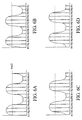
- FIG. 6A, 6B, 6C and 6D are wave forms illustrating the operation of the invention.
- FIG. 7 is a cross-sectional view of a voice coil actuator incorporating the position sensor of the present invention.
- FIG. 8 is a end view taken along the
line 8/8 of FIG. 7. - FIG. 9A is another illustration of FIG. 3B.
- FIG. 9B is the characteristic curve of the electrical output provided by FIG. 9A.
- FIG. 9C is an alternate embodiment of FIG. 9A.
- FIG. 9D is a characteristic output of the alternate embodiment shown in FIG. 9C.
- FIG. 9E is an alternate embodiment of FIG. 9A.
- FIG. 9F is a characteristic output of the alternate embodiment shown in FIG. 9E.
- Referring now to FIGS. 1 and 2 these illustrate the angular position sensor of the parent application where the
disk 10 illustrates both the transmit and receive sections or disks which contains six identical loop antenna coils designated for the transmit portion T1-T6 and for the receive section R1-R6. Acoupler disk 11 as illustrated in FIG. 2 is sandwiched between the transmit and receive disks and rotation of the crescent-shaped conductive portion of the coupler disk causes a phase shift in the signals from the receive coils which is proportional to rotary or angular displacement. As illustrated in FIG. 1, the coils are spaced 60° apart. - The present invention utilizes the above principle to measure linear displacement. Thus, FIG. 3 A is a
transmitter section 13 having six inductive coils T1-T6 arranged in a rectilinear pattern with a total distance La with a width of Lb. A similar rectilinear receivesection 14, FIG. 3C, has similar receive coils R1-R6 and includes a specialized electronics integratedcircuit unit 15 to provide output voltages designated Rout for each receive coil. Then juxtaposed between the transmitter andreceiver sections coupler section 12 having substantially symmetrical diamond shapedcoupler patterns 51 and 52 (see FIG. 3B) which are conductive with a nominal length of each pattern being designated Lc. Thus, movement of the coupler section in thedirection 53 attenuates the inductive coupling between transmitter andreceiver sections - FIG. 9A shows the
coupler section 12 and the electrical signal output related to the distance Lc is illustrated as a straight line in FIG. 9B. To generate an effective signal, generally the total length of theslider section 12 is as illustrated equal to Lc plus La. Thus thepatterns section slider section 12, a cycle counter is required to identify the effective revolutions or repetitions. This insures that the transmitter and receiver are exposed to the total length of the pattern on theslider section 12 at all times. - FIG. 4 illustrates the transmitter and
receiver sections coupler section 12 interposed, which will move in a linear manner as indicated by the arow 53, in association with the electrical signal processing circuit. Asignal source 17 supplies a signal, Fc to the coils of the transmitsection 13 which are inductively coupled to receivesection 14 and attenuated by theslider section 12.Signal 17 is also connected to a digital mixer andwaveform generator 16 which also has as aninput 31, the six receive coils, onoutput line 32, a set (S) signal is supplied to an RS flipflop. - Since the coupler or slider section will interrupt and attenuate the signal amplitudes based on the coupler pattern with respect to the position of each receiver coil, six different amplitude signals are simultaneously generated by an amplifier A1 and then input through a lowpass filter and limiting amplifier A2. The output signal of amplifier A2 is illustrated in FIGS. 6A, 6B, 6C and 6D which represents four different linear positions of the coupler or slider. Their phase shift is proportional to the linear position of the coupler or slider.
- Referring back to FIG. 4 comparator A3 then converts these waveforms to a square wave at
output 36 which drives the R input of the RS flipflop. This produces a pulse width modulator (PWM) output where the width of the pulse is exactly proportional to the amount of movement of the slider. Filter A4 provides an alternative analog output. - FIG. 5 illustrates the digital mixer and
waveform generator 16 and how it is related to the transmitter and receivecoils line 10. - An actual practical example of the position sensor of the present invention for measuring the displacement of a voice coil actuator is illustrated in FIGS. 7 and 8, where FIG. 7 is a
voice coil actuator 61 incorporating the position sensor and FIG. 8 shows the position sensor with its transmitsection 13, slider orcoupler section 12 andreceiver section 14 incorporated in the actuator. The transmitter and receiver are, of course, affixed to theframe 62 of the voice coil actuator with coupler orslider 12 as best illustrated in FIG. 7 being connected only tocoil holder 63, which moves in the direction as indicated by thearrow 64. It would be coupled to an actuated device such as the valve lifter of a diesel engine or some control device to control vehicle height.Movable coil holder 63 ofactuator 61 includes atubular coil 66 wrapped around it which interacts with the cylindrical ferromagneticpermanent magnet 67 through theair gap 68 in a manner well known in the art. The fixedouter frame 62 of the voice coil actuator is composed of soft iron for a flux return and is, of course, cylindrical in shape. The voice coil actuator may be used in conjunction with built in feedback control. - Referring now to FIGS. 9 in their various forms, as was discussed the diamond shape of the symmetrical pattern on the
slider section 12 illustrated in FIG. 9A results in the linear pattern of FIG. 9B. If a second order characteristic is desired at either one end or the other end of movement of theslider 12, as illustrated in either FIGS. 9D and 9F, then the patterns of FIGS. 9C, and 9E, respectively, may be provided where in FIG. 9C the rate of change toward the maximum of the pattern is greater and in 9E the rate of change at the beginning of the pattern is greater. - Thus a linear position sensor has been provided.
Claims (5)
- A position sensor for sensing rectilinear movement of an object along an axis comprising:a pair of spaced substantially rectilinear radio transmit (13) and receive (14) sections juxtaposed on said axis facing each other with a coupler section (12) between them, said coupler being moveable along said axis and connected to said object;said receive section (14) carrying a predetermined number n of inductive coils (R1-6) segmentally arranged in a rectilinear pattern at different positions along said receive section;said transmit section carrying coil means in a rectilinear pattern similar to said receive section and driven by a signal source (16) at a predetermined radio frequency for inductive coupling to said coils of said receive section (14);said coupler section (12) carrying at least one symmetrical conducive pattern (51, 52) for attenuating said inductive coupling, said pattern having linear positions of maximum and minimum attenuation with respect to any one of said plurality n of inductive coils carried by said receive section (14), intermediate positions of said pattern between said maximum and minimum providing substantially proportionate attenuations;a digital mixer and waveform generator (16) connected to said n inductive coils (R1-6) and arranged to mix the received signal from each of the n inductive coils with a respective one of a plurality of local oscillator signals (L01-06), each of the local oscillator signals having an evenly spaced phase which is a different integer multiple of 360° divided by the number n said n, where said integer is less than or equal to nmeans for summing said n mixed signals said summation producing a substantially sinusoidal waveform whose phase shift varies in proportion to the linear movement of said coupler section; andmeans for sensing said phase shift.
- A position sensor as in claim 1 where said conductive coupler pattern is non-linear between said maximum and minimum.
- A position sensor as in claim 1 or claim 2 where the total coupler pattern is longer than the transmit pattern.
- A position sensor as in claim 3 where a single symmetrical coupler pattern is equal to or shorter than said transmit pattern.
- A position sensor as in claim 3 or claim 4 where the effective linear measurement distance of said coupler section is one less than the plurality of symmetrical coupler patterns.
Applications Claiming Priority (2)
| Application Number | Priority Date | Filing Date | Title |
|---|---|---|---|
| US764840 | 2001-01-17 | ||
| US09/764,840 US6448759B2 (en) | 1999-09-07 | 2001-01-17 | Non-contact linear position sensor for motion control applications with inductive attenuating coupler |
Publications (3)
| Publication Number | Publication Date |
|---|---|
| EP1225426A2 EP1225426A2 (en) | 2002-07-24 |
| EP1225426A3 EP1225426A3 (en) | 2003-09-03 |
| EP1225426B1 true EP1225426B1 (en) | 2005-09-21 |
Family
ID=25071944
Family Applications (1)
| Application Number | Title | Priority Date | Filing Date |
|---|---|---|---|
| EP02250199A Expired - Lifetime EP1225426B1 (en) | 2001-01-17 | 2002-01-11 | A non-contact linear position sensor |
Country Status (4)
| Country | Link |
|---|---|
| US (1) | US6448759B2 (en) |
| EP (1) | EP1225426B1 (en) |
| JP (1) | JP2002340611A (en) |
| DE (1) | DE60206201T2 (en) |
Cited By (1)
| Publication number | Priority date | Publication date | Assignee | Title |
|---|---|---|---|---|
| EP2072960A2 (en) | 2007-12-21 | 2009-06-24 | Pepperl + Fuchs GmbH | Incremental displacement sensor and method for determining the displacement of an object relative to another object |
Families Citing this family (24)
| Publication number | Priority date | Publication date | Assignee | Title |
|---|---|---|---|---|
| US6985018B2 (en) * | 2004-03-29 | 2006-01-10 | Bei Sensors & Systems Company, Inc. | Programmable, multi-turn, pulse width modulation circuit for a non-contact angular position sensor |
| US7538544B2 (en) * | 2004-04-09 | 2009-05-26 | Ksr Technologies Co. | Inductive position sensor |
| CN100445694C (en) * | 2004-04-09 | 2008-12-24 | Ksr科技公司 | Inductive position sensor |
| US7276897B2 (en) | 2004-04-09 | 2007-10-02 | Ksr International Co. | Inductive position sensor |
| US7221154B2 (en) * | 2005-04-07 | 2007-05-22 | Ksr International Co. | Inductive position sensor with common mode corrective winding and simplified signal conditioning |
| US7292026B2 (en) * | 2005-04-08 | 2007-11-06 | Ksr International Co. | Signal conditioning system for inductive position sensor |
| US7449878B2 (en) | 2005-06-27 | 2008-11-11 | Ksr Technologies Co. | Linear and rotational inductive position sensor |
| US20070132449A1 (en) * | 2005-12-08 | 2007-06-14 | Madni Asad M | Multi-turn non-contact angular position sensor |
| DE102007015524A1 (en) | 2007-03-30 | 2008-10-09 | Cherry Gmbh | Method for producing an inductive damping element and inductive eddy current actuating element |
| US7906960B2 (en) * | 2007-09-21 | 2011-03-15 | Ksr Technologies Co. | Inductive position sensor |
| KR101219560B1 (en) * | 2007-11-20 | 2013-01-08 | 스미다 코포레이션 가부시키가이샤 | Rotation angle detecting sensor |
| US7911354B2 (en) | 2007-12-12 | 2011-03-22 | Ksr Technologies Co. | Inductive position sensor |
| US8729887B2 (en) * | 2009-11-09 | 2014-05-20 | Aisan Kogyo Kabushiki Kaisha | Rotation angle sensor |
| IT1401514B1 (en) * | 2010-08-03 | 2013-07-26 | Cifa S P A Unico Socio | PUMPING GROUP FOR A CONCRETE DISTRIBUTION MACHINE. |
| DE102012010014B3 (en) * | 2012-05-22 | 2013-09-26 | Sew-Eurodrive Gmbh & Co. Kg | Method for determining the position of a mobile unit and installation for carrying out a method |
| KR101415032B1 (en) | 2012-08-01 | 2014-08-06 | 주식회사 실리콘웍스 | Apparatus for detecting displacement and method thereof |
| US9464881B2 (en) * | 2012-08-01 | 2016-10-11 | Silicon Works Co., Ltd. | Displacement sensor, apparatus for detecting displacement, and method thereof |
| WO2016138546A2 (en) | 2015-02-27 | 2016-09-01 | Azoteq (Pty) Ltd | Inductance sensing |
| CN111094901A (en) | 2017-07-13 | 2020-05-01 | 阿佐特克(私人)有限公司 | Inductive sensing user interface device |
| EP3514500B1 (en) * | 2018-01-22 | 2021-01-06 | Melexis Technologies SA | Flux coupling srensor and target |
| EP3514559B1 (en) * | 2018-01-22 | 2021-08-25 | Melexis Technologies SA | Sensor package |
| EP3809098B1 (en) * | 2019-10-16 | 2022-04-06 | Ams Ag | Sensor front-end and method for operating a sensor device |
| EP3896399B1 (en) * | 2020-04-15 | 2022-11-09 | TE Connectivity Belgium BVBA | Sensor device and sensor assembly for measuring the rotational position of an element |
| DE102020114014B4 (en) * | 2020-05-26 | 2023-08-24 | Schaeffler Technologies AG & Co. KG | Position sensor, concentric slave cylinder and clutch device |
Family Cites Families (7)
| Publication number | Priority date | Publication date | Assignee | Title |
|---|---|---|---|---|
| US4697144A (en) * | 1984-04-19 | 1987-09-29 | Verify Electronics Limited | Position sensing apparatus |
| IE55855B1 (en) * | 1984-10-19 | 1991-01-30 | Kollmorgen Ireland Ltd | Position and speed sensors |
| US4893078A (en) * | 1987-05-28 | 1990-01-09 | Auchterlonie Richard C | Absolute position sensing using sets of windings of different pitches providing respective indications of phase proportional to displacement |
| DE4126921C2 (en) * | 1991-08-14 | 1996-01-18 | Elmeg | Device for inductive measurement of the position of a metal strip |
| EP0743508A2 (en) * | 1995-05-16 | 1996-11-20 | Mitutoyo Corporation | Induced current position transducer |
| FR2777649A1 (en) * | 1998-04-16 | 1999-10-22 | Jean Pierre Bazenet | Incremental measurement of displacement and position of objects, e.g. for machine shop controls |
| US6304076B1 (en) * | 1999-09-07 | 2001-10-16 | Bei Sensors & Systems Company, Inc. | Angular position sensor with inductive attenuating coupler |
-
2001
- 2001-01-17 US US09/764,840 patent/US6448759B2/en not_active Expired - Lifetime
-
2002
- 2002-01-11 DE DE60206201T patent/DE60206201T2/en not_active Expired - Fee Related
- 2002-01-11 EP EP02250199A patent/EP1225426B1/en not_active Expired - Lifetime
- 2002-01-17 JP JP2002045442A patent/JP2002340611A/en active Pending
Cited By (2)
| Publication number | Priority date | Publication date | Assignee | Title |
|---|---|---|---|---|
| EP2072960A2 (en) | 2007-12-21 | 2009-06-24 | Pepperl + Fuchs GmbH | Incremental displacement sensor and method for determining the displacement of an object relative to another object |
| DE102007061967A1 (en) * | 2007-12-21 | 2009-06-25 | Pepperl + Fuchs Gmbh | An incremental pathfinder and method for determining a displacement of a first object relative to a second object |
Also Published As
| Publication number | Publication date |
|---|---|
| JP2002340611A (en) | 2002-11-27 |
| US6448759B2 (en) | 2002-09-10 |
| US20010005133A1 (en) | 2001-06-28 |
| DE60206201D1 (en) | 2005-10-27 |
| EP1225426A2 (en) | 2002-07-24 |
| DE60206201T2 (en) | 2006-06-22 |
| EP1225426A3 (en) | 2003-09-03 |
Similar Documents
| Publication | Publication Date | Title |
|---|---|---|
| EP1225426B1 (en) | A non-contact linear position sensor | |
| US6810754B2 (en) | Magnetic-based transducer for measuring displacement | |
| CA2476543C (en) | Pulsed torque, force or general measurement with a coil and a magnetic field sensor (tangentially, circumferentially) | |
| US6661220B1 (en) | Antenna transponder configuration for angle measurement and data transmission | |
| US8106652B2 (en) | Apparatus for magnetizing a magnetizable element | |
| EP1774271B1 (en) | Sensor | |
| US6259249B1 (en) | Induction-type position measuring apparatus | |
| US5412317A (en) | Position detector utilizing absolute and incremental position sensors in combination | |
| CA1139394A (en) | 360 degree linear variable phase transformer | |
| CN110657826B (en) | Scale structure for inductive position encoder | |
| US6236200B1 (en) | Magnetic metal sensor and method for detecting magnetic metal | |
| US5404101A (en) | Rotary sensing device utilizing a rotating magnetic field within a hollow toroid core | |
| EP1971990A1 (en) | Sensor | |
| US9574865B2 (en) | Method and apparatus for sensing magnetic fields | |
| EP1456617A1 (en) | Magnetic torque/force transducer | |
| JP2004170273A (en) | Displacement sensor | |
| CN113677967B (en) | Torque sensor with inductively coupled and intermeshed components | |
| JPH0774741B2 (en) | Moving amount detector | |
| WO2017216421A2 (en) | Position sensor | |
| JPH01287433A (en) | Torque detecting device for rotary shaft | |
| JPH04198805A (en) | Device for detecting rotational displacement angle | |
| JPH0760098B2 (en) | Position sensor |
Legal Events
| Date | Code | Title | Description |
|---|---|---|---|
| PUAI | Public reference made under article 153(3) epc to a published international application that has entered the european phase |
Free format text: ORIGINAL CODE: 0009012 |
|
| AK | Designated contracting states |
Kind code of ref document: A2 Designated state(s): AT BE CH CY DE DK ES FI FR GB GR IE IT LI LU MC NL PT SE TR |
|
| AX | Request for extension of the european patent |
Free format text: AL;LT;LV;MK;RO;SI |
|
| PUAL | Search report despatched |
Free format text: ORIGINAL CODE: 0009013 |
|
| AK | Designated contracting states |
Kind code of ref document: A3 Designated state(s): AT BE CH CY DE DK ES FI FR GB GR IE IT LI LU MC NL PT SE TR |
|
| AX | Request for extension of the european patent |
Extension state: AL LT LV MK RO SI |
|
| 17P | Request for examination filed |
Effective date: 20031024 |
|
| 17Q | First examination report despatched |
Effective date: 20040329 |
|
| AKX | Designation fees paid |
Designated state(s): DE FR GB |
|
| GRAP | Despatch of communication of intention to grant a patent |
Free format text: ORIGINAL CODE: EPIDOSNIGR1 |
|
| GRAS | Grant fee paid |
Free format text: ORIGINAL CODE: EPIDOSNIGR3 |
|
| GRAA | (expected) grant |
Free format text: ORIGINAL CODE: 0009210 |
|
| AK | Designated contracting states |
Kind code of ref document: B1 Designated state(s): DE FR GB |
|
| REG | Reference to a national code |
Ref country code: GB Ref legal event code: FG4D |
|
| REF | Corresponds to: |
Ref document number: 60206201 Country of ref document: DE Date of ref document: 20051027 Kind code of ref document: P |
|
| ET | Fr: translation filed | ||
| PLBE | No opposition filed within time limit |
Free format text: ORIGINAL CODE: 0009261 |
|
| STAA | Information on the status of an ep patent application or granted ep patent |
Free format text: STATUS: NO OPPOSITION FILED WITHIN TIME LIMIT |
|
| 26N | No opposition filed |
Effective date: 20060622 |
|
| PGFP | Annual fee paid to national office [announced via postgrant information from national office to epo] |
Ref country code: GB Payment date: 20070125 Year of fee payment: 6 |
|
| PGFP | Annual fee paid to national office [announced via postgrant information from national office to epo] |
Ref country code: DE Payment date: 20070228 Year of fee payment: 6 |
|
| PGFP | Annual fee paid to national office [announced via postgrant information from national office to epo] |
Ref country code: FR Payment date: 20070117 Year of fee payment: 6 |
|
| GBPC | Gb: european patent ceased through non-payment of renewal fee |
Effective date: 20080111 |
|
| PG25 | Lapsed in a contracting state [announced via postgrant information from national office to epo] |
Ref country code: DE Free format text: LAPSE BECAUSE OF NON-PAYMENT OF DUE FEES Effective date: 20080801 |
|
| REG | Reference to a national code |
Ref country code: FR Ref legal event code: ST Effective date: 20081029 |
|
| PG25 | Lapsed in a contracting state [announced via postgrant information from national office to epo] |
Ref country code: GB Free format text: LAPSE BECAUSE OF NON-PAYMENT OF DUE FEES Effective date: 20080111 |
|
| PG25 | Lapsed in a contracting state [announced via postgrant information from national office to epo] |
Ref country code: FR Free format text: LAPSE BECAUSE OF NON-PAYMENT OF DUE FEES Effective date: 20080131 |