EP1225369A2 - Indexing apparatus and method of assembling the same - Google Patents
Indexing apparatus and method of assembling the same Download PDFInfo
- Publication number
- EP1225369A2 EP1225369A2 EP02250082A EP02250082A EP1225369A2 EP 1225369 A2 EP1225369 A2 EP 1225369A2 EP 02250082 A EP02250082 A EP 02250082A EP 02250082 A EP02250082 A EP 02250082A EP 1225369 A2 EP1225369 A2 EP 1225369A2
- Authority
- EP
- European Patent Office
- Prior art keywords
- worm
- shaft
- worm shaft
- motor
- body frame
- Prior art date
- Legal status (The legal status is an assumption and is not a legal conclusion. Google has not performed a legal analysis and makes no representation as to the accuracy of the status listed.)
- Withdrawn
Links
Images


Classifications
-
- B—PERFORMING OPERATIONS; TRANSPORTING
- B23—MACHINE TOOLS; METAL-WORKING NOT OTHERWISE PROVIDED FOR
- B23Q—DETAILS, COMPONENTS, OR ACCESSORIES FOR MACHINE TOOLS, e.g. ARRANGEMENTS FOR COPYING OR CONTROLLING; MACHINE TOOLS IN GENERAL CHARACTERISED BY THE CONSTRUCTION OF PARTICULAR DETAILS OR COMPONENTS; COMBINATIONS OR ASSOCIATIONS OF METAL-WORKING MACHINES, NOT DIRECTED TO A PARTICULAR RESULT
- B23Q16/00—Equipment for precise positioning of tool or work into particular locations not otherwise provided for
- B23Q16/02—Indexing equipment
- B23Q16/022—Indexing equipment in which only the indexing movement is of importance
- B23Q16/025—Indexing equipment in which only the indexing movement is of importance by converting a continuous movement into a rotary indexing movement
-
- F—MECHANICAL ENGINEERING; LIGHTING; HEATING; WEAPONS; BLASTING
- F16—ENGINEERING ELEMENTS AND UNITS; GENERAL MEASURES FOR PRODUCING AND MAINTAINING EFFECTIVE FUNCTIONING OF MACHINES OR INSTALLATIONS; THERMAL INSULATION IN GENERAL
- F16H—GEARING
- F16H1/00—Toothed gearings for conveying rotary motion
- F16H1/02—Toothed gearings for conveying rotary motion without gears having orbital motion
- F16H1/04—Toothed gearings for conveying rotary motion without gears having orbital motion involving only two intermeshing members
- F16H1/12—Toothed gearings for conveying rotary motion without gears having orbital motion involving only two intermeshing members with non-parallel axes
- F16H1/16—Toothed gearings for conveying rotary motion without gears having orbital motion involving only two intermeshing members with non-parallel axes comprising worm and worm-wheel
-
- H—ELECTRICITY
- H02—GENERATION; CONVERSION OR DISTRIBUTION OF ELECTRIC POWER
- H02K—DYNAMO-ELECTRIC MACHINES
- H02K7/00—Arrangements for handling mechanical energy structurally associated with dynamo-electric machines, e.g. structural association with mechanical driving motors or auxiliary dynamo-electric machines
- H02K7/08—Structural association with bearings
- H02K7/081—Structural association with bearings specially adapted for worm gear drives
-
- H—ELECTRICITY
- H02—GENERATION; CONVERSION OR DISTRIBUTION OF ELECTRIC POWER
- H02K—DYNAMO-ELECTRIC MACHINES
- H02K7/00—Arrangements for handling mechanical energy structurally associated with dynamo-electric machines, e.g. structural association with mechanical driving motors or auxiliary dynamo-electric machines
- H02K7/10—Structural association with clutches, brakes, gears, pulleys or mechanical starters
- H02K7/116—Structural association with clutches, brakes, gears, pulleys or mechanical starters with gears
- H02K7/1163—Structural association with clutches, brakes, gears, pulleys or mechanical starters with gears where at least two gears have non-parallel axes without having orbital motion
- H02K7/1166—Structural association with clutches, brakes, gears, pulleys or mechanical starters with gears where at least two gears have non-parallel axes without having orbital motion comprising worm and worm-wheel
-
- F—MECHANICAL ENGINEERING; LIGHTING; HEATING; WEAPONS; BLASTING
- F16—ENGINEERING ELEMENTS AND UNITS; GENERAL MEASURES FOR PRODUCING AND MAINTAINING EFFECTIVE FUNCTIONING OF MACHINES OR INSTALLATIONS; THERMAL INSULATION IN GENERAL
- F16H—GEARING
- F16H57/00—General details of gearing
- F16H57/02—Gearboxes; Mounting gearing therein
- F16H57/021—Shaft support structures, e.g. partition walls, bearing eyes, casing walls or covers with bearings
- F16H2057/0213—Support of worm gear shafts
-
- F—MECHANICAL ENGINEERING; LIGHTING; HEATING; WEAPONS; BLASTING
- F16—ENGINEERING ELEMENTS AND UNITS; GENERAL MEASURES FOR PRODUCING AND MAINTAINING EFFECTIVE FUNCTIONING OF MACHINES OR INSTALLATIONS; THERMAL INSULATION IN GENERAL
- F16H—GEARING
- F16H55/00—Elements with teeth or friction surfaces for conveying motion; Worms, pulleys or sheaves for gearing mechanisms
- F16H55/02—Toothed members; Worms
- F16H55/22—Toothed members; Worms for transmissions with crossing shafts, especially worms, worm-gears
- F16H55/24—Special devices for taking up backlash
-
- Y—GENERAL TAGGING OF NEW TECHNOLOGICAL DEVELOPMENTS; GENERAL TAGGING OF CROSS-SECTIONAL TECHNOLOGIES SPANNING OVER SEVERAL SECTIONS OF THE IPC; TECHNICAL SUBJECTS COVERED BY FORMER USPC CROSS-REFERENCE ART COLLECTIONS [XRACs] AND DIGESTS
- Y10—TECHNICAL SUBJECTS COVERED BY FORMER USPC
- Y10T—TECHNICAL SUBJECTS COVERED BY FORMER US CLASSIFICATION
- Y10T29/00—Metal working
- Y10T29/51—Plural diverse manufacturing apparatus including means for metal shaping or assembling
- Y10T29/5124—Plural diverse manufacturing apparatus including means for metal shaping or assembling with means to feed work intermittently from one tool station to another
- Y10T29/5127—Blank turret
- Y10T29/5129—Rotary work - horizontal axis
-
- Y—GENERAL TAGGING OF NEW TECHNOLOGICAL DEVELOPMENTS; GENERAL TAGGING OF CROSS-SECTIONAL TECHNOLOGIES SPANNING OVER SEVERAL SECTIONS OF THE IPC; TECHNICAL SUBJECTS COVERED BY FORMER USPC CROSS-REFERENCE ART COLLECTIONS [XRACs] AND DIGESTS
- Y10—TECHNICAL SUBJECTS COVERED BY FORMER USPC
- Y10T—TECHNICAL SUBJECTS COVERED BY FORMER US CLASSIFICATION
- Y10T29/00—Metal working
- Y10T29/51—Plural diverse manufacturing apparatus including means for metal shaping or assembling
- Y10T29/5124—Plural diverse manufacturing apparatus including means for metal shaping or assembling with means to feed work intermittently from one tool station to another
- Y10T29/5127—Blank turret
- Y10T29/513—Stationary work
-
- Y—GENERAL TAGGING OF NEW TECHNOLOGICAL DEVELOPMENTS; GENERAL TAGGING OF CROSS-SECTIONAL TECHNOLOGIES SPANNING OVER SEVERAL SECTIONS OF THE IPC; TECHNICAL SUBJECTS COVERED BY FORMER USPC CROSS-REFERENCE ART COLLECTIONS [XRACs] AND DIGESTS
- Y10—TECHNICAL SUBJECTS COVERED BY FORMER USPC
- Y10T—TECHNICAL SUBJECTS COVERED BY FORMER US CLASSIFICATION
- Y10T29/00—Metal working
- Y10T29/51—Plural diverse manufacturing apparatus including means for metal shaping or assembling
- Y10T29/5152—Plural diverse manufacturing apparatus including means for metal shaping or assembling with turret mechanism
-
- Y—GENERAL TAGGING OF NEW TECHNOLOGICAL DEVELOPMENTS; GENERAL TAGGING OF CROSS-SECTIONAL TECHNOLOGIES SPANNING OVER SEVERAL SECTIONS OF THE IPC; TECHNICAL SUBJECTS COVERED BY FORMER USPC CROSS-REFERENCE ART COLLECTIONS [XRACs] AND DIGESTS
- Y10—TECHNICAL SUBJECTS COVERED BY FORMER USPC
- Y10T—TECHNICAL SUBJECTS COVERED BY FORMER US CLASSIFICATION
- Y10T74/00—Machine element or mechanism
- Y10T74/14—Rotary member or shaft indexing, e.g., tool or work turret
-
- Y—GENERAL TAGGING OF NEW TECHNOLOGICAL DEVELOPMENTS; GENERAL TAGGING OF CROSS-SECTIONAL TECHNOLOGIES SPANNING OVER SEVERAL SECTIONS OF THE IPC; TECHNICAL SUBJECTS COVERED BY FORMER USPC CROSS-REFERENCE ART COLLECTIONS [XRACs] AND DIGESTS
- Y10—TECHNICAL SUBJECTS COVERED BY FORMER USPC
- Y10T—TECHNICAL SUBJECTS COVERED BY FORMER US CLASSIFICATION
- Y10T74/00—Machine element or mechanism
- Y10T74/14—Rotary member or shaft indexing, e.g., tool or work turret
- Y10T74/1418—Preselected indexed position
- Y10T74/1424—Sequential
- Y10T74/1441—Geneva or mutilated gear drive
-
- Y—GENERAL TAGGING OF NEW TECHNOLOGICAL DEVELOPMENTS; GENERAL TAGGING OF CROSS-SECTIONAL TECHNOLOGIES SPANNING OVER SEVERAL SECTIONS OF THE IPC; TECHNICAL SUBJECTS COVERED BY FORMER USPC CROSS-REFERENCE ART COLLECTIONS [XRACs] AND DIGESTS
- Y10—TECHNICAL SUBJECTS COVERED BY FORMER USPC
- Y10T—TECHNICAL SUBJECTS COVERED BY FORMER US CLASSIFICATION
- Y10T74/00—Machine element or mechanism
- Y10T74/14—Rotary member or shaft indexing, e.g., tool or work turret
- Y10T74/1476—Rotary member or shaft indexing, e.g., tool or work turret with means to axially shift shaft
Definitions
- the present invention relates to an indexing apparatus useful for indexing an angle of rotation of a rotary table and the like having a worm gear mechanism; and a method of assembling the same.
- a worm gear mechanism 1 used for a related art apparatus for indexing an angle of rotation of a rotary table and the like, a rotary shaft 2 fixed to a rotary table (not shown) and a worm wheel 4 are joined together fixedly, and a worm 5 is meshed with this worm wheel 4, as shown in Fig. 1.
- the worm 5 is made integral with a worm shaft 6.
- the worm shaft 6 is supported rotatably at one end thereof on a taper roller bearing 8 provided on a body 1a of the worm gear mechanism 1, and at the other end thereof on a needle bearing 9.
- the worm shaft 6 is joined to a connecting shaft 7 via a coupling 3 so that these shafts are in one body, and further to a motor (not shown) via a connecting gear mechanism 11.
- a motor shaft 13 forming a rotary driving shaft for the motor (not shown) is connected to the gear mechanism 11, and this motor shaft 13 is connected to the worm shaft 6 via a gear train of the gear mechanism 11 and connecting shaft 7.
- the worm gear mechanism 1 has a low speed and a high torque, and is capable of driving a rotary table and the like smoothly. However, providing a certain degree of backlash between the meshed portions of the worm 5 and worm wheel 4 is usually necessary and indispensable, and among the gear train of the connecting gear mechanism 11, etc. connected to the motor shaft 13.
- a suitable level is selected by taking a point of compromise in accordance with the use of the apparatus and from the above-mentioned contradictory points of view.
- an indexing apparatus capable of being rotated at a high speed with a high accuracy have been unavailable.
- the present invention is directed to an indexing apparatus provided with a worm shaft having a worm thereon, a worm wheel meshed with the worm, and a motor for driving the worm shaft, the worm shaft and a shaft of the motor being connected together directly, e.g. by a direct connecting method and the like, without interposing a rotation transmission mechanism, such as gears, etc. therebetween.
- the invention has been made in view of the above-mentioned circumstances, and provides an indexing apparatus capable of holding down the quantity of backlash, being driven at a high speed with a high accuracy and assembled easily.
- Embodiments of the invention may also provide an indexing apparatus in accordance with the above indexing apparatus, in which a body frame supporting the worm wheel thereon rotatably is provided, the worm shaft being supported rotatably at both end portions thereof on bearings, the bearing for one end portion of the worm shaft being provided on the body frame, the bearing provided for a motor shaft-side portion which constitutes the other end portion of the worm shaft being fixed to a bearing fixing portion formed on a retainer member to which the motor is fixed.
- the invention further provides a method of assembling such an indexing apparatus, including providing a body frame on which a worm wheel is worm wheel-carrying body frame.
- Embodiments of the invention may also provide a method of assembling such an indexing apparatus in accordance with the above method, in which the method includes providing bearings around both end portions of the worm shaft, fixing one end portion of the worm shaft with the relative bearing to a bearing fixing portion formed on a retainer member to which a motor is fixed, and fixing the retainer member to the body frame, the worm shaft being thus fixed to the worm shaft fixing portion of the body frame.
- Fig. 1 is a schematic view in longitudinal section of a worm gear portion of a related art indexing apparatus.
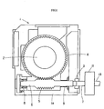
- Fig. 2 is a longitudinal sectional view of an embodiment of the indexing apparatus according to the invention.
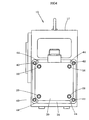
- Fig. 3 is a plan view of the same embodiment of the indexing apparatus according to the invention.
- Fig. 4 is a right side view of the same embodiment of the indexing apparatus according to the invention.
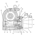
- Fig. 5 is a longitudinal sectional view showing another embodiment of the indexing apparatus according to the invention.
- FIG. 2 to Fig. 5 show an embodiment of the invention.
- An indexing apparatus 10 in this embodiment is provided with a worm gear mechanism, and used as an indexing apparatus for a rotary table and invention.
- An indexing apparatus 10 in this embodiment is provided with a worm gear mechanism, and used as an indexing apparatus for a rotary table and the like of a machine tool.
- This indexing apparatus 10 is provided with a rotary shaft 12 on which a rotary table (not shown) for placing thereon a work to be subjected to a predetermined process is fixed, and the rotary shaft 12 is supported rotatably on a body frame 17.
- a worm wheel 14 is fixed on this rotary shaft 12.
- a worm 15 is meshed with this worm wheel 14.
- the worm 15 is made integral with the worm shaft 16, and one end of the worm shaft 16 is supported rotatably in a fixing recess 25, which forms a worm shaft fixing portion of the body frame 17, via a bearing 18.
- the other end of the worm shaft 16 is also supported rotatably on a pair of bearings 19.
- the two bearings 19 are held on a retainer member 24 of a motor 20 which will be described later, and fixed in an opened portion 28 forming the other worm shaft fixing portion of the body frame 17.
- the worm shaft 16 is connected directly to a shaft 22 of the driving motor 20 without interposing a gear mechanism and the like therebetween.
- the worm shaft 16 is provided at one end portion 16a thereof with a fixing hole 32, in which the motor shaft 22 is fitted.
- the worm shaft 16 and motor shaft 22 are joined together in one body in the rotational direction owing to a key 40 fitted in a key way 34 formed in the fixing hole 32 and a key way 36 formed in the motor shaft 22.
- the motor 20 is fixed to the retainer member 24 by bolts 26 and the like, and the retainer member 24 is fixed in an opened portion 28 of the body frame 17 with a cylindrical fitting portion 30 of the former fitted in the opened portion.
- the two bearings 19 are fitted in the interior of the cylindrical fitting portion 30.
- the retainer member 24 is fixed at four portions thereof to the body frame 17 by bolts 42, and regulated to a proper meshing position by setscrews 44. The tight fixing of the parts is thereby carried out.
- the bearing 18 is fixed around a front end portion of the worm shaft 16.
- the bearings 19 are then fixed around the other end portion of the worm shaft 16.
- the second-mentioned end portion of the worm shaft 16 is inserted with the bearings 19 from a front end side of the cylindrical fitting portion 30 of the retainer member 24 therethrough.
- the second-mentioned bearings 19 are then inserted from the opposite side of the cylindrical fitting portion 30 of the retainer member 24 around the bearing shaft 16, and set in a position in which a projection on an inner portion of the cylindrical fitting portion 30 is sandwiched between the two bearings 19 without leaving a clearance therebetween.
- the motor shaft 22 is then fitted in the fixing hole 32 for the worm shaft 16.
- the key 40 is fitted in the key way 36 of the motor shaft 22, and inserted into the key way 34 of the fixing hole 32 for the worm shaft 16.
- the motor 20 is fixed to the retainer member 24 by the bolts 26 with the motor shaft 22 and worm shaft 16 in a unitarily combined state.
- the worm shaft 16 and worm 15 are then inserted with the cylindrical fitting portion 30 of the retainer member 24 into the opened portion 28 of the body frame 17.
- the worm shaft 16 and worm wheel 14 are positioned by the setscrews 44 shown in Fig. 2 or spacers 45 shown in Fig. 5, in such a manner that the worm shaft and worm wheel are in a proper meshing position, these shafts being then fixed to the body frame 17 by the bolts 42.
- the worm shaft 16 and motor shaft 22 are connected together directly, so that the rotation of the motor 20 is transmitted directly to the worm 15. Since a gear train is not provided between the motor and worm, a rattle and play due to a backlash and the like of gear train do not occur, and the rotation of the motor 20 is transmitted accurately to the worm wheel 12 via the worm shaft 16. Moreover, this enables the number of parts to be reduced, and contributes to the miniaturization of the apparatus and the reduction of the manufacturing cost.
- the worm shaft 16 and motor shaft 22 are fixed in a connected state in the body frame 17, so that the assembling man-day can be reduced. Since the worm shaft 16 is joined to the motor shaft 22 in advance, the assembling accuracy becomes high. Especially, the worm shaft 16 is retained with the bearings 19 in the cylindrical fitting portion 30 of the retainer member 24, and this enables the apparatus to be assembled simply with a higher accuracy.
- the indexing apparatus and the method of assembling the same according to the invention are not limited to the above-described embodiments.
- the method of connecting the worm shaft and motor shaft together directly may be replaced with a method of connecting these shafts together via a coupling having an automatic aligning function, or via a connecting device which does not shake, besides a method of connecting these shafts together concentrically.
- the indexing apparatus According to the indexing apparatus according to the invention, it has become possible to eliminate a gear train provided heretofore between the motor and worm, reduce driving play which is ascribed to the presence of a backlash of the gear, and carry out a more accurate position indexing operation. Moreover, this apparatus enables the simplification of the construction, the miniaturization of the apparatus and the reduction of the number of parts to be attained.
- the worm shaft and motor shaft are connected together directly in advance, and the resultant shafts are fixed to the body frame, so that the reduction of the assembling time and the improvement of the assembling accuracy can be attained.
- the worm shaft is fixed to the retainer member of the motor, and then to the body frame. Therefore, the worm shaft can be fixed more accurately, simply and firmly.
Landscapes
- Engineering & Computer Science (AREA)
- Mechanical Engineering (AREA)
- Power Engineering (AREA)
- General Engineering & Computer Science (AREA)
- Gear Transmission (AREA)
- Machine Tool Positioning Apparatuses (AREA)
- Manufacture Of Motors, Generators (AREA)
Abstract
Description
Claims (4)
- An indexing apparatus (10) provided with a worm shaft (16) having a worm (15) thereon, a worm wheel (14) meshed with the worm (15), and a motor (20) for driving the worm shaft (16), characterized in that:the worm shaft (16) and a shaft (22) of the motor (20) are connected together directly without interposing a rotation transmission mechanism therebetween.
- The indexing apparatus according to Claim 1, wherein:a body frame (17) supporting the worm wheel (14) thereon rotatably is provided, the worm shaft (16) being supported rotatably at both end portions thereof on bearings (18,19), the bearing (18) for one end portion of the worm shaft being provided on the body frame (17), the bearing (19) provided for a motor shaft-side portion which constitutes the other end portion of the worm shaft (16) being fixed to a bearing fixing portion formed on a retainer member (24) to which the motor (20) is fixed.
- A method of assembling the indexing apparatus, characterized by:providing a worm shaft (16) having a worm (15) thereon, a worm wheel (14) meshed with the worm (15), a body frame supporting the worm wheel (14) rotatably thereon and a motor (20) for driving the worm shaft (16), connecting the worm shaft (16) and a shaft (22) of the motor (20) together directly without interposing a rotation transmission mechanism therebetween, andfixing the worm shaft (16) to a worm shaft fixing portion of the body frame (17) with the worm shaft (16) and motor shaft (22) in a unitarily connected state.
- The method according to Claim 3, wherein the method includes:providing bearings (18,19) around both end portions of the worm shaft (16), fixing one end portion of the worm shaft with the relative bearing to a bearing fixing portion formed on a retainer member (24) to which the motor is fixed, andfixing the retainer member to the body frame (17), whereby the worm shaft (16) is fixed to the worm shaft fixing portion of the body frame (17).
Applications Claiming Priority (2)
| Application Number | Priority Date | Filing Date | Title |
|---|---|---|---|
| JP2001003771A JP2002205244A (en) | 2001-01-11 | 2001-01-11 | Indexing device and its assembling method |
| JP2001003771 | 2001-01-11 |
Publications (2)
| Publication Number | Publication Date |
|---|---|
| EP1225369A2 true EP1225369A2 (en) | 2002-07-24 |
| EP1225369A3 EP1225369A3 (en) | 2008-12-31 |
Family
ID=18872061
Family Applications (1)
| Application Number | Title | Priority Date | Filing Date |
|---|---|---|---|
| EP02250082A Withdrawn EP1225369A3 (en) | 2001-01-11 | 2002-01-07 | Indexing apparatus and method of assembling the same |
Country Status (4)
| Country | Link |
|---|---|
| US (1) | US6666109B2 (en) |
| EP (1) | EP1225369A3 (en) |
| JP (1) | JP2002205244A (en) |
| TW (1) | TW528641B (en) |
Cited By (1)
| Publication number | Priority date | Publication date | Assignee | Title |
|---|---|---|---|---|
| WO2013179000A1 (en) * | 2012-05-28 | 2013-12-05 | Renishaw Plc | A worm drive, a kit, a device and a fixing method |
Families Citing this family (9)
| Publication number | Priority date | Publication date | Assignee | Title |
|---|---|---|---|---|
| JP5128314B2 (en) | 2008-03-03 | 2013-01-23 | 有限会社メーコー精機 | Ball reducer and rotary table device using the same |
| KR101341661B1 (en) * | 2012-12-18 | 2013-12-16 | 김성곤 | Rotary table apparatus including multi worm shaft |
| US10619718B2 (en) * | 2014-10-09 | 2020-04-14 | Nsk Ltd. | Worm reducer and method of assembling worm reducer |
| CN104308655A (en) * | 2014-10-17 | 2015-01-28 | 芜湖洪金机床有限公司 | Worm dividing head for machine tool |
| US20170326702A1 (en) * | 2016-05-12 | 2017-11-16 | Tsudakoma Kogyo Kabushiki Kaisha | Rotary table device for machine tool |
| KR102020790B1 (en) * | 2018-01-31 | 2019-11-04 | 위월드 주식회사 | Worm Gear Assembly having backlash control structure And pop-up antenna |
| KR102033558B1 (en) * | 2018-05-18 | 2019-10-17 | 주식회사 만도 | Reducer of Electric power steering apparatus |
| CN109630618A (en) * | 2019-01-17 | 2019-04-16 | 杭州星河传动机械研究院有限公司 | A synchronous high-load reducer |
| JP7329562B2 (en) * | 2021-06-23 | 2023-08-18 | 日本トムソン株式会社 | table drive |
Family Cites Families (17)
| Publication number | Priority date | Publication date | Assignee | Title |
|---|---|---|---|---|
| GB570600A (en) * | 1942-09-04 | 1945-07-13 | Michigan Tool Co | Improvements in or relating to worm gear mountings |
| US3704684A (en) * | 1971-08-18 | 1972-12-05 | Burton D Brown | Attachment for measuring coordinates in a milling machine |
| WO1983003378A1 (en) * | 1982-03-29 | 1983-10-13 | Earl Dean Bailey | Portable machining turntable |
| JPS61236459A (en) * | 1985-12-20 | 1986-10-21 | Sankyo Seisakusho:Kk | Intermittent dividing device |
| US4785513A (en) * | 1986-12-16 | 1988-11-22 | Hardinge Brothers | Turret having rotating and non-rotating tooling |
| JPH0649956Y2 (en) * | 1988-03-04 | 1994-12-14 | マブチモーター株式会社 | Small motor with worm reducer |
| JPH03270851A (en) * | 1990-03-19 | 1991-12-03 | Tsudakoma Corp | Driving device for rotary indexing table |
| JP3061210B2 (en) * | 1991-05-24 | 2000-07-10 | 豊和工業株式会社 | Compensation mechanism of indexing device |
| JPH05212467A (en) * | 1992-02-03 | 1993-08-24 | Amada Co Ltd | Automatic index device |
| JP3166877B2 (en) * | 1992-05-29 | 2001-05-14 | 津田駒工業株式会社 | Worm gear indexing mechanism |
| JP3270851B2 (en) | 1993-04-30 | 2002-04-02 | 日本キレート株式会社 | Garbage disposal container |
| US5497060A (en) * | 1993-06-21 | 1996-03-05 | Juergens, Iii; Albert M. | Positioning stage |
| US5433294A (en) * | 1994-05-18 | 1995-07-18 | Delaware Capital Formation, Inc. | Geared elevator system |
| US5540120A (en) * | 1994-11-22 | 1996-07-30 | Midwest Brake Bond Company | Index table with a two speed drive system |
| JPH10285870A (en) * | 1997-04-02 | 1998-10-23 | Mabuchi Motor Co Ltd | Small motor with reduction gear |
| JP3716616B2 (en) * | 1998-04-24 | 2005-11-16 | 日本精工株式会社 | Worm reducer and linear actuator with worm reducer |
| JP2002126958A (en) * | 2000-10-25 | 2002-05-08 | Sankyo Mfg Co Ltd | Rotary table device |
-
2001
- 2001-01-11 JP JP2001003771A patent/JP2002205244A/en active Pending
- 2001-12-19 US US10/025,308 patent/US6666109B2/en not_active Expired - Fee Related
- 2001-12-26 TW TW090132312A patent/TW528641B/en not_active IP Right Cessation
-
2002
- 2002-01-07 EP EP02250082A patent/EP1225369A3/en not_active Withdrawn
Cited By (1)
| Publication number | Priority date | Publication date | Assignee | Title |
|---|---|---|---|---|
| WO2013179000A1 (en) * | 2012-05-28 | 2013-12-05 | Renishaw Plc | A worm drive, a kit, a device and a fixing method |
Also Published As
| Publication number | Publication date |
|---|---|
| JP2002205244A (en) | 2002-07-23 |
| EP1225369A3 (en) | 2008-12-31 |
| US6666109B2 (en) | 2003-12-23 |
| TW528641B (en) | 2003-04-21 |
| US20020088305A1 (en) | 2002-07-11 |
Similar Documents
| Publication | Publication Date | Title |
|---|---|---|
| US10584787B2 (en) | Worm reduction gear | |
| US6666109B2 (en) | Indexing apparatus and method of assembling the same | |
| EP0841128B1 (en) | Wrist mechanism for an industrial robot | |
| JPH1182697A (en) | Planetary gear unit with backlash adjustment mechanism | |
| KR101456304B1 (en) | Driving device of rotary table | |
| EP1267095A2 (en) | Planetary gear device for reducing speed of an output shaft of a motor | |
| JP2000039057A (en) | Reduction gear | |
| WO2022196569A1 (en) | Assembly of gear and rotating shaft, and assembly method therefor | |
| WO2006118022A1 (en) | Motor shaft for micromotor, and micromotor | |
| KR101401204B1 (en) | Gear backlash controlling apparatus for manufacturing machine | |
| JP4517285B2 (en) | Electric power steering device | |
| JP2001514581A (en) | Rotary power tool with extension output shaft | |
| EP1166931A1 (en) | Turning machining tool | |
| JP2004122322A (en) | Rotation transmission mechanism, machine tool provided with the same, and tool holder | |
| JP2009275853A (en) | Output part structure of reduction gear | |
| JP2008267466A (en) | Case component manufacturing method | |
| JPH0852608A (en) | Workpiece rotary tool | |
| JPS61244940A (en) | Internal gear equipment in planetary gear mechanism | |
| JP4122125B2 (en) | Pinion mounting structure and series of gear shaft devices adopting this | |
| JP2004084927A (en) | Internal revolution type differential gear speed reducer | |
| JP2006144888A (en) | Eccentric oscillating gear unit | |
| CN219734172U (en) | One-way rotation is with no key connection speed reducer | |
| JP2004132529A (en) | Gearing device | |
| KR101019956B1 (en) | Rotary tool holder with separate spindle | |
| JP3409529B2 (en) | Processing method and fixing method of shaft member mounting hole for thin plate and micro drive unit |
Legal Events
| Date | Code | Title | Description |
|---|---|---|---|
| PUAI | Public reference made under article 153(3) epc to a published international application that has entered the european phase |
Free format text: ORIGINAL CODE: 0009012 |
|
| AK | Designated contracting states |
Kind code of ref document: A2 Designated state(s): AT BE CH CY DE DK ES FI FR GB GR IE IT LI LU MC NL PT SE TR |
|
| AX | Request for extension of the european patent |
Free format text: AL;LT;LV;MK;RO;SI |
|
| PUAL | Search report despatched |
Free format text: ORIGINAL CODE: 0009013 |
|
| AK | Designated contracting states |
Kind code of ref document: A3 Designated state(s): AT BE CH CY DE DK ES FI FR GB GR IE IT LI LU MC NL PT SE TR |
|
| AX | Request for extension of the european patent |
Extension state: AL LT LV MK RO SI |
|
| 17P | Request for examination filed |
Effective date: 20090601 |
|
| AKX | Designation fees paid |
Designated state(s): CH DE FR IT LI |
|
| 17Q | First examination report despatched |
Effective date: 20091008 |
|
| STAA | Information on the status of an ep patent application or granted ep patent |
Free format text: STATUS: THE APPLICATION IS DEEMED TO BE WITHDRAWN |
|
| 18D | Application deemed to be withdrawn |
Effective date: 20100219 |