EP1225264A1 - Apparatus for the production of non-woven fabric thermally bonded by calendering - Google Patents
Apparatus for the production of non-woven fabric thermally bonded by calendering Download PDFInfo
- Publication number
- EP1225264A1 EP1225264A1 EP02000922A EP02000922A EP1225264A1 EP 1225264 A1 EP1225264 A1 EP 1225264A1 EP 02000922 A EP02000922 A EP 02000922A EP 02000922 A EP02000922 A EP 02000922A EP 1225264 A1 EP1225264 A1 EP 1225264A1
- Authority
- EP
- European Patent Office
- Prior art keywords
- roll
- web
- calender
- rolls
- conveyor belt
- Prior art date
- Legal status (The legal status is an assumption and is not a legal conclusion. Google has not performed a legal analysis and makes no representation as to the accuracy of the status listed.)
- Withdrawn
Links
- 238000004519 manufacturing process Methods 0.000 title claims abstract description 7
- 239000004745 nonwoven fabric Substances 0.000 title claims abstract description 6
- 238000003490 calendering Methods 0.000 title description 2
- 238000009960 carding Methods 0.000 claims abstract description 9
- 238000001125 extrusion Methods 0.000 claims abstract description 4
- 238000000034 method Methods 0.000 claims abstract description 4
- 239000012530 fluid Substances 0.000 claims description 3
- 230000006835 compression Effects 0.000 claims description 2
- 238000007906 compression Methods 0.000 claims description 2
- 238000011144 upstream manufacturing Methods 0.000 claims description 2
- 238000001816 cooling Methods 0.000 claims 2
- 239000002826 coolant Substances 0.000 claims 1
- 230000000694 effects Effects 0.000 description 4
- 230000001174 ascending effect Effects 0.000 description 3
- 230000008901 benefit Effects 0.000 description 3
- 230000015572 biosynthetic process Effects 0.000 description 2
- 230000005484 gravity Effects 0.000 description 2
- 230000001788 irregular Effects 0.000 description 2
- 230000035699 permeability Effects 0.000 description 2
- 239000004952 Polyamide Substances 0.000 description 1
- 239000004743 Polypropylene Substances 0.000 description 1
- 230000008859 change Effects 0.000 description 1
- 238000007599 discharging Methods 0.000 description 1
- 239000002184 metal Substances 0.000 description 1
- 230000004048 modification Effects 0.000 description 1
- 238000012986 modification Methods 0.000 description 1
- 230000002093 peripheral effect Effects 0.000 description 1
- 229920002647 polyamide Polymers 0.000 description 1
- 229920006149 polyester-amide block copolymer Polymers 0.000 description 1
- -1 polypropylene Polymers 0.000 description 1
- 229920001155 polypropylene Polymers 0.000 description 1
- 229920001169 thermoplastic Polymers 0.000 description 1
- 239000004416 thermosoftening plastic Substances 0.000 description 1
- 230000032258 transport Effects 0.000 description 1
Images


Classifications
-
- D—TEXTILES; PAPER
- D04—BRAIDING; LACE-MAKING; KNITTING; TRIMMINGS; NON-WOVEN FABRICS
- D04H—MAKING TEXTILE FABRICS, e.g. FROM FIBRES OR FILAMENTARY MATERIAL; FABRICS MADE BY SUCH PROCESSES OR APPARATUS, e.g. FELTS, NON-WOVEN FABRICS; COTTON-WOOL; WADDING ; NON-WOVEN FABRICS FROM STAPLE FIBRES, FILAMENTS OR YARNS, BONDED WITH AT LEAST ONE WEB-LIKE MATERIAL DURING THEIR CONSOLIDATION
- D04H1/00—Non-woven fabrics formed wholly or mainly of staple fibres or like relatively short fibres
- D04H1/40—Non-woven fabrics formed wholly or mainly of staple fibres or like relatively short fibres from fleeces or layers composed of fibres without existing or potential cohesive properties
- D04H1/54—Non-woven fabrics formed wholly or mainly of staple fibres or like relatively short fibres from fleeces or layers composed of fibres without existing or potential cohesive properties by welding together the fibres, e.g. by partially melting or dissolving
- D04H1/542—Adhesive fibres
- D04H1/544—Olefin series
-
- D—TEXTILES; PAPER
- D04—BRAIDING; LACE-MAKING; KNITTING; TRIMMINGS; NON-WOVEN FABRICS
- D04H—MAKING TEXTILE FABRICS, e.g. FROM FIBRES OR FILAMENTARY MATERIAL; FABRICS MADE BY SUCH PROCESSES OR APPARATUS, e.g. FELTS, NON-WOVEN FABRICS; COTTON-WOOL; WADDING ; NON-WOVEN FABRICS FROM STAPLE FIBRES, FILAMENTS OR YARNS, BONDED WITH AT LEAST ONE WEB-LIKE MATERIAL DURING THEIR CONSOLIDATION
- D04H1/00—Non-woven fabrics formed wholly or mainly of staple fibres or like relatively short fibres
- D04H1/40—Non-woven fabrics formed wholly or mainly of staple fibres or like relatively short fibres from fleeces or layers composed of fibres without existing or potential cohesive properties
- D04H1/54—Non-woven fabrics formed wholly or mainly of staple fibres or like relatively short fibres from fleeces or layers composed of fibres without existing or potential cohesive properties by welding together the fibres, e.g. by partially melting or dissolving
-
- D—TEXTILES; PAPER
- D04—BRAIDING; LACE-MAKING; KNITTING; TRIMMINGS; NON-WOVEN FABRICS
- D04H—MAKING TEXTILE FABRICS, e.g. FROM FIBRES OR FILAMENTARY MATERIAL; FABRICS MADE BY SUCH PROCESSES OR APPARATUS, e.g. FELTS, NON-WOVEN FABRICS; COTTON-WOOL; WADDING ; NON-WOVEN FABRICS FROM STAPLE FIBRES, FILAMENTS OR YARNS, BONDED WITH AT LEAST ONE WEB-LIKE MATERIAL DURING THEIR CONSOLIDATION
- D04H1/00—Non-woven fabrics formed wholly or mainly of staple fibres or like relatively short fibres
- D04H1/40—Non-woven fabrics formed wholly or mainly of staple fibres or like relatively short fibres from fleeces or layers composed of fibres without existing or potential cohesive properties
- D04H1/54—Non-woven fabrics formed wholly or mainly of staple fibres or like relatively short fibres from fleeces or layers composed of fibres without existing or potential cohesive properties by welding together the fibres, e.g. by partially melting or dissolving
- D04H1/542—Adhesive fibres
- D04H1/549—Polyamides
-
- D—TEXTILES; PAPER
- D04—BRAIDING; LACE-MAKING; KNITTING; TRIMMINGS; NON-WOVEN FABRICS
- D04H—MAKING TEXTILE FABRICS, e.g. FROM FIBRES OR FILAMENTARY MATERIAL; FABRICS MADE BY SUCH PROCESSES OR APPARATUS, e.g. FELTS, NON-WOVEN FABRICS; COTTON-WOOL; WADDING ; NON-WOVEN FABRICS FROM STAPLE FIBRES, FILAMENTS OR YARNS, BONDED WITH AT LEAST ONE WEB-LIKE MATERIAL DURING THEIR CONSOLIDATION
- D04H1/00—Non-woven fabrics formed wholly or mainly of staple fibres or like relatively short fibres
- D04H1/40—Non-woven fabrics formed wholly or mainly of staple fibres or like relatively short fibres from fleeces or layers composed of fibres without existing or potential cohesive properties
- D04H1/54—Non-woven fabrics formed wholly or mainly of staple fibres or like relatively short fibres from fleeces or layers composed of fibres without existing or potential cohesive properties by welding together the fibres, e.g. by partially melting or dissolving
- D04H1/542—Adhesive fibres
- D04H1/55—Polyesters
Definitions
- the present invention relates to apparatus for the production of non-woven fabric in which a web of fibres produced by carding or extrusion by the "spun-bonding" method is supplied, by means of a conveyor belt, to a calender comprising a pair of heated, contrarotating rolls.
- Apparatus of the above-mentioned type is known from EP-A-0 867 550; in this apparatus, the axes of rotation of the two heated calender rolls, to which a web produced by carding is supplied, lie in a vertical plane and the point of contact between the two rolls is slightly below the region in which the web is output from the conveyor belt.
- a first disadvantage of this apparatus lies in the fact that the unsupported portion of the web disposed between the region in which it is detached from the conveyor belt and the region of contact between the calender rolls is substantially horizontal. This portion of the web is consequently subjected, by the effect of gravity, to a force perpendicular to its direction of movement, and this tends to damage the web which is not yet bonded.
- the web is stretched by an increase in the speed of rotation of the calender rolls relative to the speed of movement of the conveyor belt, which corresponds to the speed at which the web is produced by carding.
- the amount of stretch must be very limited to avoid reducing the transverse strength of the web to below the minimum value required by the users of the product, and to prevent the formation of holes in the web.
- a further disadvantage of this apparatus lies in the fact that the above-mentioned unsupported portion of the web is subject to the effect of an irregular ascending stream of hot air which is generated by the lower calender roll and causes deformation of the web. It is not possible to compensate fully for this deformation by increased stretching since the stretching must necessarily be limited for the reasons indicated above.
- the unsupported portion of the web is arranged substantially vertically, rather than horizontally, so that the web is subjected, by the effect of gravity, to a force which is directed along the axis of movement of the web, rather than perpendicular thereto.
- One of the causes of deformation of the web is thus eliminated, but the web is still subject to the effect of an irregular ascending stream of hot air which, in this case, is generated by both of the heated calender rolls so that, in this case also, increased stretching is required but must not exceed a certain limit, for the reasons indicated above.
- This apparatus also comprises a suction roll which is in contact both with the return roll of the conveyor belt in the vicinity of which the web leaves the belt, and with the lower calender roll.
- This suction roll is constituted by a perforated, hollow roll which rotates in the opposite direction to the return roll on a hollow, fixed roll the surface of which has an interruption of an angular extent corresponding to that of the surface of the perforated roll disposed between the above-mentioned contact points.
- the internal cavity of the hollow, fixed roll communicates with a suction source so that, in operation, the web adheres to the suction roll by suction on its path between the conveyor belt and the lower calender roll, which is generally knurled.
- the web also adheres to the lower calender roll on its path between the point of contact of this lower roll with the suction roll and the point of contact of the lower roll with the upper calender roll, which is generally smooth.
- the web thus undergoes preliminary bonding on these paths before it is bonded thermally.
- peripheral velocities of the suction roll and of the two calender rolls are almost equal to the speed at which the web is transported on the conveyor belt (which, as stated above, corresponds to the speed at which the web is produced by the carding) so that the web is not stretched during the bonding step.
- the subject of the present invention is apparatus for the production of non-woven fabric of the type indicated above, having the characteristic which forms the subject of Claim 1.
- thermoplastic fibres such as polypropylene, polyester or polyamide fibres, which is produced by carding in known manner, is supplied on a conveyor belt, indicated 1, that is impermeable to air.
- a return roll of the belt 1 is indicated 2; the web leaves the belt in the region of this return roll in order to be fed - in the manner which will be described below - between the two heated rolls 3, 4 of a calender which bonds the web thermally.
- the first roll 3, which is the first roll with which the web comes into contact, is knurled, whereas the second roll 4 is smooth.
- the fibres of the web are welded together at points, in known manner, as a result of their passage between the two rolls 3 and 4.
- the bonded web 5 emerging from the calender 1 is intended for use in the production of non-woven fabrics.
- the axes of the two calender rolls 3, 4 lie in a horizontal plane and the tops of the rolls are situated slightly below a horizontal plane tangential to the top of the return roll 2.
- the roll 6 compresses the web, reducing its thickness and thus bonding together the two or more webs of which it is composed.
- the holes provided in the surface of the roll 6 enable the air expelled from the web 1 as a result of its compression by the roll 6 to be discharged into the cavity inside the roll 6, which is in communication with the external atmosphere.
- the following roll 7 exerts a pressure on the web in order to cause it to adhere to the first calender roll 3 at a point situated in the vicinity of the top of the roll 3.
- a portion of the roll 7 extends below a horizontal plane tangential to the return roll 2 so that the roll 7 forces the web to form a loop on its path between the rolls 2 and 3.
- the roll 7 also helps to discharge the air still contained in the web into the interior of the roll.
- the surface of the roll 7 preferably has elongate holes 8 extending transversely relative to the direction F of the movement of the web on the conveyor belt 1 and arranged in rows which are parallel to the axis of rotation and are spaced apart uniformly, the holes of each row being offset relative to the holes of the two adjacent rows.
- the holes 8 may have a length of 15 mm and a width of 5 mm and the holes of each row may be spaced apart by 10 mm.
- the elongate holes, indicated 8a are inclined to the axis of rotation of the roll 7 alternately in opposite directions relative to the direction F of advance of the web.
- the axis of each hole 8a is preferably inclined at an angle of between 30 and 45° to the axis of rotation of the roll 7.
- the holes may have a circular or polygonal outline, or the surface of the roll 7 may be constituted by a metal mesh.
- a first cylindrical screen, indicated 9, faces the surface of the roll 3 remote from that which faces the roll 4.
- the screen 9 produces a laminar air-jet directed towards the region in which the distance between the roll 3 and the overlying following roll 7 is shortest.
- This air-jet which is discharged through the holes in the roll 7, directs and compresses the web in a uniform manner so that it is possible to operate with a very limited stretch, avoiding the disadvantages connected with a large amount of stretch.
- the screen 9 is supported by a fixed, hollow body 10 containing a fluid which is circulated, by means of a pump 11, in a circuit including an intake duct 12, a heat exchanger 13, and a delivery duct 14.
- This screen 9, and consequently the air directed thereby, are thus kept at a moderate temperature such as not to damage the web.
- a second screen 15 with a cylindrical profile faces the surface of the roll 3 disposed between the perforated following roll 7 and the region of contact between the calender rolls 3 and 4.
- the screen 15 produces a laminar air-jet which directs and compresses the web onto this surface of the roll 3 in a uniform manner. This prevents the ascending high-temperature air turbulence which would otherwise arise in the upper space between the two rolls 3 and 4 as a result of their rotation in opposite directions and the consequent damage to the web in the form of blisters, breakages, buckling and striation.
- the screen 15 is supported by a fixed, hollow body 16 containing a fluid which is circulated by means of a pump 17 in a circuit which comprises an intake duct 18, a heat exchanger 19, and a delivery duct 20.
- the advantages of the above-described web-bonding apparatus lie in the fact that it enables the air contained in the web to be discharged in a manner such as to bring about preliminary bonding of the fibres and to improve the adhesion of the web to the first calender roll.
- the speed of the conveyor belt and the speeds of the perforated rolls and of the calender rolls are not linked to one another so that it is possible to take full advantage of the good cohesion characteristics of the carded fibres, controlling the degree of stretch as required, which enables the production speed to be increased without changing the toughness value or the degree of isotropy of the product.
- This variant differs from the embodiment shown in Figure 1 in that the axes of the calender rolls 103 and 104 (which are arranged, as in Figure 1, below the horizontal plane in which the active pass of the conveyor belt 201 lies) lie in a vertical plane.
- the top of the first calender roll 103 is tangential to the above-mentioned horizontal plane and the lower surface of the perforated following roll 107 extends below this plane so that, as in the embodiment of Figure 1, a loop is formed, causing the web to adhere to the roll 103, conferring a limited tension on the web.
- the functions of the perforated pressure roll 106, of the perforated following roll 107, and of the screens 109 and 115 correspond to those of the corresponding parts described with reference to Figure 1.
- the perforated pressure roll indicated 6 in Figure 1 and 106 in Figure 4
- the axes of the rolls 203 and 204 lie in a vertical plane as in the embodiment shown in Figure 4, but are disposed above the horizontal plane in which the active pass of the conveyor lies, rather than below this plane.
- the perforated following roll 207 is disposed above the return roll 202 so that it also acts as a pressure roll for discharging the air from the web on its path between the point of contact A between the rolls 207 and 202 and the point of contact B between the rolls 207 and 203. A preliminary bonding of the web then takes place on its path between point B and the point of contact C between the calender rolls 203 and 204.
- the invention may also advantageously be applied to a web produced by extrusion, that is, when the well-known method known as "spun-bonding" is used.
Landscapes
- Engineering & Computer Science (AREA)
- Textile Engineering (AREA)
- Treatment Of Fiber Materials (AREA)
Abstract
Apparatus for the production of thermally bonded non-woven
fabric, in which a web of fibres produced by carding or
extrusion by the "spun-bonding" method is supplied, by means
of a conveyor belt impermeable to air, to a calender
comprising a pair of heated rolls, comprises:
- a first screen with a cylindrical profile (9, 109, 209) which faces a portion of the surface of the first calender roll (3, 103, 203) and, as a result of the rotation of this roll, produces a laminar air-jet directed towards the region in which the distance between the first calender roll and a perforated following roll (7, 107, 207) is shortest, and
- a second screen with a cylindrical profile (15, 115, 215) which faces the surface of the first calender roll (3, 103, 203) that is disposed between the perforated following roll (7, 107, 207) and the region of contact between the two calender rolls (3, 103, 203; 4, 104, 204) and, as a result of the rotation of the first roll, produces a laminar air-jet which directs and compresses the web in a uniform manner onto the said surface of the first roll (3, 103, 203).
Description
- The present invention relates to apparatus for the production of non-woven fabric in which a web of fibres produced by carding or extrusion by the "spun-bonding" method is supplied, by means of a conveyor belt, to a calender comprising a pair of heated, contrarotating rolls.
- Apparatus of the above-mentioned type is known from EP-A-0 867 550; in this apparatus, the axes of rotation of the two heated calender rolls, to which a web produced by carding is supplied, lie in a vertical plane and the point of contact between the two rolls is slightly below the region in which the web is output from the conveyor belt.
- A first disadvantage of this apparatus lies in the fact that the unsupported portion of the web disposed between the region in which it is detached from the conveyor belt and the region of contact between the calender rolls is substantially horizontal. This portion of the web is consequently subjected, by the effect of gravity, to a force perpendicular to its direction of movement, and this tends to damage the web which is not yet bonded.
- In order to make up for the lack of mechanical stability of this horizontal portion of the web, the web is stretched by an increase in the speed of rotation of the calender rolls relative to the speed of movement of the conveyor belt, which corresponds to the speed at which the web is produced by carding.
- However, the amount of stretch must be very limited to avoid reducing the transverse strength of the web to below the minimum value required by the users of the product, and to prevent the formation of holes in the web. A further disadvantage of this apparatus lies in the fact that the above-mentioned unsupported portion of the web is subject to the effect of an irregular ascending stream of hot air which is generated by the lower calender roll and causes deformation of the web. It is not possible to compensate fully for this deformation by increased stretching since the stretching must necessarily be limited for the reasons indicated above.
- Apparatus which is improved in comparison with that described above is also known from EP-A-0 867 550; in this apparatus both of the calender rolls are disposed below the conveyor belt that supplies the web and the axes of the rolls lie in a horizontal plane.
- In this apparatus, the unsupported portion of the web is arranged substantially vertically, rather than horizontally, so that the web is subjected, by the effect of gravity, to a force which is directed along the axis of movement of the web, rather than perpendicular thereto. One of the causes of deformation of the web is thus eliminated, but the web is still subject to the effect of an irregular ascending stream of hot air which, in this case, is generated by both of the heated calender rolls so that, in this case also, increased stretching is required but must not exceed a certain limit, for the reasons indicated above.
- To prevent this problem, apparatus of the type indicated above has already been proposed, in which the belt that transports the web is permeable to air, the axes of the two calender rolls lie in a vertical plane, and the point of contact of the rolls is situated at a level substantially above that of the point of output of the web from the conveyor belt, the vertical distance between these two points being approximately equal to the radius of the lower calender roll.
- This apparatus also comprises a suction roll which is in contact both with the return roll of the conveyor belt in the vicinity of which the web leaves the belt, and with the lower calender roll.
- This suction roll is constituted by a perforated, hollow roll which rotates in the opposite direction to the return roll on a hollow, fixed roll the surface of which has an interruption of an angular extent corresponding to that of the surface of the perforated roll disposed between the above-mentioned contact points.
- The internal cavity of the hollow, fixed roll communicates with a suction source so that, in operation, the web adheres to the suction roll by suction on its path between the conveyor belt and the lower calender roll, which is generally knurled.
- The web also adheres to the lower calender roll on its path between the point of contact of this lower roll with the suction roll and the point of contact of the lower roll with the upper calender roll, which is generally smooth. The web thus undergoes preliminary bonding on these paths before it is bonded thermally.
- The peripheral velocities of the suction roll and of the two calender rolls are almost equal to the speed at which the web is transported on the conveyor belt (which, as stated above, corresponds to the speed at which the web is produced by the carding) so that the web is not stretched during the bonding step.
- This known apparatus also has the following disadvantages:
- a) it necessarily requires the use of a perforated conveyor belt to allow the suction roll to take in the air contained in the web, which is normally constituted by at least two superimposed carding webs; as a result of this suction, the short fibres of the web infiltrate the belt, forming therein a rough surface on which the antistatic layer with which the web is provided stops, giving rise to the formation of deposits on the belt which damage the quality of the web;
- b) the suction roll is very complex and expensive and requires modification of the flow-rate of air drawn in upon each change of speed of the web, and
- c) it does not allow the speed of the rolls to be increased substantially because - since the permeability of the conveyor belt to air is fixed - it would not be possible to increase the permeability of the belt in proportion to the increase in speed of the rolls, to permit correct outlet of the air drawn in.
-
- To prevent the above-mentioned problems of the prior art, the subject of the present invention is apparatus for the production of non-woven fabric of the type indicated above, having the characteristic which forms the subject of Claim 1.
- Further characteristics and advantages of the present invention will become clear from the following description with reference to the appended drawings, provided purely by way of non-limiting example, in which:
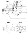
- Figure 1 shows a first embodiment of the present invention,
- Figure 2 shows part of a perforated roll used in the apparatus shown in Figure 1, extended in a plane,
- Figure 3 shows a variant of Figure 2,
- Figure 4 shows a first variant of Figure 1, and
- Figure 5 shows a second variant of Figure 1.
-
- In the embodiment shown in Figure 1, a web of synthetic thermoplastic fibres such as polypropylene, polyester or polyamide fibres, which is produced by carding in known manner, is supplied on a conveyor belt, indicated 1, that is impermeable to air.
- A return roll of the belt 1 is indicated 2; the web leaves the belt in the region of this return roll in order to be fed - in the manner which will be described below - between the two heated
rolls 3, 4 of a calender which bonds the web thermally. - Preferably, the
first roll 3, which is the first roll with which the web comes into contact, is knurled, whereas the second roll 4 is smooth. The fibres of the web are welded together at points, in known manner, as a result of their passage between the tworolls 3 and 4. - The
bonded web 5 emerging from the calender 1 is intended for use in the production of non-woven fabrics. - The axes of the two calender rolls 3, 4 lie in a horizontal plane and the tops of the rolls are situated slightly below a horizontal plane tangential to the top of the
return roll 2. - A perforated pressure roll 6, constituted by a hollow roll having holes in its surface, acts on the web transported by the belt 1, upstream of the
return roll 2. - The roll 6 compresses the web, reducing its thickness and thus bonding together the two or more webs of which it is composed. The holes provided in the surface of the roll 6 enable the air expelled from the web 1 as a result of its compression by the roll 6 to be discharged into the cavity inside the roll 6, which is in communication with the external atmosphere.
- A perforated following roll 7, interposed between the
return roll 2 of the conveyor belt 1 and thefirst calender roll 3, is almost in contact with both of therolls - The following roll 7 exerts a pressure on the web in order to cause it to adhere to the
first calender roll 3 at a point situated in the vicinity of the top of theroll 3. A portion of the roll 7 extends below a horizontal plane tangential to thereturn roll 2 so that the roll 7 forces the web to form a loop on its path between therolls roll 3 without folds. The roll 7 also helps to discharge the air still contained in the web into the interior of the roll. - As shown in Figure 2, the surface of the roll 7 preferably has elongate holes 8 extending transversely relative to the direction F of the movement of the web on the conveyor belt 1 and arranged in rows which are parallel to the axis of rotation and are spaced apart uniformly, the holes of each row being offset relative to the holes of the two adjacent rows.
By way of example, the holes 8 may have a length of 15 mm and a width of 5 mm and the holes of each row may be spaced apart by 10 mm. - In the variant of Figure 3, the elongate holes, indicated 8a, are inclined to the axis of rotation of the roll 7 alternately in opposite directions relative to the direction F of advance of the web. The axis of each
hole 8a is preferably inclined at an angle of between 30 and 45° to the axis of rotation of the roll 7. - According to variants, not shown, the holes may have a circular or polygonal outline, or the surface of the roll 7 may be constituted by a metal mesh.
- A first cylindrical screen, indicated 9, faces the surface of the
roll 3 remote from that which faces the roll 4. - As a result of the rotation of the
roll 3, the screen 9 produces a laminar air-jet directed towards the region in which the distance between theroll 3 and the overlying following roll 7 is shortest. This air-jet, which is discharged through the holes in the roll 7, directs and compresses the web in a uniform manner so that it is possible to operate with a very limited stretch, avoiding the disadvantages connected with a large amount of stretch. - The screen 9 is supported by a fixed,
hollow body 10 containing a fluid which is circulated, by means of apump 11, in a circuit including anintake duct 12, aheat exchanger 13, and adelivery duct 14. This screen 9, and consequently the air directed thereby, are thus kept at a moderate temperature such as not to damage the web. - A
second screen 15 with a cylindrical profile faces the surface of theroll 3 disposed between the perforated following roll 7 and the region of contact between thecalender rolls 3 and 4. - As a result of the rotation of the
roll 3, thescreen 15 produces a laminar air-jet which directs and compresses the web onto this surface of theroll 3 in a uniform manner. This prevents the ascending high-temperature air turbulence which would otherwise arise in the upper space between the tworolls 3 and 4 as a result of their rotation in opposite directions and the consequent damage to the web in the form of blisters, breakages, buckling and striation. - The
screen 15 is supported by a fixed,hollow body 16 containing a fluid which is circulated by means of apump 17 in a circuit which comprises anintake duct 18, aheat exchanger 19, and adelivery duct 20. - The advantages of the above-described web-bonding apparatus lie in the fact that it enables the air contained in the web to be discharged in a manner such as to bring about preliminary bonding of the fibres and to improve the adhesion of the web to the first calender roll.
- Moreover, in this apparatus, the speed of the conveyor belt and the speeds of the perforated rolls and of the calender rolls are not linked to one another so that it is possible to take full advantage of the good cohesion characteristics of the carded fibres, controlling the degree of stretch as required, which enables the production speed to be increased without changing the toughness value or the degree of isotropy of the product.
- In the first variant of Figure 1, which is shown in Figure 4, corresponding parts are indicated by the same reference numerals increased by 100.
- This variant differs from the embodiment shown in Figure 1 in that the axes of the
calender rolls 103 and 104 (which are arranged, as in Figure 1, below the horizontal plane in which the active pass of theconveyor belt 201 lies) lie in a vertical plane. - The top of the
first calender roll 103 is tangential to the above-mentioned horizontal plane and the lower surface of the perforated followingroll 107 extends below this plane so that, as in the embodiment of Figure 1, a loop is formed, causing the web to adhere to theroll 103, conferring a limited tension on the web. The functions of theperforated pressure roll 106, of the perforated followingroll 107, and of thescreens - In the second variant of Figure 1 which is shown in Figure 5, corresponding parts are indicated by the same reference numerals increased by 200.
- In this variant, the perforated pressure roll, indicated 6 in Figure 1 and 106 in Figure 4, has been omitted and the axes of the
rolls - The perforated following
roll 207 is disposed above thereturn roll 202 so that it also acts as a pressure roll for discharging the air from the web on its path between the point of contact A between therolls rolls - Although reference is made in the foregoing description to apparatus for the bonding by calendering of a web of fibres produced by carding, the invention may also advantageously be applied to a web produced by extrusion, that is, when the well-known method known as "spun-bonding" is used.
Claims (10)
- Apparatus for the production of thermally bonded non-woven fabric, in which a web of fibres produced by carding or extrusion by the "spun-bonding" method is supplied, by means of a conveyor belt impermeable to air, to a calender comprising a pair of heated rolls, characterized in that it comprises:a first screen with a cylindrical profile (9, 109, 209) which faces a portion of the surface of the first calender roll (3, 103, 203) and, as a result of the rotation of this roll, produces a laminar air-jet directed towards the region in which the web contacts the first calender roll, anda second screen with a cylindrical profile (15, 115, 215) which faces the surface of the first calender roll (3, 103, 203) that is adjacent to the region of contact between the two calender rolls (3, 103, 203; 4, 104, 204) and, as a result of the rotation of the first roll, produces a laminar air-jet which directs and compresses the web in a uniform manner onto the said surface of the first roll (3, 103, 203).
- Apparatus according to Claim 1, characterized in that it also comprises a hollow following roll (7, 107, 207) having a perforated surface which acts on the web on its path between the conveyor belt (1, 101, 201) and the first calender roll (3, 103, 203) in a manner such as to exert on the web a slight pressure which promotes the adhesion of the web to the first roll and causes the air contained in the web to be discharged into the interior of the following roll (7, 107, 207).
- Apparatus according to Claim 1, characterized in that it also comprises a hollow pressure roll (6, 106, 206) having a perforated surface which acts on the web transported by the conveyor belt (1, 101, 201), upstream of a return roll (2, 102, 202) in the vicinity of which the web leaves the conveyor belt, so as to compress the web, reducing its thickness and bonding the webs of which it is composed, the air expelled from the web as a result of this compression being discharged into the interior of the hollow pressure roll (6, 106, 206) through holes (8, 8a) in its surface.
- Apparatus according to Claim 1, characterized in that cooling means are provided for cooling each of the above-mentioned two cylindrical screens (9, 109, 209; 15, 115, 215).
- Apparatus according to Claim 3, characterized in that each cylindrical screen (9, 109, 209; 15, 115, 215) is supported by a hollow body (10, 110, 210; 16, 116, 216) containing a coolant fluid which is circulated in a circuit comprising a heat exchanger (13, 113, 213; 19, 119, 219).
- Apparatus according to Claim 1, characterized in that the holes in the hollow following roll (7, 107, 207) are constituted by elongate holes (8) extending transversely relative to the direction of movement of the web.
- Apparatus according to Claim 1, characterized in that the holes in the hollow following roll (7, 107, 207) are constituted by elongate holes (8a) inclined to the axis of rotation of the roll and extending alternately in opposite directions relative to the direction of movement of the web.
- Apparatus according to Claim 1, characterized in that the two calender rolls (3, 4) have their axes lying in a substantially horizontal plane and are disposed below the horizontal plane in which the active pass of the conveyor (1, 101) lies.
- Apparatus according to Claim 1, characterized in that the two calender rolls have their axes lying in a substantially vertical plane and are disposed below the substantially horizontal plane in which the active pass of the conveyor lies.
- Apparatus according to Claim 1, characterized in that the two calender rolls (203, 204) have their axes lying in a substantially vertical plane and are disposed above the substantially horizontal plane in which the active pass of the conveyor lies.
Applications Claiming Priority (2)
| Application Number | Priority Date | Filing Date | Title |
|---|---|---|---|
| ITTO010039 | 2001-01-19 | ||
| IT2001TO000039A ITTO20010039A1 (en) | 2001-01-19 | 2001-01-19 | EQUIPMENT FOR THE PRODUCTION OF NON-WOVEN FABRIC THERMALLY COHESIONED BY CALENDERING. |
Publications (1)
| Publication Number | Publication Date |
|---|---|
| EP1225264A1 true EP1225264A1 (en) | 2002-07-24 |
Family
ID=11458406
Family Applications (1)
| Application Number | Title | Priority Date | Filing Date |
|---|---|---|---|
| EP02000922A Withdrawn EP1225264A1 (en) | 2001-01-19 | 2002-01-16 | Apparatus for the production of non-woven fabric thermally bonded by calendering |
Country Status (2)
| Country | Link |
|---|---|
| EP (1) | EP1225264A1 (en) |
| IT (1) | ITTO20010039A1 (en) |
Citations (9)
| Publication number | Priority date | Publication date | Assignee | Title |
|---|---|---|---|---|
| DE2639447A1 (en) * | 1976-09-02 | 1978-03-16 | Reifenhaeuser Kg | Roller system for shaping thermoplastics extrudate into a sheet - comprises stationary roller frame with feed-in roller and counter roller and swivelable roller frame with treating roller |
| US4324613A (en) * | 1978-03-31 | 1982-04-13 | Douglas Wahren | Methods and apparatus for the rapid consolidation of moist porous webs |
| US4589167A (en) * | 1984-03-22 | 1986-05-20 | Spinnbau Gmbh | Apparatus for introducing a pile into a following roller system |
| US4605366A (en) * | 1983-02-10 | 1986-08-12 | Sulzer-Escher Wyss Ag | Calender for pressure and thermal treatment of material webs |
| US4610617A (en) * | 1983-02-10 | 1986-09-09 | Sulzer-Escher Wyss Ag | Heat insulating protective shields for two-roll calender with heated rolls |
| DE9408597U1 (en) * | 1994-05-25 | 1995-09-28 | Eduard Küsters Maschinenfabrik GmbH & Co. KG, 40239 Düsseldorf | Fleece calender |
| WO1998038382A1 (en) * | 1997-02-28 | 1998-09-03 | Valmet Corporation | Method and device in calender in threading of paper |
| EP0899370A2 (en) * | 1997-08-28 | 1999-03-03 | Spinnbau GmbH | Calender rolls for fleece |
| US6050469A (en) * | 1995-03-22 | 2000-04-18 | Thibeau Et Cie | Suction cylinder which transfers fiber web from a conveyer belt to two calendering cylinders |
-
2001
- 2001-01-19 IT IT2001TO000039A patent/ITTO20010039A1/en unknown
-
2002
- 2002-01-16 EP EP02000922A patent/EP1225264A1/en not_active Withdrawn
Patent Citations (9)
| Publication number | Priority date | Publication date | Assignee | Title |
|---|---|---|---|---|
| DE2639447A1 (en) * | 1976-09-02 | 1978-03-16 | Reifenhaeuser Kg | Roller system for shaping thermoplastics extrudate into a sheet - comprises stationary roller frame with feed-in roller and counter roller and swivelable roller frame with treating roller |
| US4324613A (en) * | 1978-03-31 | 1982-04-13 | Douglas Wahren | Methods and apparatus for the rapid consolidation of moist porous webs |
| US4605366A (en) * | 1983-02-10 | 1986-08-12 | Sulzer-Escher Wyss Ag | Calender for pressure and thermal treatment of material webs |
| US4610617A (en) * | 1983-02-10 | 1986-09-09 | Sulzer-Escher Wyss Ag | Heat insulating protective shields for two-roll calender with heated rolls |
| US4589167A (en) * | 1984-03-22 | 1986-05-20 | Spinnbau Gmbh | Apparatus for introducing a pile into a following roller system |
| DE9408597U1 (en) * | 1994-05-25 | 1995-09-28 | Eduard Küsters Maschinenfabrik GmbH & Co. KG, 40239 Düsseldorf | Fleece calender |
| US6050469A (en) * | 1995-03-22 | 2000-04-18 | Thibeau Et Cie | Suction cylinder which transfers fiber web from a conveyer belt to two calendering cylinders |
| WO1998038382A1 (en) * | 1997-02-28 | 1998-09-03 | Valmet Corporation | Method and device in calender in threading of paper |
| EP0899370A2 (en) * | 1997-08-28 | 1999-03-03 | Spinnbau GmbH | Calender rolls for fleece |
Also Published As
| Publication number | Publication date |
|---|---|
| ITTO20010039A1 (en) | 2002-07-19 |
| ITTO20010039A0 (en) | 2001-01-19 |
Similar Documents
| Publication | Publication Date | Title |
|---|---|---|
| US6050469A (en) | Suction cylinder which transfers fiber web from a conveyer belt to two calendering cylinders | |
| JP5008589B2 (en) | Method and apparatus for producing spunbond nonwovens | |
| EP1170411B1 (en) | Apparatus for making nonwoven fabric | |
| JP2012207363A (en) | Patterning on sms product | |
| ITMI991468A1 (en) | DEVICE TO CONDENSATE AN IRON FIBER COMPLEX | |
| US20130078368A1 (en) | Fabric comprising shaped conductive monofilament used in the production of non-woven fabrics | |
| EP1225264A1 (en) | Apparatus for the production of non-woven fabric thermally bonded by calendering | |
| EP3792384B1 (en) | Industrial fabric | |
| KR20060121727A (en) | Method and apparatus for manufacturing spunbond fabric | |
| KR100572161B1 (en) | Method and apparatus for making nonwoven web or fleece from synthetic resin strands | |
| JP2002285433A (en) | Spinning machine with multiple adjacently arranged spinning stations | |
| KR100477859B1 (en) | Membrane Support of Polyester Nonwoven Fabric | |
| US7610659B2 (en) | Apparatus and method for making a polymer fill | |
| JP3173911B2 (en) | Manufacturing method of long fiber non-woven fabric | |
| CN1869307B (en) | Method and device for manufacturing spunbonded fabric | |
| JP2021090692A (en) | Method of manufacturing nonwoven fabric | |
| JP2021070874A (en) | Apparatus for manufacturing nonwoven fabric and method for manufacturing nonwoven fabric | |
| AU3435402A (en) | Apparatus for making web including continuous fibers | |
| JP3280753B2 (en) | Nonwoven fabric manufacturing method and device | |
| JP2003127261A (en) | Cloth and pleated products suitable for pleating | |
| JPS5810505B2 (en) | Heat forming equipment for nonwoven fabric production | |
| CN1951790A (en) | Electrostatically chucking of a web of non-woven fabric in contact with an overlying surface | |
| JP2021025187A (en) | Apparatus and method for producing nonwoven fabric from fibers | |
| JP2020121289A (en) | Network structure for dust collection | |
| JP2021066976A (en) | Emboss processing apparatus and method for producing nonwoven fabric |
Legal Events
| Date | Code | Title | Description |
|---|---|---|---|
| PUAI | Public reference made under article 153(3) epc to a published international application that has entered the european phase |
Free format text: ORIGINAL CODE: 0009012 |
|
| AK | Designated contracting states |
Kind code of ref document: A1 Designated state(s): AT BE CH CY DE DK ES FI FR GB GR IE IT LI LU MC NL PT SE TR |
|
| AX | Request for extension of the european patent |
Free format text: AL;LT;LV;MK;RO;SI |
|
| 17P | Request for examination filed |
Effective date: 20030115 |
|
| AKX | Designation fees paid |
Designated state(s): BE DE ES FR GB IT |
|
| STAA | Information on the status of an ep patent application or granted ep patent |
Free format text: STATUS: THE APPLICATION IS DEEMED TO BE WITHDRAWN |
|
| 18D | Application deemed to be withdrawn |
Effective date: 20040802 |