EP1224860A2 - Trinkventil - Google Patents
Trinkventil Download PDFInfo
- Publication number
- EP1224860A2 EP1224860A2 EP01204673A EP01204673A EP1224860A2 EP 1224860 A2 EP1224860 A2 EP 1224860A2 EP 01204673 A EP01204673 A EP 01204673A EP 01204673 A EP01204673 A EP 01204673A EP 1224860 A2 EP1224860 A2 EP 1224860A2
- Authority
- EP
- European Patent Office
- Prior art keywords
- valve
- drinking
- guide member
- movement
- guide
- Prior art date
- Legal status (The legal status is an assumption and is not a legal conclusion. Google has not performed a legal analysis and makes no representation as to the accuracy of the status listed.)
- Withdrawn
Links
Images


Classifications
-
- A—HUMAN NECESSITIES
- A01—AGRICULTURE; FORESTRY; ANIMAL HUSBANDRY; HUNTING; TRAPPING; FISHING
- A01K—ANIMAL HUSBANDRY; AVICULTURE; APICULTURE; PISCICULTURE; FISHING; REARING OR BREEDING ANIMALS, NOT OTHERWISE PROVIDED FOR; NEW BREEDS OF ANIMALS
- A01K7/00—Watering equipment for stock or game
- A01K7/02—Automatic devices
- A01K7/06—Automatic devices actuated by the animal
Definitions
- the present invention relates to a drinking valve of the "bite valve” type for animals, comprising a valve head with a connection to a water conduit, an openable valve cone and an externally accessible actuator which is movably secured to the drinking valve, the valve cone being displaceable reciprocally between a closed position and an open position.
- valves Numerous types of waterer valves are previously known in the art for use in animal stalls and the like.
- One important such type of valve is the so-called bite valve.
- These valves lack a receptacle for the outflowing water, such as a cup, and so the animals drink straight out of the valve.
- the valve is actuated, i.e. it is opened so that water can flow out, by the animal's acting on an actuator device with its mouth and teeth, the device being disposed on the valve. Actuation takes place at the same time as the drinking animal has the outlet of the valve in its mouth.
- the actuator device When the animal releases the actuator device, the valve closes and the water flow thereby ceases.
- bite valves that are available on the market are provided with an operating rod which extends in the longitudinal direction of the valve and which is connected to a valve plate which, under spring force and water pressure, is held pressed against the seat of the valve when the valve is closed.
- the operating rod opens the valve when it is rocked transversely of its longitudinal direction.
- the operating rod is either actuated directly, in that it is made accessible to the animal, or via a pin which is connected to an actuator which in turn is disposed outside the bite valve.
- bite valves are often associated with a number of drawbacks.
- the valves are subjected to extreme wear, not least because of the rough treatment to which they are subjected by the animals.
- Another problem is that water which flows out through the valve is not always of the best quality. The water often comes from a separate well and is not subjected to any purification before being fed through the valves. Such water may be hard, acidic, sandy or otherwise contaminated or aggressive.
- bite valves wear out quickly, and depositions readily accumulate in them. Each one of these factors may impede the return of the valve to the closed position, which implies that the valve rapidly begins to leak.
- a method of attempting to remedy the leakage problem is to increase the pressure of the valve cone against its valve seat by, for instance, providing a spring or alternatively replacing an existing spring with a more powerful one.
- this mode of approach entails greater wear on the valve, for which reason the above-mentioned problems rapidly recur.
- valve cone executes a linear movement. This avoids wear occurring locally on the gasket, but the prior art drinking valves utilise a lever for realising the linear movement of the operating rod. Given that the connection between the actuator and the valve cone must take place in several stages which utilise moving parts, the risk of valve failure is quite great.
- the actuator has a guide member which is movably disposed in a guide in the drinking valve in order, on displacement, to execute a movement, and that the guide member is simultaneously disposed for direct or indirect action on the valve cone between its closed and its open position, or vice versa, in such a movement.
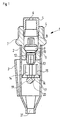
- Fig. 1 shows a drinking valve of the "bite valve” type for animals, according to the present invention.
- the valve is here located in its closed position.
- the valve has three major sections: viz. a valve head 1, an outer casing 2 and an actuator 3.
- the valve head 1 is disposed to be connected to a water conduit and is therefore provided with threading 4.
- the outer casing 2 surrounds the greater part of the valve and has, in its lower end, an outlet 21.
- an actuator 3 is disposed on the outside of the outer casing.
- the actuator 3 is acted on by the animals when they bite around it with their lips and/or teeth. When this happens, the actuator will in turn open the valve.
- valve head is provided with threading 4 so that it can be connected to a water conduit.
- throttle 5 for restricting the water flow.
- the aperture 6 of the throttle 5 may be of different sizes, depending upon the flow which is desired and the pressure which prevails in the water conduit. The desirable flow is in its turn determined by what species of animal it is intended will use the valve.
- a filter (not shown) is disposed which preferably consists of a grid or fine mesh net.
- the filter prevents coarse foreign matter from entering into the interior of the valve and causing damage there.
- a spring (not shown) is disposed below the filter. The spring biases the valve towards its closed position.
- a valve housing 7 is disposed in the lower end of the valve head 1.
- a cavity 8 in which a valve cone 9 is disposed.
- the valve cone 9 has a valve plate 10 which is provided with a gasket where it is intended to abut against the valve seat 11.
- the gasket is relatively soft and seals tightly.
- the use of such a gasket is possible from the point of view of wear, since the gasket and the valve plate 10 together execute a linear movement in relation to the valve seat 11.
- the abutment surface of the gasket against the valve seat is relatively large and uniformly distributed throughout the entire gasket. In principle, no point loading occurs.
- a channel 12 through which a spindle 13 extends.
- a spindle 13 there is a certain clearance between the walls of the channel 12 and the outer contour of the spindle 13 so that water may flow therebetween when the valve cone is located in its open position, which is shown in Fig. 2.
- the outer casing 2 is elongate and substantially tubular.
- the tube has the outer contour of a cylinder.
- the valve housing 7 extends a distance into the upper region of the outer casing 2.
- a distributor member 14 is disposed below the spindle 13 and in contact with it (inside the outer casing 2). When water flows through the valve, it meets the distributor member 14 which is operative to split up the water jet and lead it outwards towards the inner walls of the outer casing 2. The water jet is thereby broken up and the water becomes more comfortable for the animals to drink.
- the distributor member 14 is, to this end, provided with upright vanes 15 on a lower plate 16.
- the plate 16 has an outer contour which largely corresponds to the inner contour of the outer casing 2. However, there is a certain clearance between the outer contour of the distributor member 14 and the inner walls of the outer casing 2, so that water can flow between them.
- the edge 18 of the plate 16 is moreover provided with a number of recesses 17.
- the recesses 17 facilitate the flow of the water and possibly aerate the water.
- the distributor member 14 and its parts are clearly apparent from Fig. 3.
- the distributor member 14 abuts against the spindle 13 which in turn executes linear movements to the valve cone 9. In order to realise linear movements in the longitudinal direction of the valve, the distributor member 14 must thus be acted on.
- a guide member 19 In order to move from the closed position illustrated in Fig. 1 to the open position illustrated in Fig. 2, a guide member 19 must act on the distributor member 14 with an upwardly directed movement. The movement of the guide member 19 is realised with the aid of the actuator 3.
- the actuator 3 is disposed outside the outer casing 2 and wholly or partly surrounds it.
- the actuator 3 is secured to the outer casing 2 with the aid of the guide member 19 which, in the preferred embodiment, is a pin extending at least a distance into the outer casing 2 for retention of the actuator 3 there.
- the guide member or pin 19 is disposed to be movable in a guide 20 which, in the preferred embodiment, consists of a slot in the outer casing 2.
- the guide member 19 movably interconnects the actuator 3 with the outer casing 2, it also abuts against the distributor member 14.
- the guide member or pin 19 abuts against the underside of the plate 16 of the distributor member 14. This is particularly advantageous if the pin 19 is through-going so that the abutment against the underside of the plate 16 is linear. If the pin 19 is moved upwards, regardless of being simultaneously moved sideways, the distributor member 14 is also forced upwards. In such instance, the pin 19 may execute a sliding movement along the plate 16. When the pin 19 is no longer affected by any force from the actuator, the distributor member 14 will return the pin 19 to the original position in Fig. 1 with the aid of the water pressure and the spring disposed in the valve.
- the guide or slot 20 has a longitudinal direction which makes an angle with the direction of movement of the valve cone 9 which, in the illustrated embodiment, corresponds to the longitudinal direction of the valve.
- the movement réelle which is parallel with the direction of movement of the valve cone 9 may, in the preferred embodiment, also be called longitudinal, while the second movement réelle may be called transverse.
- a major advantage in the present invention is that, regardless of how the force is applied on the actuator 3, i.e. regardless of how the animal bites, the guide member will be given an upwardly directed movement réelle. Consequently, the valve will be more operationally reliable and less sensitive to rough treatment.
- the slot is straight and makes an angle with the longitudinal direction of the valve cone 9.
- One alternative is to cause the guide or slot 20 to be curved.
- the guide member 19 then executes a curved movement when the actuator 3 is pressed against the outer casing 2.
- the ceremonies of the movement can be divided up and its longitudinal ceremonies thereby varies.
- the ratio between the force applied on the actuator 3 and the force with which the guide member 19 acts on the distributor member which in turn opens the valve cone 9 will thus vary during the movement.
- the ratio and thereby the local angle of the slot should be adapted to this in order that the force by which the actuator 3 is to be acted on is reasonable for the animal.
- Another method of utilising the configuration and angling of the slot is to adapt it to different suction and drinking behaviour patterns in different breeds of animal. It is quite simple to imagine that the behaviour of a piglet is different from the behaviour of a fully-grown bull. There may therefore be a need for several different variations of the drinking valve according to the present invention.
Landscapes
- Life Sciences & Earth Sciences (AREA)
- Environmental Sciences (AREA)
- Animal Husbandry (AREA)
- Biodiversity & Conservation Biology (AREA)
- Lift Valve (AREA)
- Mechanically-Actuated Valves (AREA)
- Feeding And Watering For Cattle Raising And Animal Husbandry (AREA)
- Multiple-Way Valves (AREA)
Applications Claiming Priority (2)
| Application Number | Priority Date | Filing Date | Title |
|---|---|---|---|
| SE0004758A SE518064C2 (sv) | 2000-12-20 | 2000-12-20 | Dryckesventil |
| SE0004758 | 2000-12-20 |
Publications (2)
| Publication Number | Publication Date |
|---|---|
| EP1224860A2 true EP1224860A2 (de) | 2002-07-24 |
| EP1224860A3 EP1224860A3 (de) | 2003-10-01 |
Family
ID=20282340
Family Applications (1)
| Application Number | Title | Priority Date | Filing Date |
|---|---|---|---|
| EP01204673A Withdrawn EP1224860A3 (de) | 2000-12-20 | 2001-12-04 | Trinkventil |
Country Status (2)
| Country | Link |
|---|---|
| EP (1) | EP1224860A3 (de) |
| SE (1) | SE518064C2 (de) |
Cited By (1)
| Publication number | Priority date | Publication date | Assignee | Title |
|---|---|---|---|---|
| WO2022261551A1 (en) * | 2021-06-11 | 2022-12-15 | Boa Nutrition, Inc. | Hands-free electrolyte dispenser |
Family Cites Families (2)
| Publication number | Priority date | Publication date | Assignee | Title |
|---|---|---|---|---|
| FR2123327B1 (de) * | 1971-01-26 | 1975-06-13 | Be | |
| DE8101597U1 (de) * | 1981-01-23 | 1982-02-11 | Suevia Haiges GmbH & Co, 7125 Kirchheim | Traenkzapfen fuer tiere |
-
2000
- 2000-12-20 SE SE0004758A patent/SE518064C2/sv not_active IP Right Cessation
-
2001
- 2001-12-04 EP EP01204673A patent/EP1224860A3/de not_active Withdrawn
Cited By (1)
| Publication number | Priority date | Publication date | Assignee | Title |
|---|---|---|---|---|
| WO2022261551A1 (en) * | 2021-06-11 | 2022-12-15 | Boa Nutrition, Inc. | Hands-free electrolyte dispenser |
Also Published As
| Publication number | Publication date |
|---|---|
| EP1224860A3 (de) | 2003-10-01 |
| SE0004758L (sv) | 2002-06-21 |
| SE0004758D0 (sv) | 2000-12-20 |
| SE518064C2 (sv) | 2002-08-20 |
Similar Documents
| Publication | Publication Date | Title |
|---|---|---|
| CA2170630C (en) | A device and a method for blocking a liquid flow through a pipe in one direction | |
| US4477051A (en) | Flow control valve | |
| CA1043646A (en) | Valve | |
| US20140144516A1 (en) | Fire hydrant control valve | |
| DE4009129A1 (de) | Spuelventilgriffanordnung | |
| US5924678A (en) | Bite-valve | |
| US4633816A (en) | Device for controlled discharge of liquid to animals | |
| EP1224860A2 (de) | Trinkventil | |
| DE2147027A1 (de) | Vorrichtung zur regelung der temperatur der ansaugluft von gemischverdichtenden brennkraftmaschinen | |
| JP2000505181A (ja) | 切換弁 | |
| US5522346A (en) | Low toggle force poultry watering valve | |
| US9743642B2 (en) | Animal watering apparatus | |
| US20020108894A1 (en) | Mechanical oil filtration in an i.c. engine valve lifter | |
| DE3901224A1 (de) | Wassermischventil mit zeitlich festgelegter absperrung | |
| CA2140728C (en) | Nipple waterer substitute compression element | |
| DE102005039330A1 (de) | Luftstromsteuerventil zum Gebrauch in einer Brennkraftmaschine | |
| ATE142843T1 (de) | Kleintiertränkeventil | |
| EP1347104B1 (de) | Wasserauslassventil | |
| CA1318305C (en) | Remotely actuated, reversible drain valve | |
| US3964510A (en) | Live well valve | |
| AU2012216270B2 (en) | Liquid control valve | |
| US6085721A (en) | Bar engine brake | |
| JPH0523646Y2 (de) | ||
| JPH0444945Y2 (de) | ||
| WO2025202096A1 (de) | VERTIKALER RÜCKSTAUVERSCHLUSS MIT AUSLASSSEITIG ABGESCHIRMTER VENTILSTÖßELFÜHRUNG |
Legal Events
| Date | Code | Title | Description |
|---|---|---|---|
| PUAI | Public reference made under article 153(3) epc to a published international application that has entered the european phase |
Free format text: ORIGINAL CODE: 0009012 |
|
| AK | Designated contracting states |
Kind code of ref document: A2 Designated state(s): AT BE CH CY DE DK ES FI FR GB GR IE IT LI LU MC NL PT SE TR |
|
| AX | Request for extension of the european patent |
Free format text: AL;LT;LV;MK;RO;SI |
|
| PUAL | Search report despatched |
Free format text: ORIGINAL CODE: 0009013 |
|
| AK | Designated contracting states |
Kind code of ref document: A3 Designated state(s): AT BE CH CY DE DK ES FI FR GB GR IE IT LI LU MC NL PT SE TR |
|
| AX | Request for extension of the european patent |
Extension state: AL LT LV MK RO SI |
|
| RIC1 | Information provided on ipc code assigned before grant |
Ipc: 7A 01K 7/06 B Ipc: 7A 01K 7/00 A |
|
| AKX | Designation fees paid | ||
| REG | Reference to a national code |
Ref country code: DE Ref legal event code: 8566 |
|
| STAA | Information on the status of an ep patent application or granted ep patent |
Free format text: STATUS: THE APPLICATION IS DEEMED TO BE WITHDRAWN |
|
| 18D | Application deemed to be withdrawn |
Effective date: 20040402 |