EP1224763B1 - Method and apparatus for communicating a call - Google Patents
Method and apparatus for communicating a call Download PDFInfo
- Publication number
- EP1224763B1 EP1224763B1 EP00965168A EP00965168A EP1224763B1 EP 1224763 B1 EP1224763 B1 EP 1224763B1 EP 00965168 A EP00965168 A EP 00965168A EP 00965168 A EP00965168 A EP 00965168A EP 1224763 B1 EP1224763 B1 EP 1224763B1
- Authority
- EP
- European Patent Office
- Prior art keywords
- bit stream
- call
- calls
- channel
- wireless communication
- Prior art date
- Legal status (The legal status is an assumption and is not a legal conclusion. Google has not performed a legal analysis and makes no representation as to the accuracy of the status listed.)
- Expired - Lifetime
Links
- 238000000034 method Methods 0.000 title claims abstract description 45
- 238000004891 communication Methods 0.000 claims abstract description 145
- 230000005540 biological transmission Effects 0.000 abstract description 10
- 230000008569 process Effects 0.000 abstract description 7
- 238000010586 diagram Methods 0.000 description 12
- 230000001413 cellular effect Effects 0.000 description 6
- 230000006870 function Effects 0.000 description 5
- 230000004044 response Effects 0.000 description 5
- 230000006735 deficit Effects 0.000 description 2
- 230000003993 interaction Effects 0.000 description 2
- 241000284156 Clerodendrum quadriloculare Species 0.000 description 1
- 230000004913 activation Effects 0.000 description 1
- 239000000969 carrier Substances 0.000 description 1
- 230000001427 coherent effect Effects 0.000 description 1
- 239000004020 conductor Substances 0.000 description 1
- 238000011217 control strategy Methods 0.000 description 1
- 230000002596 correlated effect Effects 0.000 description 1
- 238000005562 fading Methods 0.000 description 1
- 230000006872 improvement Effects 0.000 description 1
- 230000000977 initiatory effect Effects 0.000 description 1
- 239000004973 liquid crystal related substance Substances 0.000 description 1
- 230000007246 mechanism Effects 0.000 description 1
- 230000003287 optical effect Effects 0.000 description 1
- 238000005457 optimization Methods 0.000 description 1
- 230000002093 peripheral effect Effects 0.000 description 1
- 230000010363 phase shift Effects 0.000 description 1
- 230000009467 reduction Effects 0.000 description 1
- 230000000717 retained effect Effects 0.000 description 1
- 230000005236 sound signal Effects 0.000 description 1
- 238000001228 spectrum Methods 0.000 description 1
- 230000000007 visual effect Effects 0.000 description 1
Images


Classifications
-
- H—ELECTRICITY
- H04—ELECTRIC COMMUNICATION TECHNIQUE
- H04L—TRANSMISSION OF DIGITAL INFORMATION, e.g. TELEGRAPHIC COMMUNICATION
- H04L1/00—Arrangements for detecting or preventing errors in the information received
- H04L1/004—Arrangements for detecting or preventing errors in the information received by using forward error control
- H04L1/0056—Systems characterized by the type of code used
- H04L1/0071—Use of interleaving
-
- H—ELECTRICITY
- H04—ELECTRIC COMMUNICATION TECHNIQUE
- H04L—TRANSMISSION OF DIGITAL INFORMATION, e.g. TELEGRAPHIC COMMUNICATION
- H04L1/00—Arrangements for detecting or preventing errors in the information received
- H04L1/0001—Systems modifying transmission characteristics according to link quality, e.g. power backoff
- H04L1/0002—Systems modifying transmission characteristics according to link quality, e.g. power backoff by adapting the transmission rate
- H04L1/0003—Systems modifying transmission characteristics according to link quality, e.g. power backoff by adapting the transmission rate by switching between different modulation schemes
-
- H—ELECTRICITY
- H04—ELECTRIC COMMUNICATION TECHNIQUE
- H04L—TRANSMISSION OF DIGITAL INFORMATION, e.g. TELEGRAPHIC COMMUNICATION
- H04L27/00—Modulated-carrier systems
- H04L27/32—Carrier systems characterised by combinations of two or more of the types covered by groups H04L27/02, H04L27/10, H04L27/18 or H04L27/26
- H04L27/34—Amplitude- and phase-modulated carrier systems, e.g. quadrature-amplitude modulated carrier systems
-
- H—ELECTRICITY
- H04—ELECTRIC COMMUNICATION TECHNIQUE
- H04L—TRANSMISSION OF DIGITAL INFORMATION, e.g. TELEGRAPHIC COMMUNICATION
- H04L5/00—Arrangements affording multiple use of the transmission path
- H04L5/02—Channels characterised by the type of signal
- H04L5/12—Channels characterised by the type of signal the signals being represented by different phase modulations of a single carrier
Definitions
- This invention relates in general to wireless communication systems and in particular to the communication of calls within a wireless communication system.
- Wireless communication systems today employ a variety of modulation schemes from analog modulation to digital modulation such as binary phase modulation and binary frequency modulation.
- the type of modulation utilized greatly affects the performance, of the wireless communication system. Considerable effort is spent in the optimization of key performance elements such as bandwidth, demodulator performance and error control strategy for overall enhancement of data throughput.
- QAM quadrature amplitude modulation
- QAM is the amplitude modulation and demodulation of two carriers that have the same frequency but are in phase quadrature to each other. It can be either analog or digital. QAM has been shown to be a suitable modulation scheme for wireless communication systems.
- variable rate QAM modulation has been found to be an efficient modulation scheme capable of substantial performance gains over conventional QAM.
- the wireless communication device and the base station transmitter coordinate to determine an optimum modulation rate based on signal conditions and channel loading.
- the baud rate in such a system is fixed, but multiple modulation levels are allowed (2QAM, 4QAM, 16QAM etc.).
- QAM transmissions over wireless communication channels are subject to a variety of impairments, including interference, noise, multipath fading, and delay spread. In general, higher modulation levels (16 QAM, 64 QAM, etc.) are less tolerant to these impairments than lower modulation levels (2 QAM or 4 QAM).
- the modulation level is adapted to the existing channel conditions, usually using the highest modulation level which meets some minimum performance requirements (Bit error rate, packet loss, etc.)
- a pilot carrier can be transmitted along with the data to provide a reference for coherent demodulation.
- a pilot carrier can be transmitted along with the data to provide a reference for coherent demodulation.
- WO-A-96/19055 describes an OFDM communication system where two OFDM channels are provided on the in phase and quadrature components of each subcarrier.
- variable rate QAM modulation techniques What is needed is a method to reduce the complexity of the implementation of variable rate QAM modulation between the base station transmitters and the wireless communication devices in a wireless communication system.
- the wireless communication system 10 comprises a message input device, such as a telephone 12, a computer 14, or a desktop messaging unit 16, connected through a conventional public switched telephone network (PSTN) 18 through a plurality of conventional telephone links 20 to a system controller 22.
- PSTN public switched telephone network
- the telephone links 20 may be a plurality of twisted wire pairs, or a multiplexed trunk line.
- the system controller 22 is coupled to and oversees the operation of at least one radio frequency base transmitter 26 and, preferably, at least one radio frequency base receiver 28 through one or more communication links 24.
- the communication links 24 typically are twisted pair telephone wires, and additionally can include radio frequency (RF), microwave, or high quality audio communication links.
- the radio frequency base transmitter 26 and the radio frequency base receiver 28, which typically are message store and forward stations that encode and decode inbound and outbound telephone addresses into formats that are compatible with landline message switch computers and personal radio telephone addressing requirements, such as cellular message protocols.
- the system controller 22 can also function to encode and decode wireless messages that are transmitted to or received by the radio frequency base transmitter 26 or the radio frequency base receiver 28.
- Telephony signals are typically transmitted to and received from the system controller 22 by telephone sets such as the telephone 12 or the wireless communication device 35.
- the system controller 22 encodes and schedules outbound messages such as a downlink call 34, for transmission by the radio frequency base transmitter 26 via a transmit antenna 30 to at least one wireless communication device 35 on at least one outbound radio frequency (RF) channel 32.
- RF radio frequency
- the wireless communication device 35 may be, for example, a cellular telephone or a pager.
- the downlink call 34 may be, for example, a data message, a voice message, or a telephone call.
- the system controller 22 receives and decodes inbound messages such as an uplink call 44 received by the radio frequency base receiver 28 via a receive antenna 40 on at least one inbound RF channel 42 from the wireless communication device 35.
- the uplink call 44 may be, for example, a data message, a reply to a data message, a telephone call, or a reply to a telephone call.
- the wireless communication system 10 may function utilizing any wireless RF channel, for example, a one or two way pager channel, a mobile cellular channel, or a mobile radio channel.
- the wireless communication system 10 may function utilizing other types of channels such as infrared channels.
- the term wireless communication system refers to any of the wireless communication systems mentioned above or an equivalent.
- the wireless communication device 35 may be a mobile cellular telephone, a mobile radio data terminal, a mobile cellular telephone having an attached data terminal, or a one or two way pager.
- the term “wireless communication device” refers to any of the devices mentioned above or an equivalent.
- Each wireless communication device 35 assigned for use in the wireless communication system 10 has an address assigned thereto which is a unique selective call address in the wireless communication system 10. The address enables the transmission of the downlink call 34 from the system controller 22 only to the wireless communication device 35 having that address, and identifies the messages and responses received at the system controller 22 from the wireless communication device 35. Furthermore, each wireless communication device 35 also has a pin number assigned thereto, the pin number being associated with a telephone number within the PSTN 18. A list of the assigned addresses and correlated telephone numbers for each wireless communication device 35 is stored in the system controller 22 in the form of a subscriber database 56.
- FIG. 2 is an electrical block diagram of the system controller 22 for use in the wireless communication system 10 of FIG. 1 in accordance with the preferred embodiment of the present invention.
- the system controller 22 comprises a communication interface 46, a message handler 48, a telephone interface 50, a message memory 52, an encoder 54, the subscriber database 56, and an address circuit 58.
- the communication interface 46 queues data and stored voice messages for transmission to the wireless communication device 35, and receives acknowledgements, data responses, data messages, and telephone calls from the wireless communication device 35.
- the communication interface 46 is coupled to the radio frequency base transmitter 26 and the radio frequency base receiver 28 of FIG. 1 by the communication links 24.
- the message handler 48 which routes and processes the messages, is coupled to the communication interface 46, and is further coupled to the telephone interface 50, message memory 52, the encoder 54, and the subscriber database 56.
- the telephone interface 50 handles the PSTN 18 (see FIG. 1 ) physical connection, connecting and disconnecting telephone calls at the telephone links 20, and routing the audio signals between the telephone links 20 and the message handler 48.
- the subscriber database 56 stores information for each subscriber. This subscriber information may include a correlation between the assigned address and the telephone number used within the PSTN 18 to route messages and telephone calls to each wireless communication device 35.
- the message memory 52 stores calls and replies in queue for scheduled delivery to the wireless communication device 35.
- the encoder 54 is coupled to the message handler 48 and the address circuit 58, and encodes messages intended for transmission to the wireless communication device 35.
- the message handler 48 comprises a message processor 60, a channel manager 62, a first interleaver 64, a second interleaver 66, and a multiplexer 68.
- the message processor 60 is coupled to and interfaces with the telephone interface 50, the message memory 52, the encoder 54 and the subscriber database 56 to process the calls and the messages.
- the call processing performed by the message processor 60 includes source encoding (such as digitizing voice messages) and error correction encoding.
- the channel manager 62 is coupled between the message processor 60 and the first and second interleavers (64, 66).
- the channel manager 62 assigns the calls received from the message processor 60 to either the first interleaver 64 or the second interleaver 66 in a pre-determined manner.
- the channel manager 62 assigns the calls based on a preprogrammed algorithm.
- the calls received may include an instruction of channel assignment.
- One of ordinary skill in the art will recognize that other equivalent methods of channel assignment are within the scope of the present invention.
- the first interleaver 64 interleaves a first set of calls 70 including a first call 85 received from the channel manager 62 into an I-channel interleaving block 72.
- the data in the I-channel interleaving block 72 is then output as an I-channel bit stream 74.
- the second interleaver 66 interleaves a second set of calls 76 including a second call 87 received from the channel manager 62 into a Q-channel interleaving block 78.
- the data in the Q-channel interleaving block 78 is then output as a Q-channel bit stream 80.
- the multiplexer 68 is coupled to the first interleaver 64 and the second interleaver 66 and multiplexes the I-channel bit stream 74 received from the first interleaver 64 and the Q-channel bit stream 80 received from the second interleaver 66 into a multiplexed bit stream 82, to be described below.
- the output of the multiplexer 68 is coupled to the communication interface 46.
- the communication interface 46 Upon receipt of the multiplexed bit stream 82 from the multiplexer 68, the communication interface 46 forwards the multiplexed bit stream 82 to the radio frequency base transmitter 26 (see FIG. 1 ) through the communication links 24.
- the radio frequency base transmitter 26 generates the downlink call 34 from the multiplexed bit stream 82 for transmission to the wireless communication device 35 over the outbound RF channel 32 via the transmit antenna 30.
- the system controller 22 is preferably a EMX5000 switching terminal manufactured by Motorola Inc, of Schaumburg, Illinois, modified with firmware elements in accordance with the preferred embodiment of the present invention, as described herein.
- the communication interface 46, the message handler 48, the message memory 52, the subscriber database 56, the encoder 54, the address circuit 58, and the telephone interface 50 are preferably implemented within portions of the EMX5000 switching terminal. These portions include, but are not limited to, those portions providing program memory, a central processing unit, input/output peripherals, and a random access memory.
- the system controller 22 alternatively could be implemented using a RF-Conductor! Model 3000 series network controller manufactured by Motorola Inc. of Schaumburg, Illinois.
- the subscriber database 56 and the message memory 52 may alternatively be implemented as magnetic or optical disc memory, which may alternatively be external to the system controller 22. It will be appreciated by one of ordinary skill in the art that other similar terminals can be utilized for the system controller 22, and that additional infrastructure equipment of the same or alternative type can be added as required to handle the requirements of the system controller 22.
- system controller 22 is capable of operating in a distributed transmission control environment that allows the mixing of cellular, simulcast, master/slave, or other coverage schemes.
- a distributed transmission control environment may include a plurality of radio frequency transmitters, radio frequency receivers, transmit antennas and receive antennas for providing reliable radio signals within a geographic area as large as a nationwide network.
- the telephony and wireless communication system functions may reside in separate system controllers which operate either independently or in a networked fashion.
- FIGs. 3 through 8 illustrate one embodiment, based on linear block coding and block interleaving with three codewords per interleaving block, of the various signals generated within the system controller of FIG. 2 utilizing 4 QAM modulation.
- the system controller 22 receives two calls A and B. Call A is destined for a first wireless communication device and call B is destined for a second wireless communication device. The two calls are processed by the message processor 60 and then sent to the channel manager 62.
- the channel manager 62 sends call A to the first interleaver 64 and call B to the second interleaver 66.
- the first interleaver 64 then generates an I-channel interleaving block 72.
- FIG. 3 illustrates the I-channel interleaving block 72 generated by the first interleaver 64 for the first call A, whose elements are identified by the letter "a".
- the first interleaver 64 then generates the interleaved I-channel bit stream 74 from the I-channel interleaving block 72; and sends the interleaved I-channel bit stream 74 to the multiplexer 68.
- FIG. 4 illustrates the interleaved I-channel bit stream 74.
- the second interleaver 66 generates a Q-channel interleaving block 78.
- FIG. 5 illustrates the Q-channel interleaving block 78 generated by the second interleaver 66 for the second call B, whose elements are identified by the letter "b".
- the second interleaver 66 then generates the interleaved Q-channel bit stream 80 from the Q-channel interleaving block 78; and sends the interleaved Q-channel bit stream 80 to the multiplexer 68.
- FIG. 6 illustrates the interleaved Q-channel bit stream 80 that is sent utilizing the Q-channel interleaving block 78.
- the multiplexer 68 multiplexes the interleaved I-channel bit stream 74 and the interleaved Q-channel bit stream 80 to create the multiplexed bit stream 82.
- FIG. 7 illustrates the multiplexed bit stream 82.
- the multiplexed bit stream 82 is then communicated through the communication interface 46 by way of the communication links 24 to the radio frequency base transmitter 26. In the radio frequency base transmitter 26, the multiplexed bit stream 82 is converted into a complex symbol stream 83.
- FIG. 8 illustrates the complex symbol stream 83.
- the complex symbol stream 83 is comprised of a plurality of symbols. As illustrated in FIG. 8, a symbol 89 of the complex symbol stream 83 is comprised of a first bit 84 from the first call 85 of the I-channel bit stream 74 paired with a second bit 86 from the second call 87 of the Q-channel bit stream 80.
- the complex symbol stream 83 is modulated onto the radio frequency carrier.
- the I-channel bits are used to modulate the in-phase component of the radio frequency carrier and the Q-channel bits are used to modulate the quadrature component of the radio frequency carrier.
- the modulated complex symbol stream is then sent to one or more wireless communication devices as the downlink call 34 (see FIG. 1 ).
- the first wireless communication device listening to the first call 85 (call A) is required only to demodulate the I-channel portion of each received downlink call 34; and the second wireless communication device listening to the second call (call B) is required only to demodulate the Q-channel portion of the received downlink call 34.
- separately interleaving calls results in a simple algorithm and reduced processing in each wireless communication device.
- Separately interleaving reduces the requirement for the wireless communication device to fully demodulate both the I-channel and the Q-channel of a QAM channel. Lowering the demodulator overhead thereby improves battery life of the wireless communication device. Further, the burst error protection is improved over traditional methods by evenly distributing the errors across the two calls. This improvement increases the likelihood of error correction in the wireless communication device and therefore improves overall call quality.
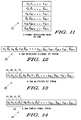
- FIGs. 9 through 14 illustrate one embodiment, based on block coding and block interleaving with six codewords per interleaving block, of the various signals generated within the system controller 22 of FIG. 2 utilizing 16 QAM modulation.
- quantities of codewords per interleaving block other than the illustrated example (six per interleaving block) are within the realm of the present invention.
- the described method of the present invention is easily extended further to higher orders of modulation such as 64 QAM and 256 QAM.
- 16 QAM four calls, A, B, C, and D, are received by the system controller 22.
- the four calls may be destined for up to four different wireless communication devices in any combination.
- the four calls are processed by the message processor 60 and sent to the channel manager 62.
- the channel manager 62 sends calls A and B to the first interleaver 64 and sends calls C and D to the second interleaver 66.
- the first interleaver 64 generates the I-channel interleaving block 72 as illustrated in FIG. 9 for the first set of calls 70 (A and B).
- the elements for Call A are identified by the letter "a" and the elements of Call B are identified by the letter "b".
- the first interleaver 64 then generates the interleaved I-channel bit stream 74 from the I-channel interleaving block 72; and sends the interleaved I-channel bit stream 74 to the multiplexer 68.
- FIG. 10 illustrates the interleaved I-channel bit stream 74 for this 16 QAM modulation example.
- the second interleaver 66 generates the Q-channel interleaving block 78 as illustrated in FIG. 11 for the second set of calls 76 (C and D). In FIG. 11, the letter "c" identifies the elements of Call C and the letter "d" identifies the elements of Call D.
- the second interleaver 66 then generates the interleaved Q-channel bit stream 80 from the Q-channel interleaving block 78; and sends the interleaved Q-channel bit stream 80 to the multiplexer 68.
- FIG. 12 illustrates the interleaved Q-channel bit stream 80 for this 16 QAM modulation example.
- the multiplexer 68 multiplexes the interleaved I-channel bit stream 74 and the interleaved Q-channel bit stream 80 to create the multiplexed bit stream 82.
- FIG. 13 illustrates the multiplexed bit stream 82.
- the multiplexed bit stream 82 is then communicated through the communication interface 46 by way of the communication links 24 to the radio frequency base transmitter 26. In the radio frequency base transmitter 26, the multiplexed bit stream 82 is converted into a complex symbol stream 83.
- FIG. 14 illustrates the complex symbol stream 83.
- the complex symbol stream 83 is comprised of a plurality of symbols. As illustrated in FIG. 14, a symbol 89 of the complex symbol stream 83 is comprised of the first bit 84, the second bit 86, a third bit 91, and a fourth bit 92.
- the complex symbol stream 83 is modulated onto the radio frequency carrier.
- the I-channel bits are used to modulate the in-phase component of the radio frequency carrier and the Q-channel bits are used to modulate the quadrature component of the radio frequency carrier.
- the modulated complex symbol stream is then sent to one or more wireless communication devices as the downlink call 34 (see FIG. 1 ).
- FIG. 15 summarizes the interaction of the various signals generated by the system controller 22 of FIG. 2 in accordance with the present invention.
- the first sets of calls 70 including the first call 85 are interleaved into the I-channel interleaving block 72.
- the second set of calls 76 including the second call 87 are interleaved into the Q-channel interleaving block 78.
- the data in the I-channel interleaving block 72 is output as the I-channel bit stream 74.
- the data in the Q-channel interleaving block 78 is output as the Q-channel bit stream 80.
- the I-channel bit stream 74 and the Q-channel bit stream 80 are then multiplexed together to form the multiplexed bit stream 82.
- the multiplexed bit stream 82 is converted into the complex symbol stream 83.
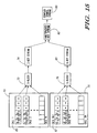
- FIG. 16 is an electrical block diagram of the wireless communication device 35 for use within the wireless communication system 10 of FIG. 1 in accordance with the present invention.
- the wireless communication device 35 includes a first antenna 88 for receiving the downlink call 34 sent from the wireless communication system 10.
- the first antenna 88 is coupled to a receiver 90 employing conventional demodulation techniques for receiving communications from the wireless communication system 10.
- FIG. 17 illustrates one embodiment of the downlink call 34; wherein the downlink call 34 comprises an address 95, a channel identifier 97, and a data block 99.
- the address 95 and the channel identifier 97 may alternatively be sent in a separate message prior to sending the data block 99 to the wireless communication device 35.
- a call manager 94 utilizing conventional signal processing techniques for processing the downlink call 34.
- the call manager 94 is similar to the MC68328 micro-controller manufactured by Motorola, Inc. of Schaumburg, Illinois. It will be appreciated that other similar processors can be utilized for the call manager 94, and that additional processors of the same or alternative type can be added as required to handle the processing requirements of the call manager 94.
- the call manager 94 decodes the address 95 of the downlink call 34, compares the decoded address with one or more addresses stored in an address memory 96, and when a match is detected, proceeds to process the remaining portion of the downlink call 34.
- the call manager 94 next determines which portion of the downlink call 34 (the I-channel or Q-channel) contains the call destined for the wireless communication device 35.
- the call manager 94 includes a channel parameter 101 that defines the channel of which the downlink call 34 is contained.
- the channel identifier 97 may be sent along with the data block 99 of the downlink call 34.
- One of ordinary skill in the art will recognize that other similar methods may be used to determine which channel contains the downlink call 34.
- Coupled to the call manager 94 are an I-channel processor 98 and a Q-channel processor 100.
- the I-channel processor 98 receives the downlink call 34 from the call manager 94 when the call destined for the wireless communication device is contained within the I-channel bit stream 74 portion of the downlink call 34.
- the Q-channel processor 100 receives the downlink call 34 from the call manager 94 when the call destined for the wireless communication device 35 is contained within the Q-channel bit stream 80 portion of the downlink call 34.
- the I-channel processor 98 and the Q-channel processor 100 are similar to the MC68328 micro-controller manufactured by Motorola, Inc. of Schaumburg, Illinois. It will be appreciated that other similar processors can be utilized for the I-channel processor 98 and the Q-channel processor 100, and that additional processors of the same or alternative type can be added as required to handle the processing requirements of each of the two processors.
- FIG. 18 is an electrical block diagram of an I-channel processor 98 for use within the wireless communication device 35 of FIG. 16.
- the I-channel processor 98 comprises a first demodulator 112 and an I-channel deinterleaver 114.
- the first demodulator 112 in one embodiment is a variable rate QAM demodulator for extracting the QAM modulation level from the complex symbol stream 83 of the downlink call 34; and demodulating the complex symbol stream 83 according to the QAM modulation level, thereby generating a first demodulated bit stream 113.
- Utilizing variable rate QAM demodulation facilitates scaling between different QAM modes.
- the QAM modulation level is specified prior to demodulation.
- the I-channel deinterleaver 114 deinterleaves the first demodulated bit stream 113, generating an I-channel bit stream 115.
- FIG. 19 is an electrical block diagram of a Q-channel processor 100 for use within the wireless communication device 35 of FIG. 16.
- the Q-channel processor 100 comprises a second demodulator 116 and a Q-channel deinterleaver 118.
- the second demodulator 116 in one embodiment is a variable rate QAM demodulator, extracting the QAM modulation level from the complex symbol stream 83 of the downlink call 34; and demodulating the complex symbol stream 83 according to the QAM modulation level, thereby generating a second demodulated bit stream 117.
- Utilizing variable rate QAM demodulation facilitates scaling between different QAM modes.
- the QAM modulation level is specified prior to demodulation.
- the Q-channel deinterleaver 118 deinterleaves the second demodulated bit stream 117, generating a Q-channel bit stream 119.
- the I-channel processor 98 and the Q-channel processor 100 are coupled to a controller 102 for processing the I-channel bit stream 115 received from the I-channel processor 98 or the Q-channel bit stream 119 received from the Q-channel processor 100.
- the controller 102 is similar to the MC68328 micro-controller manufactured by Motorola, Inc. of Schaumburg, Illinois. It will be appreciated that other similar processors can be utilized for the controller 102, and that additional processors of the same or alternative type can be added as required to handle the processing requirements of the controller 102.
- the controller 102 is coupled to a message memory 104 including a random access memory (RAM) and an electrically erasable programmable read-only memory (EEPROM).
- the controller 102 stores the I-channel bit stream 115 or the Q-channel bit stream 119 in the message memory 104.
- the controller 102 preferably also sends a command to a display 106, coupled to the controller 102, to generate a visual notification of the storage of the I-channel bit stream 115 or the Q-channel bit stream 119.
- a display 106 receives the command from the controller 102 that the I-channel bit stream 115 or the Q-channel bit stream 119 has been stored in the message memory 104, an indication is displayed.
- the indication for example may be the activation of one of a plurality of icons on the display 106.
- the controller 102 is further coupled to a user interface 120.
- the user interface 120 may provide a button press, a series of button presses, a voice response by the device user, or some other similar method of input by the device user. Selection via the user interface 120 of the indicator associated with the I-channel bit stream 115 or the Q-channel bit stream 119 displays the call on the display screen in the case of data messages.
- the display 106 may be, for example, a full or partial starburst liquid crystal display. It will be appreciated that other similar displays can be utilized for the display 106.
- the controller 102 in one embodiment is coupled to a speaker 108. Selection via the user interface 120 of the indicator associated with the I-channel bit stream 115 or the Q-channel bit stream 119 annunciates the call on the speaker 108 in the case of voice messages.
- the speaker 108 preferably is driven from circuitry capable of producing both melodies and voice recordings.
- the wireless communication device 35 of FIG. 16 includes an alert circuit 110 coupled to the controller 102.
- the controller 102 sends a command to the alert circuit 110 to generate an alert notification of the storage of the I-channel bit stream 115 or the Q-channel bit stream 119.
- the alert circuit 110 may utilize a transducer for the generation of an audible alert or a vibrator for the generation of a vibratory alert.
- a transducer for the generation of an audible alert or a vibrator for the generation of a vibratory alert.
- FIG. 20 is an electrical block diagram of an alternate embodiment of the wireless communication device 35 of FIG. 16 in accordance with the present invention.
- the reference numbers of the embodiment of FIG. 16 have been retained for those elements that are common.
- the wireless communication device 35 includes all the elements and functionality illustrated in FIG. 16 and previously described; and further comprises a QAM modulator 124, a transmitter 132, a second antenna 134, and a microphone 135.
- the controller 102 In response to the user interface 120, the controller 102 generates a reply command 122.
- the QAM modulator 124 is coupled to the controller 102 and is responsive to the commands of the controller 102. Upon receipt of the reply command 122 from the controller 102, the QAM modulator 124 modulates the reply command 122 to generate a QAM call 126.
- the transmitter 132 is coupled to the QAM modulator 124. When the transmitter 132 receives the QAM call 126 from the QAM modulator 124, the transmitter 132 generates the uplink call 44 and sends the uplink call 44 via the second antenna 134 to the wireless communication system 10.
- the wireless communication device 35 of FIG. 20 includes the microphone 135 coupled to the controller 102.
- the controller 102 In response to a signal from the microphone 135, the controller 102 generates the reply command 122, initiating string of circuitry to generate and send the uplink call 44 via the second antenna 134 to the wireless communication system 10 as described above.
- FIG. 21 is a flowchart illustrating the operation of the wireless communication device 35 of FIG. 16.
- the wireless communication device 35 receives the downlink call 34 including the complex symbol stream 83 from the wireless communication system 10.
- the call manager 94 determines if the desired call is contained within the I-channel bit stream 74 of the complex symbol stream 83.
- the I-channel processor 98 processes the I-channel portion of the downlink call 34.
- the call manager 94 checks if the desired call is contained within the Q-channel bit stream 80 of the complex symbol stream 83.
- Step 168 when the desired call is contained within the Q-channel bit stream 80, the Q-channel processor 100 processes the Q-channel portion of the downlink call 34.
- Step 170 when the downlink call 34 is not contained within the Q-channel bit stream 80, the processing of the downlink call 34 is aborted.
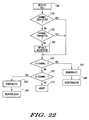
- FIG. 22 is a flowchart illustrating more detail of the operation of the wireless communication device 35.
- the wireless communication device 35 receives the downlink call 34 including the complex symbol stream 83 from the wireless communication system 10.
- the call manager 94 checks the complex symbol stream 83 for the presence of the channel identifier 97.
- the call manager 94 determines if it has been preprogrammed with the channel parameter 101.
- the call manager 94 implements a default algorithm.
- Step 182 when the channel identifier 97, the channel parameter 101 or the default algorithm is detected, the call manager 94 determines whether the desired call is contained within the I-channel bit stream 74 based on the data contained therein.
- Step 184 when the desired call is contained within the I-channel bit stream 74, the I-channel processor 98 demodulates the I-channel portion of the downlink call 34, generating the first demodulated bit stream 113.
- Step 188 the first demodulated bit stream 113 is deinterleaved, generating the I-channel bit stream 115.
- Step 190 when the desired call is not contained within the I-channel bit stream 74, the call manager 94 checks if the desired call is contained within the Q-channel bit stream 80 in Step 190.
- Step 170 when the desired call is not contained within the Q-channel bit stream 80, the processing is aborted.
- Step 192 when the desired call is contained within the Q-channel bit stream 80, the Q-channel processor 100 demodulates the Q-channel portion of the downlink call 34, generating the second demodulated bit stream 117.
- Step 196 the second demodulated bit stream 117 is deinterleaved, generating the Q-channel bit stream 119.
- FIG. 23 is a flowchart illustrating the further operation of the wireless communication device 35 of FIG. 20.
- the controller 102 checks for input from the user interface 120. When no user interface 120 is detected, the controller 102 continues periodical checking.
- the reply command 122 is sent from the controller 102 to the QAM modulator 124.
- the QAM modulator 124 modulates the reply command 122, generating the QAM call 126.
- the transmitter 132 transmits the uplink call 44 generated from the QAM call 126 via the second antenna 134.
- the method and apparatus for communicating a call herein described reduces the complexity of the implementation of variable rate QAM modulation between the base station transmitters and the wireless communication devices in a wireless communication system while preserving the burst error protection and overall improved call quality. This reduction in complexity reduces the processing requirement for the wireless communication device, thereby improving its battery life.
Abstract
Description
- This invention relates in general to wireless communication systems and in particular to the communication of calls within a wireless communication system.
- Wireless communication systems today employ a variety of modulation schemes from analog modulation to digital modulation such as binary phase modulation and binary frequency modulation. The type of modulation utilized greatly affects the performance, of the wireless communication system. Considerable effort is spent in the optimization of key performance elements such as bandwidth, demodulator performance and error control strategy for overall enhancement of data throughput.
- As the available spectrum for wireless communications becomes a premium due to the increasing number of subscribers, more bandwidth efficient transmission methods are required. Recently, designers have demonstrated that multilevel modulation schemes such as multilevel phase shift keying and quadrature amplitude modulation (QAM) provide efficient modulation techniques to meet the performance requirements of the wireless communication systems. Of these, QAM, a bandwidth efficient transmission method, yields the highest potential data throughput by its use of amplitude as well as phase modulation.
- QAM is the amplitude modulation and demodulation of two carriers that have the same frequency but are in phase quadrature to each other. It can be either analog or digital. QAM has been shown to be a suitable modulation scheme for wireless communication systems.
- Further, variable rate QAM modulation has been found to be an efficient modulation scheme capable of substantial performance gains over conventional QAM. In variable rate QAM modulation, the wireless communication device and the base station transmitter coordinate to determine an optimum modulation rate based on signal conditions and channel loading. The baud rate in such a system is fixed, but multiple modulation levels are allowed (2QAM, 4QAM, 16QAM etc.). QAM transmissions over wireless communication channels are subject to a variety of impairments, including interference, noise, multipath fading, and delay spread. In general, higher modulation levels (16 QAM, 64 QAM, etc.) are less tolerant to these impairments than lower modulation levels (2 QAM or 4 QAM). With variable rate QAM techniques, the modulation level is adapted to the existing channel conditions, usually using the highest modulation level which meets some minimum performance requirements (Bit error rate, packet loss, etc.)
- As a further enhancement to conventional variable QAM modulation, a pilot carrier can be transmitted along with the data to provide a reference for coherent demodulation. For a further description of this enhancement, please refer to U.S. Patent 4,816, 783 by Leitch, entitled "Method and Apparatus for Quadrature Modulation", and assigned to Motorola Inc. of Schaumburg, Illinois, the assignee of the present invention.
- WO-A-96/19055 describes an OFDM communication system where two OFDM channels are provided on the in phase and quadrature components of each subcarrier.
- The improved system capacity achieved must be balanced with the increased cost of the wireless communication system due to the increased complexity of variable rate QAM modulation techniques. What is needed is a method to reduce the complexity of the implementation of variable rate QAM modulation between the base station transmitters and the wireless communication devices in a wireless communication system.
- In accordance with an aspect of the present invention there is provided a method, a system controller and a wireless communication device according to the accompanying claims.
-
- FIG. 1 is an electrical block diagram of a wireless communication system;
- FIG. 2 is an electrical block diagram of a system controller for use within the wireless communication system of FIG. 1 in accordance with the present invention;
- FIGs. 3 through 8 illustrate one embodiment of the various signals generated within the system controller of FIG. 2 utilizing a 4 QAM system;
- FIGs. 9 through 14 illustrate one embodiment of the various signals generated within the system controller of FIG. 2 utilizing a 16 QAM system;
- FIG. 15 illustrates the interaction of the various signals generated by the system controller of FIG. 2 in accordance with the present invention;
- FIG. 16 is an electrical block diagram of a wireless communication device for use within the wireless communication system of FIG. 1 in accordance with the present invention;
- FIG. 17 illustrates a signal for communication within the wireless communication system of FIG. 1;
- FIG. 18 is an electrical block diagram of an I-channel processor for use within the wireless communication device of FIG. 12;
- FIG. 19 is an electrical block diagram of a Q-channel processor for use within the wireless communication device of FIG. 12;
- FIG. 20 is an electrical block diagram of an alternate embodiment of the wireless communication device of FIG. 12;
- FIG. 21 is a flowchart illustrating the operation of the wireless communication device of FIG. 16;
- FIG. 22 is a flowchart illustrating more detail of one embodiment of the operation as illustrated in FIG. 21; and
- FIG. 23 is a flowchart illustrating the operation of the wireless communication device of FIG. 20.
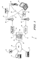
- Referring to FIG. 1, a block diagram of a
wireless communication system 10 is shown. Thewireless communication system 10 comprises a message input device, such as atelephone 12, acomputer 14, or adesktop messaging unit 16, connected through a conventional public switched telephone network (PSTN) 18 through a plurality ofconventional telephone links 20 to asystem controller 22. Thetelephone links 20 may be a plurality of twisted wire pairs, or a multiplexed trunk line. - The
system controller 22 is coupled to and oversees the operation of at least one radiofrequency base transmitter 26 and, preferably, at least one radiofrequency base receiver 28 through one ormore communication links 24. Thecommunication links 24 typically are twisted pair telephone wires, and additionally can include radio frequency (RF), microwave, or high quality audio communication links. The radiofrequency base transmitter 26 and the radiofrequency base receiver 28, which typically are message store and forward stations that encode and decode inbound and outbound telephone addresses into formats that are compatible with landline message switch computers and personal radio telephone addressing requirements, such as cellular message protocols. Thesystem controller 22 can also function to encode and decode wireless messages that are transmitted to or received by the radiofrequency base transmitter 26 or the radiofrequency base receiver 28. Telephony signals are typically transmitted to and received from thesystem controller 22 by telephone sets such as thetelephone 12 or thewireless communication device 35. Thesystem controller 22 encodes and schedules outbound messages such as adownlink call 34, for transmission by the radiofrequency base transmitter 26 via atransmit antenna 30 to at least onewireless communication device 35 on at least one outbound radio frequency (RF)channel 32. As illustrated in FIG. 1, thewireless communication device 35 may be, for example, a cellular telephone or a pager. Thedownlink call 34 may be, for example, a data message, a voice message, or a telephone call. Similarly, thesystem controller 22 receives and decodes inbound messages such as anuplink call 44 received by the radiofrequency base receiver 28 via areceive antenna 40 on at least oneinbound RF channel 42 from thewireless communication device 35. Theuplink call 44 may be, for example, a data message, a reply to a data message, a telephone call, or a reply to a telephone call. - It will be appreciated that the
wireless communication system 10, in accordance with the present invention, may function utilizing any wireless RF channel, for example, a one or two way pager channel, a mobile cellular channel, or a mobile radio channel. Similarly, it will be appreciated that thewireless communication system 10 may function utilizing other types of channels such as infrared channels. In the following description, the term wireless communication system refers to any of the wireless communication systems mentioned above or an equivalent. - Similarly, it will be appreciated that the
wireless communication device 35, in accordance with the present invention, may be a mobile cellular telephone, a mobile radio data terminal, a mobile cellular telephone having an attached data terminal, or a one or two way pager. In the following description, the term "wireless communication device" refers to any of the devices mentioned above or an equivalent. - Each
wireless communication device 35 assigned for use in thewireless communication system 10 has an address assigned thereto which is a unique selective call address in thewireless communication system 10. The address enables the transmission of thedownlink call 34 from thesystem controller 22 only to thewireless communication device 35 having that address, and identifies the messages and responses received at thesystem controller 22 from thewireless communication device 35. Furthermore, eachwireless communication device 35 also has a pin number assigned thereto, the pin number being associated with a telephone number within thePSTN 18. A list of the assigned addresses and correlated telephone numbers for eachwireless communication device 35 is stored in thesystem controller 22 in the form of asubscriber database 56. - FIG. 2 is an electrical block diagram of the
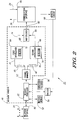
system controller 22 for use in thewireless communication system 10 of FIG. 1 in accordance with the preferred embodiment of the present invention. Thesystem controller 22 comprises acommunication interface 46, amessage handler 48, atelephone interface 50, amessage memory 52, anencoder 54, thesubscriber database 56, and anaddress circuit 58. - The
communication interface 46 queues data and stored voice messages for transmission to thewireless communication device 35, and receives acknowledgements, data responses, data messages, and telephone calls from thewireless communication device 35. Thecommunication interface 46 is coupled to the radiofrequency base transmitter 26 and the radiofrequency base receiver 28 of FIG. 1 by the communication links 24. - The
message handler 48, which routes and processes the messages, is coupled to thecommunication interface 46, and is further coupled to thetelephone interface 50,message memory 52, theencoder 54, and thesubscriber database 56. Thetelephone interface 50 handles the PSTN 18 (see FIG. 1) physical connection, connecting and disconnecting telephone calls at the telephone links 20, and routing the audio signals between the telephone links 20 and themessage handler 48. Thesubscriber database 56 stores information for each subscriber. This subscriber information may include a correlation between the assigned address and the telephone number used within thePSTN 18 to route messages and telephone calls to eachwireless communication device 35. It may also include other subscriber-defined preferences, such as hours during which messages are to be held back from delivery to thewireless communication device 35; and hours where the messages for thewireless communication device 35 are forwarded to a different device. Themessage memory 52 stores calls and replies in queue for scheduled delivery to thewireless communication device 35. Theencoder 54 is coupled to themessage handler 48 and theaddress circuit 58, and encodes messages intended for transmission to thewireless communication device 35. - Preferably, the
message handler 48 comprises amessage processor 60, achannel manager 62, afirst interleaver 64, asecond interleaver 66, and amultiplexer 68. Themessage processor 60 is coupled to and interfaces with thetelephone interface 50, themessage memory 52, theencoder 54 and thesubscriber database 56 to process the calls and the messages. The call processing performed by themessage processor 60 includes source encoding (such as digitizing voice messages) and error correction encoding. Thechannel manager 62 is coupled between themessage processor 60 and the first and second interleavers (64, 66). Thechannel manager 62 assigns the calls received from themessage processor 60 to either thefirst interleaver 64 or thesecond interleaver 66 in a pre-determined manner. Preferably, thechannel manager 62 assigns the calls based on a preprogrammed algorithm. Alternatively, the calls received may include an instruction of channel assignment. One of ordinary skill in the art will recognize that other equivalent methods of channel assignment are within the scope of the present invention. - The
first interleaver 64 interleaves a first set ofcalls 70 including afirst call 85 received from thechannel manager 62 into an I-channel interleaving block 72. The data in the I-channel interleaving block 72 is then output as an I-channel bit stream 74. Thesecond interleaver 66 interleaves a second set ofcalls 76 including asecond call 87 received from thechannel manager 62 into a Q-channel interleaving block 78. The data in the Q-channel interleaving block 78 is then output as a Q-channel bit stream 80. Themultiplexer 68 is coupled to thefirst interleaver 64 and thesecond interleaver 66 and multiplexes the I-channel bit stream 74 received from thefirst interleaver 64 and the Q-channel bit stream 80 received from thesecond interleaver 66 into a multiplexedbit stream 82, to be described below. The output of themultiplexer 68 is coupled to thecommunication interface 46. Upon receipt of the multiplexedbit stream 82 from themultiplexer 68, thecommunication interface 46 forwards the multiplexedbit stream 82 to the radio frequency base transmitter 26 (see FIG. 1) through the communication links 24. The radiofrequency base transmitter 26 generates thedownlink call 34 from the multiplexedbit stream 82 for transmission to thewireless communication device 35 over theoutbound RF channel 32 via the transmitantenna 30. - The
system controller 22 is preferably a EMX5000 switching terminal manufactured by Motorola Inc, of Schaumburg, Illinois, modified with firmware elements in accordance with the preferred embodiment of the present invention, as described herein. Thecommunication interface 46, themessage handler 48, themessage memory 52, thesubscriber database 56, theencoder 54, theaddress circuit 58, and thetelephone interface 50 are preferably implemented within portions of the EMX5000 switching terminal. These portions include, but are not limited to, those portions providing program memory, a central processing unit, input/output peripherals, and a random access memory. Thesystem controller 22 alternatively could be implemented using a RF-Conductor! Model 3000 series network controller manufactured by Motorola Inc. of Schaumburg, Illinois. Thesubscriber database 56 and themessage memory 52 may alternatively be implemented as magnetic or optical disc memory, which may alternatively be external to thesystem controller 22. It will be appreciated by one of ordinary skill in the art that other similar terminals can be utilized for thesystem controller 22, and that additional infrastructure equipment of the same or alternative type can be added as required to handle the requirements of thesystem controller 22. - It should be noted that the
system controller 22 is capable of operating in a distributed transmission control environment that allows the mixing of cellular, simulcast, master/slave, or other coverage schemes. Such an environment may include a plurality of radio frequency transmitters, radio frequency receivers, transmit antennas and receive antennas for providing reliable radio signals within a geographic area as large as a nationwide network. Moreover, one of ordinary skill in the art would recognize that the telephony and wireless communication system functions may reside in separate system controllers which operate either independently or in a networked fashion. - FIGs. 3 through 8 illustrate one embodiment, based on linear block coding and block interleaving with three codewords per interleaving block, of the various signals generated within the system controller of FIG. 2 utilizing 4 QAM modulation. One of ordinary skill in the art would recognize that quantities of codewords per interleaving block other than the illustrated example (three per interleaving block) are within the realm of the present invention. Referring to FIG. 2 for explanatory purposes, the
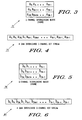
system controller 22 receives two calls A and B. Call A is destined for a first wireless communication device and call B is destined for a second wireless communication device. The two calls are processed by themessage processor 60 and then sent to thechannel manager 62. Thechannel manager 62 sends call A to thefirst interleaver 64 and call B to thesecond interleaver 66. Thefirst interleaver 64 then generates an I-channel interleaving block 72. FIG. 3 illustrates the I-channel interleaving block 72 generated by thefirst interleaver 64 for the first call A, whose elements are identified by the letter "a". Thefirst interleaver 64 then generates the interleaved I-channel bit stream 74 from the I-channel interleaving block 72; and sends the interleaved I-channel bit stream 74 to themultiplexer 68. FIG. 4 illustrates the interleaved I-channel bit stream 74. Thesecond interleaver 66 generates a Q-channel interleaving block 78. FIG. 5 illustrates the Q-channel interleaving block 78 generated by thesecond interleaver 66 for the second call B, whose elements are identified by the letter "b". Thesecond interleaver 66 then generates the interleaved Q-channel bit stream 80 from the Q-channel interleaving block 78; and sends the interleaved Q-channel bit stream 80 to themultiplexer 68. FIG. 6 illustrates the interleaved Q-channel bit stream 80 that is sent utilizing the Q-channel interleaving block 78. Themultiplexer 68 multiplexes the interleaved I-channel bit stream 74 and the interleaved Q-channel bit stream 80 to create the multiplexedbit stream 82. FIG. 7 illustrates the multiplexedbit stream 82. The multiplexedbit stream 82 is then communicated through thecommunication interface 46 by way of the communication links 24 to the radiofrequency base transmitter 26. In the radiofrequency base transmitter 26, the multiplexedbit stream 82 is converted into acomplex symbol stream 83. - FIG. 8 illustrates the
complex symbol stream 83. Thecomplex symbol stream 83 is comprised of a plurality of symbols. As illustrated in FIG. 8, asymbol 89 of thecomplex symbol stream 83 is comprised of afirst bit 84 from thefirst call 85 of the I-channel bit stream 74 paired with asecond bit 86 from thesecond call 87 of the Q-channel bit stream 80. Thecomplex symbol stream 83 is modulated onto the radio frequency carrier. The I-channel bits are used to modulate the in-phase component of the radio frequency carrier and the Q-channel bits are used to modulate the quadrature component of the radio frequency carrier. The modulated complex symbol stream is then sent to one or more wireless communication devices as the downlink call 34 (see FIG.1). - Separately interleaving the two calls for the I-channel and Q-channel accomplishes several things. First, the first wireless communication device listening to the first call 85 (call A) is required only to demodulate the I-channel portion of each received
downlink call 34; and the second wireless communication device listening to the second call (call B) is required only to demodulate the Q-channel portion of the receiveddownlink call 34. - In summary, separately interleaving calls, as described herein for the present invention, results in a simple algorithm and reduced processing in each wireless communication device. Separately interleaving reduces the requirement for the wireless communication device to fully demodulate both the I-channel and the Q-channel of a QAM channel. Lowering the demodulator overhead thereby improves battery life of the wireless communication device. Further, the burst error protection is improved over traditional methods by evenly distributing the errors across the two calls. This improvement increases the likelihood of error correction in the wireless communication device and therefore improves overall call quality.
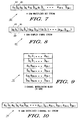
- The preferred interleaving method of the present invention can be extended to higher order QAM cases as well. FIGs. 9 through 14 illustrate one embodiment, based on block coding and block interleaving with six codewords per interleaving block, of the various signals generated within the
system controller 22 of FIG. 2 utilizing 16 QAM modulation. One of ordinary skill in the art would recognize that quantities of codewords per interleaving block other than the illustrated example (six per interleaving block) are within the realm of the present invention. Further, one of ordinary skill in the art will recognize that the described method of the present invention is easily extended further to higher orders of modulation such as 64 QAM and 256 QAM. In the example of 16 QAM, four calls, A, B, C, and D, are received by thesystem controller 22. The four calls may be destined for up to four different wireless communication devices in any combination. The four calls are processed by themessage processor 60 and sent to thechannel manager 62. Thechannel manager 62 sends calls A and B to thefirst interleaver 64 and sends calls C and D to thesecond interleaver 66. Thefirst interleaver 64 generates the I-channel interleaving block 72 as illustrated in FIG. 9 for the first set of calls 70 (A and B). In FIG. 9, the elements for Call A are identified by the letter "a" and the elements of Call B are identified by the letter "b". Thefirst interleaver 64 then generates the interleaved I-channel bit stream 74 from the I-channel interleaving block 72; and sends the interleaved I-channel bit stream 74 to themultiplexer 68. FIG. 10 illustrates the interleaved I-channel bit stream 74 for this 16 QAM modulation example. Thesecond interleaver 66 generates the Q-channel interleaving block 78 as illustrated in FIG. 11 for the second set of calls 76 (C and D). In FIG. 11, the letter "c" identifies the elements of Call C and the letter "d" identifies the elements of Call D. Thesecond interleaver 66 then generates the interleaved Q-channel bit stream 80 from the Q-channel interleaving block 78; and sends the interleaved Q-channel bit stream 80 to themultiplexer 68. FIG. 12 illustrates the interleaved Q-channel bit stream 80 for this 16 QAM modulation example. Themultiplexer 68 multiplexes the interleaved I-channel bit stream 74 and the interleaved Q-channel bit stream 80 to create the multiplexedbit stream 82. FIG. 13 illustrates the multiplexedbit stream 82. The multiplexedbit stream 82 is then communicated through thecommunication interface 46 by way of the communication links 24 to the radiofrequency base transmitter 26. In the radiofrequency base transmitter 26, the multiplexedbit stream 82 is converted into acomplex symbol stream 83. - FIG. 14 illustrates the
complex symbol stream 83. Thecomplex symbol stream 83 is comprised of a plurality of symbols. As illustrated in FIG. 14, asymbol 89 of thecomplex symbol stream 83 is comprised of thefirst bit 84, thesecond bit 86, athird bit 91, and afourth bit 92. Thecomplex symbol stream 83 is modulated onto the radio frequency carrier. The I-channel bits are used to modulate the in-phase component of the radio frequency carrier and the Q-channel bits are used to modulate the quadrature component of the radio frequency carrier. The modulated complex symbol stream is then sent to one or more wireless communication devices as the downlink call 34 (see FIG.1). - FIG. 15 summarizes the interaction of the various signals generated by the
system controller 22 of FIG. 2 in accordance with the present invention. The first sets ofcalls 70 including thefirst call 85 are interleaved into the I-channel interleaving block 72. The second set ofcalls 76 including thesecond call 87 are interleaved into the Q-channel interleaving block 78.The data in the I-channel interleaving block 72 is output as the I-channel bit stream 74. The data in the Q-channel interleaving block 78 is output as the Q-channel bit stream 80. The I-channel bit stream 74 and the Q-channel bit stream 80 are then multiplexed together to form the multiplexedbit stream 82. The multiplexedbit stream 82 is converted into thecomplex symbol stream 83. - FIG. 16 is an electrical block diagram of the
wireless communication device 35 for use within thewireless communication system 10 of FIG. 1 in accordance with the present invention. Thewireless communication device 35 includes afirst antenna 88 for receiving thedownlink call 34 sent from thewireless communication system 10. Thefirst antenna 88 is coupled to areceiver 90 employing conventional demodulation techniques for receiving communications from thewireless communication system 10. FIG. 17 illustrates one embodiment of thedownlink call 34; wherein thedownlink call 34 comprises anaddress 95, achannel identifier 97, and adata block 99. Those skilled in the art will recognize that theaddress 95 and thechannel identifier 97 may alternatively be sent in a separate message prior to sending the data block 99 to thewireless communication device 35. - Referring back to FIG. 16, coupled to the
receiver 90 is acall manager 94 utilizing conventional signal processing techniques for processing thedownlink call 34. Preferably, thecall manager 94 is similar to the MC68328 micro-controller manufactured by Motorola, Inc. of Schaumburg, Illinois. It will be appreciated that other similar processors can be utilized for thecall manager 94, and that additional processors of the same or alternative type can be added as required to handle the processing requirements of thecall manager 94. Thecall manager 94 decodes theaddress 95 of thedownlink call 34, compares the decoded address with one or more addresses stored in anaddress memory 96, and when a match is detected, proceeds to process the remaining portion of thedownlink call 34. Thecall manager 94 next determines which portion of the downlink call 34 (the I-channel or Q-channel) contains the call destined for thewireless communication device 35. Preferably, thecall manager 94 includes achannel parameter 101 that defines the channel of which thedownlink call 34 is contained. Alternatively, thechannel identifier 97 may be sent along with the data block 99 of thedownlink call 34. One of ordinary skill in the art will recognize that other similar methods may be used to determine which channel contains thedownlink call 34. - Coupled to the
call manager 94 are an I-channel processor 98 and a Q-channel processor 100. The I-channel processor 98 receives thedownlink call 34 from thecall manager 94 when the call destined for the wireless communication device is contained within the I-channel bit stream 74 portion of thedownlink call 34. The Q-channel processor 100 receives thedownlink call 34 from thecall manager 94 when the call destined for thewireless communication device 35 is contained within the Q-channel bit stream 80 portion of thedownlink call 34. Preferably, the I-channel processor 98 and the Q-channel processor 100 are similar to the MC68328 micro-controller manufactured by Motorola, Inc. of Schaumburg, Illinois. It will be appreciated that other similar processors can be utilized for the I-channel processor 98 and the Q-channel processor 100, and that additional processors of the same or alternative type can be added as required to handle the processing requirements of each of the two processors. - FIG. 18 is an electrical block diagram of an I-
channel processor 98 for use within thewireless communication device 35 of FIG. 16. Preferably, the I-channel processor 98 comprises afirst demodulator 112 and an I-channel deinterleaver 114. Thefirst demodulator 112 in one embodiment is a variable rate QAM demodulator for extracting the QAM modulation level from thecomplex symbol stream 83 of thedownlink call 34; and demodulating thecomplex symbol stream 83 according to the QAM modulation level, thereby generating a firstdemodulated bit stream 113. Utilizing variable rate QAM demodulation facilitates scaling between different QAM modes. In another embodiment, the QAM modulation level is specified prior to demodulation. The I-channel deinterleaver 114 deinterleaves the firstdemodulated bit stream 113, generating an I-channel bit stream 115. - FIG. 19 is an electrical block diagram of a Q-
channel processor 100 for use within thewireless communication device 35 of FIG. 16. Preferably, the Q-channel processor 100 comprises asecond demodulator 116 and a Q-channel deinterleaver 118. Thesecond demodulator 116 in one embodiment is a variable rate QAM demodulator, extracting the QAM modulation level from thecomplex symbol stream 83 of thedownlink call 34; and demodulating thecomplex symbol stream 83 according to the QAM modulation level, thereby generating a seconddemodulated bit stream 117. Utilizing variable rate QAM demodulation facilitates scaling between different QAM modes. In another embodiment, the QAM modulation level is specified prior to demodulation. The Q-channel deinterleaver 118 deinterleaves the seconddemodulated bit stream 117, generating a Q-channel bit stream 119. - Referring back to FIG. 16, the I-
channel processor 98 and the Q-channel processor 100 are coupled to acontroller 102 for processing the I-channel bit stream 115 received from the I-channel processor 98 or the Q-channel bit stream 119 received from the Q-channel processor 100. Preferably, thecontroller 102 is similar to the MC68328 micro-controller manufactured by Motorola, Inc. of Schaumburg, Illinois. It will be appreciated that other similar processors can be utilized for thecontroller 102, and that additional processors of the same or alternative type can be added as required to handle the processing requirements of thecontroller 102. - To perform the necessary functions of the
wireless communication device 35, thecontroller 102 is coupled to amessage memory 104 including a random access memory (RAM) and an electrically erasable programmable read-only memory (EEPROM). Thecontroller 102 stores the I-channel bit stream 115 or the Q-channel bit stream 119 in themessage memory 104. - The
controller 102 preferably also sends a command to adisplay 106, coupled to thecontroller 102, to generate a visual notification of the storage of the I-channel bit stream 115 or the Q-channel bit stream 119. When thedisplay 106 receives the command from thecontroller 102 that the I-channel bit stream 115 or the Q-channel bit stream 119 has been stored in themessage memory 104, an indication is displayed. The indication, for example may be the activation of one of a plurality of icons on thedisplay 106. - The
controller 102 is further coupled to auser interface 120. Theuser interface 120 may provide a button press, a series of button presses, a voice response by the device user, or some other similar method of input by the device user. Selection via theuser interface 120 of the indicator associated with the I-channel bit stream 115 or the Q-channel bit stream 119 displays the call on the display screen in the case of data messages. Thedisplay 106 may be, for example, a full or partial starburst liquid crystal display. It will be appreciated that other similar displays can be utilized for thedisplay 106. - The
controller 102 in one embodiment is coupled to aspeaker 108. Selection via theuser interface 120 of the indicator associated with the I-channel bit stream 115 or the Q-channel bit stream 119 annunciates the call on thespeaker 108 in the case of voice messages. Thespeaker 108 preferably is driven from circuitry capable of producing both melodies and voice recordings. - In one embodiment, the
wireless communication device 35 of FIG. 16 includes analert circuit 110 coupled to thecontroller 102. Thecontroller 102 sends a command to thealert circuit 110 to generate an alert notification of the storage of the I-channel bit stream 115 or the Q-channel bit stream 119. Thealert circuit 110 may utilize a transducer for the generation of an audible alert or a vibrator for the generation of a vibratory alert. One of ordinary skill in the art will appreciate that other alternative alert mechanisms are within the scope of the present invention. - FIG. 20 is an electrical block diagram of an alternate embodiment of the
wireless communication device 35 of FIG. 16 in accordance with the present invention. The reference numbers of the embodiment of FIG. 16 have been retained for those elements that are common. Thewireless communication device 35 includes all the elements and functionality illustrated in FIG. 16 and previously described; and further comprises aQAM modulator 124, atransmitter 132, asecond antenna 134, and amicrophone 135. - In response to the
user interface 120, thecontroller 102 generates areply command 122. The QAM modulator 124 is coupled to thecontroller 102 and is responsive to the commands of thecontroller 102. Upon receipt of thereply command 122 from thecontroller 102, theQAM modulator 124 modulates thereply command 122 to generate aQAM call 126. Thetransmitter 132 is coupled to theQAM modulator 124. When thetransmitter 132 receives the QAM call 126 from theQAM modulator 124, thetransmitter 132 generates theuplink call 44 and sends theuplink call 44 via thesecond antenna 134 to thewireless communication system 10. - In one embodiment, the
wireless communication device 35 of FIG. 20 includes themicrophone 135 coupled to thecontroller 102. In response to a signal from themicrophone 135, thecontroller 102 generates thereply command 122, initiating string of circuitry to generate and send theuplink call 44 via thesecond antenna 134 to thewireless communication system 10 as described above. - FIG. 21 is a flowchart illustrating the operation of the
wireless communication device 35 of FIG. 16. InStep 158, thewireless communication device 35 receives thedownlink call 34 including thecomplex symbol stream 83 from thewireless communication system 10. InStep 162, thecall manager 94 determines if the desired call is contained within the I-channel bit stream 74 of thecomplex symbol stream 83. When the desired call is contained within the I-channel bit stream 74, inStep 164 the I-channel processor 98 processes the I-channel portion of thedownlink call 34. InStep 166, when the desired call is not contained within the I-channel bit stream 74, thecall manager 94 checks if the desired call is contained within the Q-channel bit stream 80 of thecomplex symbol stream 83. InStep 168, when the desired call is contained within the Q-channel bit stream 80, the Q-channel processor 100 processes the Q-channel portion of thedownlink call 34. InStep 170, when thedownlink call 34 is not contained within the Q-channel bit stream 80, the processing of thedownlink call 34 is aborted. - FIG. 22 is a flowchart illustrating more detail of the operation of the
wireless communication device 35. InStep 158, thewireless communication device 35 receives thedownlink call 34 including thecomplex symbol stream 83 from thewireless communication system 10. InStep 176, thecall manager 94 checks thecomplex symbol stream 83 for the presence of thechannel identifier 97. InStep 178, when nochannel identifier 97 is detected in thecomplex symbol stream 83, thecall manager 94 determines if it has been preprogrammed with thechannel parameter 101. InStep 180, when nochannel parameter 101 is detected, thecall manager 94 implements a default algorithm. InStep 182, when thechannel identifier 97, thechannel parameter 101 or the default algorithm is detected, thecall manager 94 determines whether the desired call is contained within the I-channel bit stream 74 based on the data contained therein. InStep 184, when the desired call is contained within the I-channel bit stream 74, the I-channel processor 98 demodulates the I-channel portion of thedownlink call 34, generating the firstdemodulated bit stream 113. Next, inStep 188, the firstdemodulated bit stream 113 is deinterleaved, generating the I-channel bit stream 115. Referring back toStep 182, when the desired call is not contained within the I-channel bit stream 74, thecall manager 94 checks if the desired call is contained within the Q-channel bit stream 80 inStep 190. InStep 170, when the desired call is not contained within the Q-channel bit stream 80, the processing is aborted. InStep 192, when the desired call is contained within the Q-channel bit stream 80, the Q-channel processor 100 demodulates the Q-channel portion of thedownlink call 34, generating the seconddemodulated bit stream 117. Next, inStep 196, the seconddemodulated bit stream 117 is deinterleaved, generating the Q-channel bit stream 119. - FIG. 23 is a flowchart illustrating the further operation of the
wireless communication device 35 of FIG. 20. InStep 200, thecontroller 102 checks for input from theuser interface 120. When nouser interface 120 is detected, thecontroller 102 continues periodical checking. InStep 202, when theuser interface 120 is detected, thereply command 122 is sent from thecontroller 102 to theQAM modulator 124. InStep 204, theQAM modulator 124 modulates thereply command 122, generating theQAM call 126. Lastly, inStep 208, thetransmitter 132 transmits theuplink call 44 generated from the QAM call 126 via thesecond antenna 134. - The method and apparatus for communicating a call herein described reduces the complexity of the implementation of variable rate QAM modulation between the base station transmitters and the wireless communication devices in a wireless communication system while preserving the burst error protection and overall improved call quality. This reduction in complexity reduces the processing requirement for the wireless communication device, thereby improving its battery life.
Claims (26)
- A method for communicating a downlink call (34) in a wireless communication system (10) having a system controller (22), a radio frequency base transmitter (26), and at least one wireless communication device (35), the method comprising:interleaving a first set of calls (70), and generating an I-channel bit stream (74) comprised of the interleaved first set of calls;interleaving a second set of calls (76), and generating a Q-channel bit stream (80) comprised of the interleaved second set of calls;generating the downlink call (34) by modulating the I-channel bit stream (74) onto an in-phase carrier component of the downlink call (34) and modulating the Q-channel bit stream (80) onto a quadrature phase carrier component of the downlink call (34) characterized in that the first set of calls is for a first wireless communication device and the second set of calls is for a second wireless communication device.
- A method for communicating a downlink call (34) as recited in Claim 1 wherein the generating of the downlink call (34) further comprises:converting the multiplexed I-channel bit stream (74) and Q-channel bit stream (80) into a complex symbol stream (83).
- A method for communicating a downlink call (34) as recited in Claim 2, wherein the I-channel bit stream (74) includes a first bit from a first call and the Q-channel bit stream (80) includes a second bit from a second call, and further wherein the converting step comprises generating a symbol by pairing the first bit and the second bit.
- A method for communicating a downlink call (34) as recited in Claim 1 wherein the interleaving of the first set of calls (70) comprises:interleaving the first set of calls (70) into an I-channel interleaving block (72); andgenerating the I-channel bit stream (74) from the I-channel interleaving block (72).
- A method for communicating a downlink call (34) as recited in Claim 1 wherein the interleaving of the first set of calls (70) comprises:interleaving the second set of calls (76) into a Q-channel interleaving block (78); andgenerating the Q-channel bit stream (80) from the Q-channel interleaving block (78).
- A method for communicating a downlink call (34) as recited in Claim 1 further comprising:transmitting the downlink call (34) from the radio frequency base transmitter (26) to the wireless communication device; andprocessing the downlink call (34) within the wireless communication device (35).
- A method for communicating a downlink call (34) as recited in Claim 6 whereby the processing step comprises:receiving the downlink call (34); andprocessing the I-channel bit stream (74) to retrieve the first set of calls (70).
- A method for communicating a downlink call (34) as recited in Claim 6 whereby the processing step comprises:receiving the downlink call (34); andprocessing the Q-channel bit stream (80) to retrieve the second set of calls (76).
- A system controller (22) for controlling the communication of a downlink call (34) in a wireless communication system (10) employing quadrature amplitude modulation for communicating the downlink call (34) between a radio frequency base transmitter (26) and at least one wireless communication device (35), the system controller (22) comprising:a first interleaver (64), having an input and an output, for interleaving a first set of calls (70) and generating an I-channel bit stream (74) comprised of the interleaved first set of calls;a second interleaver (66), having an input and an output, for interleaving a second set of calls (76) and generating a Q-channel bit stream (80) comprised of the interleaved second set of calls; anda multiplexer (68) coupled to the output of the first interleaver (64) and the output of the second interleaver (66) for modulating the I-channel bit stream (74) onto an in-phase carrier component of the downlink call (34) and modulating the Q-channel bit stream (80) onto a quadrature phase carrier component of the downlink call (34) to generate the downlink call (34), characterized in that the first set of calls is for a first wireless communication device and thesecond set of calls is for a second wireless communication device.
- A system controller (22) as recited in Claim 9 further comprising:a channel manager (62) coupled to the input of the first interleaver (64) and the input of the second interleaver (66) for assigning a first set of calls (70) to the first interleaver (64) and a second set of calls (76) to the second interleaver (66).
- A system controller (22) as recited in claim 9, further comprising:a message processor (60) for processing a plurality of calls;a channel manager (62) coupled to the message processor (60), the first interleaver (64), and the second interleaver (66), for assigning the first set of calls (70) to the first interleaver (64) and the second set of calls (76) to the second interleaver (66); anda communication interface coupled to the multiplexer (68) for receiving the multiplexed signal and generating the downlink call (34).
- A wireless communication device (35) for receiving a downlink call (34) from a radio frequency base transmitter (26) in a wireless communication system (10) employing quadrature amplitude modulation, the wireless communication device (35) comprising:a receiver (90) for receiving the downlink call (34) including an I-channel bit stream (74) modulated onto an in-phase carrier component of the downlink call (34) and a Q-channel bit stream (80) modulated onto a quadrature phase carrier component of the downlink call (34), characterized by
the I-channel bit stream (74) comprising an interleaved first set of calls for a first wireless communication device, and
the Q-channel bit stream (80) comprising an interleaved second set of calls for a second wireless communication device;a call manager (94) coupled to the receiver (90) for routing the downlink call (34) to an I-channel processor (98) when the first set of calls (70) includes a call destined for the wireless communication device (35); andthe I-channel processor (98) coupled to the call manager (94) for processing the I-channel bit stream of the downlink call (34) received from the call manager (94). - A wireless communication device (35) as recited in Claim 12 wherein the I-channel processor (98) comprises:a demodulator (112) for demodulating the I-channel bit stream, and generating a first demodulated bit stream; andan I-channel deinterleaver (114) coupled to the demodulator (112), for receiving and deinterleaving the first demodulated bit stream.
- A wireless communication device (35) as recited in Claim 13, wherein the demodulator (112) comprises a variable rate QAM demodulator for extracting a QAM modulation level from the I-channel bit stream (74) and demodulating the I-channel bit stream (74) according to the extracted QAM modulation level.
- A wireless communication device (35) as recited in Claim 12 further comprising:a Q-channel processor (100) coupled to the (94) for processing the Q-channel bit stream (80) of the downlink call (34) received from the call manager (94), wherein the call manager (94) routes the downlink call (34) to the Q-channel processor (100) when the second set of calls (76) includes a call destined for the wireless communication device (35).
- A wireless communication device (35) as recited in Claim 15 wherein the Q-channel processor (100) comprises:a demodulator (116) for demodulating the Q-channel bit stream, and generating a second demodulated bit stream; anda Q-channel deinterleaver (118) coupled to the demodulator (116), for receiving and deinterleaving the second demodulated bit stream.
- A wireless communication device (35) as recited in Claim 16, wherein the demodulator (116) comprises a variable rate QAM demodulator for extracting a QAM modulation level from the Q-channel bit stream (80) and demodulating the Q-channel bit stream (80) according to the extracted QAM modulation level.
- A wireless communication device (35) as recited in Claim 12 further comprising:a QAM modulator for generating a QAM call; anda device transmitter (132) coupled to the QAM modulator for transmitting the uplink call (44).
- A method for receiving a call in a wireless communication device (35) from a wireless communication system (10) employing QAM modulation techniques, the method comprising:receiving a downlink call (34) including an I-channel bit stream (74) modulated onto an in-phase carrier component of the downlink call (34) and a Q-channel bit stream (80) modulated onto a quadrature phase carrier component of the downlink call (34) ; characterized byprocessing the I-channel bit stream (74) of the downlink call (34) to retrieve a first set of calls (70) when the first set of calls (70) includes a call destined for a first wireless communication device (35) processing the Q-channel bit stream (80) of the downlink call (34) to retrieve a second set of calls (76) when the second set of calls (76) includes a call destined for a second wireless communication device (35).
- A method as recited in Claim 19 wherein the processing step comprises:demodulating the I-channel bit stream (74), and generating a first demodulated bit stream; anddeinterleaving the first demodulated bit stream, and retrieving the first set of calls (70).
- A method as recited in Claim 20 wherein the demodulating step comprises extracting the QAM modulation level from the I-channel bit stream (74), and demodulating the I-channel bit stream (74) according to the QAM modulation level.
- A method as recited in Claim 21 further comprising:identifying that the first set of calls (70) are contained within the I-channel bit stream (74) before the processing step.
- A method as recited in Claim 19 wherein the processing step comprises:demodulating the Q-channel bit stream (80), and generating a second demodulated bit stream; anddeinterleaving the second demodulated bit stream, and retrieving the second set of calls (76).
- A method as recited in Claim 23 wherein the demodulating step comprises extracting the QAM modulation level from the Q-channel bit stream (80), and demodulating the Q-channel bit stream (80) according to the QAM modulation level.
- A method as recited in Claim 19 further comprising:identifying that the second set of calls (76) are contained within the Q-channel bit stream (80) before the processing step.
- A method as recited in Claim 19 further comprising prior to the processing steps:identifying that the first set of calls (70) are contained within the I-channel bit stream (74); andidentifying that the second set of calls (76) are contained within the Q-channel bit stream (80).
Applications Claiming Priority (3)
| Application Number | Priority Date | Filing Date | Title |
|---|---|---|---|
| US411107 | 1999-10-04 | ||
| US09/411,107 US6426980B1 (en) | 1999-10-04 | 1999-10-04 | Method and apparatus for communicating a call |
| PCT/US2000/025697 WO2001026275A1 (en) | 1999-10-04 | 2000-09-20 | Method and apparatus for communicating a call |
Publications (3)
| Publication Number | Publication Date |
|---|---|
| EP1224763A1 EP1224763A1 (en) | 2002-07-24 |
| EP1224763A4 EP1224763A4 (en) | 2004-08-11 |
| EP1224763B1 true EP1224763B1 (en) | 2006-10-25 |
Family
ID=23627592
Family Applications (1)
| Application Number | Title | Priority Date | Filing Date |
|---|---|---|---|
| EP00965168A Expired - Lifetime EP1224763B1 (en) | 1999-10-04 | 2000-09-20 | Method and apparatus for communicating a call |
Country Status (7)
| Country | Link |
|---|---|
| US (1) | US6426980B1 (en) |
| EP (1) | EP1224763B1 (en) |
| JP (1) | JP2003535488A (en) |
| CN (1) | CN100341268C (en) |
| AT (1) | ATE343889T1 (en) |
| DE (1) | DE60031562T2 (en) |
| WO (1) | WO2001026275A1 (en) |
Families Citing this family (7)
| Publication number | Priority date | Publication date | Assignee | Title |
|---|---|---|---|---|
| US7586949B1 (en) * | 2000-04-03 | 2009-09-08 | Nortel Networks Limited | Interleaving data over frames communicated in a wireless channel |
| US6778838B1 (en) * | 2000-10-11 | 2004-08-17 | Ericsson Inc. | Phase null mitigation method |
| US7272769B1 (en) * | 2001-06-05 | 2007-09-18 | Broadcom Corporation | System and method for interleaving data in a wireless transmitter |
| US7362694B2 (en) * | 2004-05-14 | 2008-04-22 | Broadcom Corporation | Programmable identity of I and Q channels |
| US8493835B2 (en) | 2008-03-26 | 2013-07-23 | Qualcomm, Incorporated | Method and apparatus for mapping virtual resources to physical resources in a wireless communication system |
| CN105103513A (en) * | 2012-11-26 | 2015-11-25 | Adc电信股份有限公司 | Timeslot mapping and/or aggregation element for digital radio frequency transport architecture |
| JP2016149738A (en) * | 2015-02-10 | 2016-08-18 | 日本放送協会 | Transmitter, receiver, and semiconductor chip |
Family Cites Families (15)
| Publication number | Priority date | Publication date | Assignee | Title |
|---|---|---|---|---|
| US4752953A (en) * | 1983-05-27 | 1988-06-21 | M/A-Com Government Systems, Inc. | Digital audio scrambling system with pulse amplitude modulation |
| US5237320A (en) * | 1986-09-30 | 1993-08-17 | Nec Corporation | Radio paging system with different transmission speeds and receiver therefor |
| US4816783A (en) * | 1988-01-11 | 1989-03-28 | Motorola, Inc. | Method and apparatus for quadrature modulation |
| US5103459B1 (en) * | 1990-06-25 | 1999-07-06 | Qualcomm Inc | System and method for generating signal waveforms in a cdma cellular telephone system |
| MY112371A (en) * | 1993-07-20 | 2001-05-31 | Qualcomm Inc | System and method for orthogonal spread spectrum sequence generation in variable data rate systems |
| US5559506A (en) | 1994-05-04 | 1996-09-24 | Motorola, Inc. | Method and apparatus for encoding and decoding a digital radio signal |
| US5724385A (en) * | 1994-09-30 | 1998-03-03 | Qualcomm Incorporated | Serial linked interconnect for summation of multiple waveforms on a common channel |
| GB2296165B (en) * | 1994-12-15 | 1999-12-29 | Int Mobile Satellite Org | Multiplex communication |
| US5546411A (en) | 1995-02-28 | 1996-08-13 | Motorola, Inc. | Method and apparatus for adaptively selecting a communication strategy in a selective call radio communication system |
| US5737326A (en) * | 1996-07-12 | 1998-04-07 | Lucent Technologies Inc. | Multi-code code division multiple access receiver |
| US6101176A (en) * | 1996-07-24 | 2000-08-08 | Nokia Mobile Phones | Method and apparatus for operating an indoor CDMA telecommunications system |
| US6173007B1 (en) * | 1997-01-15 | 2001-01-09 | Qualcomm Inc. | High-data-rate supplemental channel for CDMA telecommunications system |
| KR100222408B1 (en) * | 1997-08-02 | 1999-10-01 | 윤종용 | Apparatus and method for transmitting in order to increment information transter volume in digital mobile communication system |
| FI104925B (en) * | 1997-10-31 | 2000-04-28 | Nokia Networks Oy | Multiplex procedure and transmitter receiver |
| US5966384A (en) * | 1998-05-08 | 1999-10-12 | Motorola, Inc. | Method and apparatus for data transmission within a broad-band communication system |
-
1999
- 1999-10-04 US US09/411,107 patent/US6426980B1/en not_active Expired - Lifetime
-
2000
- 2000-09-20 AT AT00965168T patent/ATE343889T1/en not_active IP Right Cessation
- 2000-09-20 WO PCT/US2000/025697 patent/WO2001026275A1/en active IP Right Grant
- 2000-09-20 CN CNB008151946A patent/CN100341268C/en not_active Expired - Fee Related
- 2000-09-20 JP JP2001529118A patent/JP2003535488A/en active Pending
- 2000-09-20 DE DE60031562T patent/DE60031562T2/en not_active Expired - Lifetime
- 2000-09-20 EP EP00965168A patent/EP1224763B1/en not_active Expired - Lifetime
Also Published As
| Publication number | Publication date |
|---|---|
| CN100341268C (en) | 2007-10-03 |
| JP2003535488A (en) | 2003-11-25 |
| CN1387712A (en) | 2002-12-25 |
| WO2001026275A1 (en) | 2001-04-12 |
| US6426980B1 (en) | 2002-07-30 |
| DE60031562D1 (en) | 2006-12-07 |
| ATE343889T1 (en) | 2006-11-15 |
| EP1224763A1 (en) | 2002-07-24 |
| DE60031562T2 (en) | 2007-08-30 |
| EP1224763A4 (en) | 2004-08-11 |
Similar Documents
| Publication | Publication Date | Title |
|---|---|---|
| RU2142199C1 (en) | Device for simultaneous data transmission using several transmission rates | |
| US6785323B1 (en) | Variable rate coding for forward link | |
| US7486735B2 (en) | Sub-carrier allocation for OFDM | |
| US5533004A (en) | Method for providing and selecting amongst multiple data rates in a time division multiplexed system | |
| US8249184B2 (en) | Content differentiated hierarchical modulation used in radio frequency communications | |
| KR101052397B1 (en) | Methods and apparatus for implementing and using in-band rate indicator | |
| US8942327B2 (en) | Modulation division multiple access | |
| US5603088A (en) | Method and apparatus for determining a quality level of an analog signal in a radio communication system | |
| CN1105423C (en) | Method and apparatus in radio communication system for implementing frequency reuse plan | |
| US20120288038A1 (en) | Systems for processing differentiated hierarchical modulation used in radio frequency communications | |
| JPH11178050A (en) | Control information transmission method, transmitter, and transmitter-receiver | |
| EP2609766A1 (en) | Systems and methods for wireless communications | |
| WO2008094331A1 (en) | Method and apparatus for transmitting frames across a communication network | |
| EP1224763B1 (en) | Method and apparatus for communicating a call | |
| US5694454A (en) | Apparatus for message re-transmission on demand | |
| CN102027701A (en) | Apparatus and method for channel error control of non-exclusive multiplexing for control channels | |
| EP0983657A2 (en) | Wireless local area network system | |
| KR100539536B1 (en) | Method for Determining Transmitting Type of Packet Data in Mobile Communication | |
| WO1997011545A1 (en) | Method for increasing system capacity while maintaining channel bandwidth in a radio communication system | |
| MXPA00001579A (en) | A method for communicating information in a communication system that supports multiple modulation schemes |
Legal Events
| Date | Code | Title | Description |
|---|---|---|---|
| PUAI | Public reference made under article 153(3) epc to a published international application that has entered the european phase |
Free format text: ORIGINAL CODE: 0009012 |
|
| 17P | Request for examination filed |
Effective date: 20020506 |
|
| AK | Designated contracting states |
Kind code of ref document: A1 Designated state(s): AT BE CH CY DE DK ES FI FR GB GR IE IT LI LU MC NL PT SE |
|
| A4 | Supplementary search report drawn up and despatched |
Effective date: 20040625 |
|
| RIC1 | Information provided on ipc code assigned before grant |
Ipc: 7H 04L 27/36 B Ipc: 7H 04L 27/34 A Ipc: 7H 04L 5/12 B |
|
| 17Q | First examination report despatched |
Effective date: 20050215 |
|
| GRAP | Despatch of communication of intention to grant a patent |
Free format text: ORIGINAL CODE: EPIDOSNIGR1 |
|
| GRAS | Grant fee paid |
Free format text: ORIGINAL CODE: EPIDOSNIGR3 |
|
| GRAA | (expected) grant |
Free format text: ORIGINAL CODE: 0009210 |
|
| AK | Designated contracting states |
Kind code of ref document: B1 Designated state(s): AT BE CH CY DE DK ES FI FR GB GR IE IT LI LU MC NL PT SE |
|
| PG25 | Lapsed in a contracting state [announced via postgrant information from national office to epo] |
Ref country code: IT Free format text: LAPSE BECAUSE OF FAILURE TO SUBMIT A TRANSLATION OF THE DESCRIPTION OR TO PAY THE FEE WITHIN THE PRESCRIBED TIME-LIMIT;WARNING: LAPSES OF ITALIAN PATENTS WITH EFFECTIVE DATE BEFORE 2007 MAY HAVE OCCURRED AT ANY TIME BEFORE 2007. THE CORRECT EFFECTIVE DATE MAY BE DIFFERENT FROM THE ONE RECORDED. Effective date: 20061025 Ref country code: AT Free format text: LAPSE BECAUSE OF FAILURE TO SUBMIT A TRANSLATION OF THE DESCRIPTION OR TO PAY THE FEE WITHIN THE PRESCRIBED TIME-LIMIT Effective date: 20061025 Ref country code: LI Free format text: LAPSE BECAUSE OF FAILURE TO SUBMIT A TRANSLATION OF THE DESCRIPTION OR TO PAY THE FEE WITHIN THE PRESCRIBED TIME-LIMIT Effective date: 20061025 Ref country code: BE Free format text: LAPSE BECAUSE OF FAILURE TO SUBMIT A TRANSLATION OF THE DESCRIPTION OR TO PAY THE FEE WITHIN THE PRESCRIBED TIME-LIMIT Effective date: 20061025 Ref country code: CH Free format text: LAPSE BECAUSE OF FAILURE TO SUBMIT A TRANSLATION OF THE DESCRIPTION OR TO PAY THE FEE WITHIN THE PRESCRIBED TIME-LIMIT Effective date: 20061025 |
|
| REG | Reference to a national code |
Ref country code: GB Ref legal event code: FG4D |
|
| REG | Reference to a national code |
Ref country code: CH Ref legal event code: EP |
|
| REG | Reference to a national code |
Ref country code: IE Ref legal event code: FG4D |
|
| REF | Corresponds to: |
Ref document number: 60031562 Country of ref document: DE Date of ref document: 20061207 Kind code of ref document: P |
|
| PG25 | Lapsed in a contracting state [announced via postgrant information from national office to epo] |
Ref country code: DK Free format text: LAPSE BECAUSE OF FAILURE TO SUBMIT A TRANSLATION OF THE DESCRIPTION OR TO PAY THE FEE WITHIN THE PRESCRIBED TIME-LIMIT Effective date: 20070125 |
|
| PG25 | Lapsed in a contracting state [announced via postgrant information from national office to epo] |
Ref country code: ES Free format text: LAPSE BECAUSE OF FAILURE TO SUBMIT A TRANSLATION OF THE DESCRIPTION OR TO PAY THE FEE WITHIN THE PRESCRIBED TIME-LIMIT Effective date: 20070205 |
|
| REG | Reference to a national code |
Ref country code: SE Ref legal event code: TRGR |
|
| PG25 | Lapsed in a contracting state [announced via postgrant information from national office to epo] |
Ref country code: PT Free format text: LAPSE BECAUSE OF FAILURE TO SUBMIT A TRANSLATION OF THE DESCRIPTION OR TO PAY THE FEE WITHIN THE PRESCRIBED TIME-LIMIT Effective date: 20070326 |
|
| ET | Fr: translation filed | ||
| REG | Reference to a national code |
Ref country code: CH Ref legal event code: PL |
|
| PLBE | No opposition filed within time limit |
Free format text: ORIGINAL CODE: 0009261 |
|
| STAA | Information on the status of an ep patent application or granted ep patent |
Free format text: STATUS: NO OPPOSITION FILED WITHIN TIME LIMIT |
|
| 26N | No opposition filed |
Effective date: 20070726 |
|
| PG25 | Lapsed in a contracting state [announced via postgrant information from national office to epo] |
Ref country code: MC Free format text: LAPSE BECAUSE OF NON-PAYMENT OF DUE FEES Effective date: 20070930 Ref country code: GR Free format text: LAPSE BECAUSE OF FAILURE TO SUBMIT A TRANSLATION OF THE DESCRIPTION OR TO PAY THE FEE WITHIN THE PRESCRIBED TIME-LIMIT Effective date: 20070126 |
|
| GBPC | Gb: european patent ceased through non-payment of renewal fee |
Effective date: 20070920 |
|
| PG25 | Lapsed in a contracting state [announced via postgrant information from national office to epo] |
Ref country code: IE Free format text: LAPSE BECAUSE OF NON-PAYMENT OF DUE FEES Effective date: 20070920 |
|
| PG25 | Lapsed in a contracting state [announced via postgrant information from national office to epo] |
Ref country code: GB Free format text: LAPSE BECAUSE OF NON-PAYMENT OF DUE FEES Effective date: 20070920 |
|
| PG25 | Lapsed in a contracting state [announced via postgrant information from national office to epo] |
Ref country code: LU Free format text: LAPSE BECAUSE OF NON-PAYMENT OF DUE FEES Effective date: 20070920 Ref country code: CY Free format text: LAPSE BECAUSE OF FAILURE TO SUBMIT A TRANSLATION OF THE DESCRIPTION OR TO PAY THE FEE WITHIN THE PRESCRIBED TIME-LIMIT Effective date: 20061025 |
|
| PGFP | Annual fee paid to national office [announced via postgrant information from national office to epo] |
Ref country code: FI Payment date: 20090901 Year of fee payment: 10 Ref country code: NL Payment date: 20090915 Year of fee payment: 10 Ref country code: SE Payment date: 20090904 Year of fee payment: 10 |
|
| PGFP | Annual fee paid to national office [announced via postgrant information from national office to epo] |
Ref country code: DE Payment date: 20090930 Year of fee payment: 10 |
|
| PGFP | Annual fee paid to national office [announced via postgrant information from national office to epo] |
Ref country code: IT Payment date: 20090918 Year of fee payment: 10 |
|
| REG | Reference to a national code |
Ref country code: NL Ref legal event code: V1 Effective date: 20110401 |
|
| REG | Reference to a national code |
Ref country code: SE Ref legal event code: EUG |
|
| PG25 | Lapsed in a contracting state [announced via postgrant information from national office to epo] |
Ref country code: IT Free format text: LAPSE BECAUSE OF NON-PAYMENT OF DUE FEES Effective date: 20100920 Ref country code: FI Free format text: LAPSE BECAUSE OF NON-PAYMENT OF DUE FEES Effective date: 20100920 |
|
| REG | Reference to a national code |
Ref country code: FR Ref legal event code: ST Effective date: 20110531 |
|
| REG | Reference to a national code |
Ref country code: DE Ref legal event code: R119 Ref document number: 60031562 Country of ref document: DE Effective date: 20110401 |
|
| PG25 | Lapsed in a contracting state [announced via postgrant information from national office to epo] |
Ref country code: DE Free format text: LAPSE BECAUSE OF NON-PAYMENT OF DUE FEES Effective date: 20110401 Ref country code: FR Free format text: LAPSE BECAUSE OF NON-PAYMENT OF DUE FEES Effective date: 20100930 |
|
| PG25 | Lapsed in a contracting state [announced via postgrant information from national office to epo] |
Ref country code: NL Free format text: LAPSE BECAUSE OF NON-PAYMENT OF DUE FEES Effective date: 20110401 |
|
| PGFP | Annual fee paid to national office [announced via postgrant information from national office to epo] |
Ref country code: FR Payment date: 20090916 Year of fee payment: 10 |
|
| PG25 | Lapsed in a contracting state [announced via postgrant information from national office to epo] |
Ref country code: SE Free format text: LAPSE BECAUSE OF NON-PAYMENT OF DUE FEES Effective date: 20100921 |
|
| P01 | Opt-out of the competence of the unified patent court (upc) registered |
Effective date: 20230511 |