EP1223753A2 - Method and device for compensating picture quality of projection type display - Google Patents
Method and device for compensating picture quality of projection type display Download PDFInfo
- Publication number
- EP1223753A2 EP1223753A2 EP02075039A EP02075039A EP1223753A2 EP 1223753 A2 EP1223753 A2 EP 1223753A2 EP 02075039 A EP02075039 A EP 02075039A EP 02075039 A EP02075039 A EP 02075039A EP 1223753 A2 EP1223753 A2 EP 1223753A2
- Authority
- EP
- European Patent Office
- Prior art keywords
- screen
- picture
- chromaticity
- luminance
- reference picture
- Prior art date
- Legal status (The legal status is an assumption and is not a legal conclusion. Google has not performed a legal analysis and makes no representation as to the accuracy of the status listed.)
- Granted
Links
Images



Classifications
-
- H—ELECTRICITY
- H04—ELECTRIC COMMUNICATION TECHNIQUE
- H04N—PICTORIAL COMMUNICATION, e.g. TELEVISION
- H04N9/00—Details of colour television systems
- H04N9/77—Circuits for processing the brightness signal and the chrominance signal relative to each other, e.g. adjusting the phase of the brightness signal relative to the colour signal, correcting differential gain or differential phase
-
- H—ELECTRICITY
- H04—ELECTRIC COMMUNICATION TECHNIQUE
- H04N—PICTORIAL COMMUNICATION, e.g. TELEVISION
- H04N9/00—Details of colour television systems
- H04N9/12—Picture reproducers
- H04N9/31—Projection devices for colour picture display, e.g. using electronic spatial light modulators [ESLM]
- H04N9/3179—Video signal processing therefor
- H04N9/3182—Colour adjustment, e.g. white balance, shading or gamut
-
- H—ELECTRICITY
- H04—ELECTRIC COMMUNICATION TECHNIQUE
- H04N—PICTORIAL COMMUNICATION, e.g. TELEVISION
- H04N5/00—Details of television systems
- H04N5/74—Projection arrangements for image reproduction, e.g. using eidophor
-
- H—ELECTRICITY
- H04—ELECTRIC COMMUNICATION TECHNIQUE
- H04N—PICTORIAL COMMUNICATION, e.g. TELEVISION
- H04N9/00—Details of colour television systems
- H04N9/12—Picture reproducers
- H04N9/31—Projection devices for colour picture display, e.g. using electronic spatial light modulators [ESLM]
- H04N9/3191—Testing thereof
- H04N9/3194—Testing thereof including sensor feedback
-
- H—ELECTRICITY
- H04—ELECTRIC COMMUNICATION TECHNIQUE
- H04N—PICTORIAL COMMUNICATION, e.g. TELEVISION
- H04N9/00—Details of colour television systems
- H04N9/64—Circuits for processing colour signals
- H04N9/73—Colour balance circuits, e.g. white balance circuits or colour temperature control
Definitions
- the present invention relates to a display, and more particularly, to device and method for compensating a picture quality of a projection type display, such as a projection TV, or a projector.
- a picture on the display such as a TV receiver or a monitor, may have color, and luminance feeling of a user varied with an external illumination, that vary a user's eye tiredness.
- the luminance of the picture has been adjusted to an optimum value according to the luminance of the external illumination for minimizing the user's eye tiredness
- a color intensity of the picture has been adjusted to an optimum value according to the color intensity of the external illumination for minimizing a variation of color feeling of the user.
- the foregoing methods have been employed under the assumption that the luminance of the display, such as a TV CRT that is luminescence by itself, is basically not influenced from the external illumination at all, and what exist are only variations of luminance, and color feeling of the user caused by the external illumination.
- the foregoing methods have been also employed under the assumption that the TV receiver is installed close to a wall, and most of the influences from the external illumination are caused by a light incident on a front surface of the TV receiver, and a light reflected at the wall.
- the luminance and chromaticity of illumination in the vicinity of the TV receiver are calculated by an optical sensor fitted to a part of a front surface of the TV receiver, and the luminance and chromaticity of the picture are adjusted automatically according to preset luminance and chromaticity.
- the foregoing methods are applicable also to a plasma display panel (PDP) or liquid crystal display (LCD) type TV receiver, because, alike the CRT type TV receiver, the plasma display panel (PDP) or liquid crystal display (LCD) type TV receiver has no variation of color reproduction characteristics of the picture itself caused by the external illumination since they reproduce a color by its own luminescence, but has variation of relative color and luminance of user caused by the external illumination only.
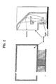
- a projector having a projector body for providing a light inclusive of a picture and a screen for displaying the light as shown in FIG. 1, or a projection TV as shown in FIG. 2 forms the picture on the screen, not by a light emitted from the panel itself, but by a light transmitted through, or reflected at the panel, a color sense of the picture can also be varied with luminance and chromaticity of the light projected thereto, a light from an external illumination, and reflectivity and color of the screen, substantially.
- the related art projection type display has a problem in that the picture quality deterioration can not be avoided because the abnormal variation of the luminance and chromaticity of the picture caused by the external illumination and screen characteristics can not be compensated.
- the present invention is directed to device and method for compensating a picture quality of a projection type display that substantially obviates one or more of the problems due to limitations and disadvantages of the related art.
- An object of the present invention is to provide device and method for compensating a picture quality of a projection type display, in which a picture quality is always compensated to an optimum state automatically regardless of factors giving influences to the picture quality, for prevention of a picture quality deterioration.
- the device for compensating a picture quality of a projection type display includes a screen for displaying a picture projected from outside of the screen, a video processing part for receiving, and converting an analog video signal into a digital video signal, and adjusting an offset and a gain thereof, for making the video signal displayable on the screen, a sensing part for sensing the video signal from the video processing part and projected to a region of the screen, a memory part for storing reference video information, and a microcomputer for projecting the reference video information stored at the memory part onto the screen through the video processing part according to a user's picture quality compensation command, or a preset algorithm, and controlling the video processing part so that a luminance and chromaticity of the picture are calculated according to an output of the sensing part, the luminance and the chromaticity of picture are compared to preset values, and a compensation is made according to a result of the comparison.
- a method for compensating a picture quality of a projection type display having a body and a screen including the steps of (a) the body projecting, and displaying a first reference picture on the screen, detecting a displayed picture, and calculating a chromaticity of the picture according to a user's command, or a preset algorithm, (b) increasing an offset value of a color signal in R/G/B color signals, which lacks chromaticity, until the offset value is within a normally allowable range if the chromaticity calculated for the first reference picture is within a correctable range, and outside of the normally allowable range, (c) the body projecting, and displaying a second reference picture on the screen, detecting a displayed picture, and calculating luminance and chromaticity of the displayed picture, and (d) increasing a luminance output level of the second reference picture to an optimal luminance step by step to complete a luminance compensation, and decreasing a gain of a color signal in the R/G
- a device for compensating a picture quality of a projection type display in accordance with a preferred embodiment of the present invention includes a projector body 100 for providing a light inclusive of a picture, and a screen 200 for displaying the light from the projector body 100, detecting an environmental light, and transmitting a detected value of the environmental light to the projector body 100 in an UV ray.
- optical detection/transmission part 210 fitted to a region of the screen 200 at which an environment light detection is easy, having an optical sensor and a UV transmitter for detection of the environmental light and transmission of a result of the detection to the body 100 in a UV form.
- the projector body 100 includes a video processing part 110 having a sampling part 111 for receiving and converting an analog video signal into a digital video signal, a digital video processing part 112 for adjusting an offset and a gain of the digital video signal from the sampling part 111, and a video presenting part 113 for presenting an output from the digital video processing part 112 as a displayable video signal, a projection lens 120 for projecting an output of the video processing part 110 to the screen 100, a memory part 130 for storing compensation reference video information, a sensing part 150 for detecting a luminance and a chromaticity of the compensation reference video displayed in a region of the screen 200, a UV receiving part 160 for receiving the UV signal from the optical detection/transmission part 210 and transferring to a microcomputer 140, and the microcomputer 140 for providing a control signal to the video processing part 110 for presenting the compensation reference video stored in the memory 130 according to a users command, a preset algorithm, or an environmental light detection value from the UV receiving part 160,
- the sensing part 150 includes an optical sensor 152 for converting the light incident thereon into an electrical signal, and a focusing lens system 151 for directing, and focusing a light displayed on the screen 200 onto the optical sensor 152.
- the video processing part 110 receives, and samples the analog video signal at fixed intervals, converts into a digital video signal, and adjusts offset and gain thereof, and processes the video signal to be displayable on the screen, and provides to the projection lens 120. Then, the projection lens 120 projects the picture on the screen.
- the optical detection/transmission part 210 in a region of the screen 200 detects an environmental light and converts into a UV signal, and transmits to the body 100.
- the UV ray receiving part 160 in the body 100 receives the UV signal, converts into an electrical signal, and transfers to the microcomputer 140.
- the microcomputer 140 stores an output of the UV ray receiving part 160 at the memory part 130, compares to a previous optical detection value stored already, and conducts a picture quality compensation operation according to a difference of the present optical detection value and the previous optical detection value. Other than the comparison of the optical detection values, the picture quality compensation operation may be carried out according to separate user's picture quality compensation command, or the like.
- black pattern video information is provided to a video processing part 110 from compensation reference video information (white pattern, and black pattern) stored in the memory part 130 for checking variation of luminance and chromaticity of the picture displayed on the screen 200 (S100).
- the black pattern video information is a minimum value of a digital data value processed in the video processing part 110.
- the video processing part 110 processes the compensation reference video information into a picture, and displays in a central part of the screen 200, or, as shown in FIGS. 6A or 6B, along a preset width of a periphery of the screen, or only in a part of the periphery.
- the picture is displayed as shown in FIGS. 6A or 6B for minimizing feeling of rejection of the user.
- the sensing part 150 focuses on the picture displayed in the central part, or as shown in FIG. 6A, or 6B.
- the sensing part 150 detects a light of the picture displayed on the screen 200, and transfers the detected value to the microcomputer 140.
- the microcomputer 140 detects a chromaticity of the picture displayed on the screen presently according to the detected value at the sensing part 150.
- the microcomputer 140 calculates the chromaticity by using the detected value at the sensing part 150, and determines the calculated chromaticity being within a correctable range (S110).
- the microcomputer 140 determines the calculated chromaticity being within a normally allowable range (S120). If the calculated chromaticity is not within the normally allowable range, i.e., abnormal, as a result of the determination (S120), an offset value of a color signal in R/G/B color signals which lacks a chromaticity value is increased (S130), because the black pattern video information is a minimum value of a digital data, and the chromaticity is calculated (S140) again at the sensing part 150, to return to the step (120).
- the digital video processing part 112 in the video processing part 110 increases an offset of a color signal in the digital video signals from the sampling part 111, which lacks chromaticity, and transfers to the video presenting part 113, and the video presenting part 113 processes the digital video signal having the increased offset value displayable on the screen, and displays on the screen 200 through the projection lens 120.
- the microcomputer 140 calculates chromaticity of the sensed video signal, and controls the video processing part 110 such that the chromaticity is within the allowable range.
- the microcomputer 140 makes the white pattern video information provided from the memory part 130 to the video processing part 110 (S150).
- the white pattern video information is a maximum value of the digital data processed in the video processing part 110.
- the video processing for the white pattern, display, and sensing of the displayed picture are identical to the case of the black pattern, of which detailed explanations will be omitted.
- the microcomputer 140 calculates the luminance of the white pattern picture through the signal sensed at the sensing part 150, increases a present luminance output level by one stage (S160), calculates the luminance of the picture detected at the sensing part 150, and determines an actual increase of the luminance (S170).
- the foregoing steps (S160), and (S170) are repeated until the luminance increases no more. That is, the luminance output level is increased step by step in succession until the present luminance reaches to an optimal level.
- an actual luminance change following the luminance output level change is determined (S171), determining that an original luminance is optimum if there is no actual luminance change following the luminance output level change, the luminance output level is returned to an original state, i.e., to a state one step before (S180). Opposite to this, if there is an actual luminance change following the luminance output level change, i.e., the luminance is optimized following conduction of the steps (S160) and (S170), the present luminance output level is maintained.
- the microcomputer 140 calculates chromaticity of the white pattern picture displayed on the screen presently by using a detection value at the sensing part 150, determines the calculated chromaticity of being within the allowable range (S200). If the calculated chromaticity is within the allowable range as a result of the determination (S200), it can be known that optimum luminance correction of the screen and optimum white level chromaticity correction following the luminance correction are made.
- the gain correction operation is made in the digital video processing part 112 in the video processing part 110 under the control of the microcomputer 140 by a method identical to the foregoing offset correction operation for the black pattern picture, a detailed explanation will be omitted.
- the microcomputer 140 controls such that the white pattern video information is provided from the memory part 130 (S230), and displayed on the screen 200 through the video processing part 110.
- the microcomputer 140 calculates chromaticity of the white pattern picture according to the output of the sensing part 150 (S240), and determines the calculated chromaticity within a correctable range (S250). If the calculated chromaticity is outside of the correctable range as a result of the determination (S250), a gain of a color signal in the R/G/B color signals, which has an excessive chromaticity, is reduced within the correctable range (S260). Opposite to this, if the calculated chromaticity is within the correctable range as a result of the determination (S250), the process returns to the step (S160), to make chromaticity correction for the luminance and the white pattern picture through the foregoing steps (S170 ⁇ S210).
- the foregoing embodiment of the present invention is a description of a system in which a variation of an environment light of a screen is sensed automatically, and a picture quality correction is made.
- the foregoing basic picture quality correction algorithm has no change even if the automatic sensing function is excluded (by changing the optical detection/transmission device at the screen, the UV ray receiver at the body, and the algorithm in the microcomputer), it can be known that the present invention is not limited to the present embodiment, but different variations are possible.
- the device and method for compensating a picture quality of a projection type display can provide an optimal picture quality to improve a product reliability of user regardless of environment illumination, because the environmental luminance variation is detected automatically, and optimal chromaticity and luminance correction are carried out, or the chromaticity and the luminance corrections are made manually in correspondence to the present luminance.
Landscapes
- Engineering & Computer Science (AREA)
- Multimedia (AREA)
- Signal Processing (AREA)
- Video Image Reproduction Devices For Color Tv Systems (AREA)
- Controls And Circuits For Display Device (AREA)
- Processing Of Color Television Signals (AREA)
- Projection Apparatus (AREA)
- Testing, Inspecting, Measuring Of Stereoscopic Televisions And Televisions (AREA)
- Control Of Indicators Other Than Cathode Ray Tubes (AREA)
- Transforming Electric Information Into Light Information (AREA)
Abstract
Description
Claims (18)
- A device for compensating a picture quality of a projection type display comprising:a screen for displaying a picture projected from outside of the screen;a video processing part for receiving, and converting an analog video signal into a digital video signal, and adjusting an offset and a gain thereof, for making the video signal displayable on the screen;a sensing part for sensing the video signal from the video processing part and projected to a region of the screen;a memory part for storing reference video information; and,a microcomputer for projecting the reference video information stored at the memory part onto the screen through the video processing part according to a user's picture quality compensation command, or a preset algorithm, and controlling the video processing part so that a luminance and chromaticity of the picture are calculated according to an output of the sensing part, the luminance and the chromaticity of picture are compared to preset values, and a compensation is made according to a result of the comparison.
- A device as claimed in claim 1, wherein the sensing part includes;a focusing lens focused on a region of the screen, andan optical sensor.
- A device as claimed in claim 1, wherein the reference video information in the memory part includes black pattern video information and white pattern video information.
- A device for compensating a picture quality of a projection type display comprising:a screen for displaying a picture projected from outside of the screen;an optical detection/transmission part for detecting an environmental light of the screen, and transmitting in a form of a UV ray;a video processing part for receiving, and converting an analog video signal into a digital video signal, and adjusting an offset and a gain thereof, for making the video signal displayable on the screen;a sensing part for sensing the video signal from the video processing part and projected to a region of the screen;a memory part for storing reference video information;a UV receiving part for receiving the UV ray signal from the optical detection /transmission part; and,a microcomputer for projecting the reference video information stored at the memory part onto the screen through the video processing part according to a user's picture quality compensation command, or a preset algorithm, and controlling the video processing part so that a luminance and chromaticity of the picture are calculated according to an output of the sensing part, the luminance and the chromaticity of picture are compared to preset values, and a compensation is made according to a result of the comparison.
- A device as claimed in claim 4, wherein the sensing part includes;a focusing lens focused on a region of the screen, andan optical sensor.
- A device as claimed in claim 4, wherein the reference video information in the memory part includes black pattern video information and white pattern video information.
- A device as claimed in claim 4, wherein the optical detection/transmission part is fitted to a region of the screen.
- A device as claimed in claim 4, wherein the optical detection/transmission part includes;an optical sensor for detecting an environmental light of the screen; and,a UV ray transmitter for converting the detected environment light into a form of a UV ray, and transmitting to the UV ray receiving part.
- A method for compensating a picture quality of a projection type display having a body and a screen, comprising the steps of:(a) the body projecting, and displaying a first reference picture on the screen, detecting a displayed picture, and calculating a chromaticity of the picture according to a user's command, or a preset algorithm;(b) increasing an offset value of a color signal in R/G/B color signals, which lacks chromaticity, until the offset value is within a normally allowable range if the chromaticity calculated for the first reference picture is within a correctable range, and outside of the normally allowable range;(c) the body projecting, and displaying a second reference picture on the screen, detecting a displayed picture, and calculating luminance and chromaticity of the displayed picture; and,(d) increasing a luminance output level of the second reference picture to an optimal luminance step by step to complete a luminance compensation, and decreasing a gain of a color signal in the R/G/B color signals, which has an excessive chromaticity, until the gain is within a normally allowable range if the chromaticity calculated for the second reference picture is outside of the normally allowable range, thereby completing the compensation.
- A method as claimed in claim 9, wherein the first reference picture is a black pattern, and the second reference picture is a white pattern.
- A method as claimed in claim 9, wherein the first reference picture and the second reference picture are displayed along a width of a periphery of the screen, respectively.
- A method as claimed in claim 9, wherein the first reference picture and the second reference picture are displayed in a part of a periphery of the screen, respectively.
- A method as claimed in claim 9, further comprising the step of increasing an offset of a color signal in the R/G/B color signals, which has an excessive chromaticity, until the offset reaches to a preset correctable range if the chromaticity calculated for the first reference picture is outside of the correctable range, thereby completing the compensation.
- A method as claimed in claim 9, further comprising the step of putting the luminance output level back to a value before the luminance output level is increased in a case there is no actual luminance increase following the increase of the luminance output level for the second reference picture.
- A method as claimed in claim 9, further comprising the step of decreasing a gain of a color signal in the R/G/B color signals, which has an excessive chromaticity, until the gain reaches to a preset correctable range if the chromaticity calculated for the second reference picture is outside of the correctable range, thereby completing the compensation.
- A method as claimed in claim 9, wherein the first reference picture is a minimum value of a digital data value, and the second reference picture is a maximum value of the digital data value.
- A method for compensating a picture quality of a projection type display having a body, a screen, and an optical detection/transmission means for detecting an environmental light of the screen and transmitting to the body, comprising the steps of:(a) the body projecting, and displaying a first reference picture on the screen, detecting a displayed picture, and calculating a chromaticity of the picture according to a variation of the environmental light of the screen;(b) increasing an offset value of a color signal in R/G/B color signals, which lacks chromaticity, until the offset value is within a normally allowable range if the chromaticity calculated for the first reference picture is within a correctable range, and outside of the normally allowable range;(c) the body projecting, and displaying a second reference picture on the screen, detecting a displayed picture, and calculating luminance and chromaticity of the displayed picture; and,(d) increasing a luminance output level of the second reference picture to an optimal luminance step by step to complete a luminance compensation, and decreasing a gain of a color signal in the R/G/B color signals, which has an excessive chromaticity, until the gain is within a normally allowable range if the chromaticity calculated for the second reference picture is outside of the normally allowable range, thereby completing the compensation.
- A method as claimed in claim 17, wherein the first reference picture is a black pattern, and the second reference picture is a white pattern.
Applications Claiming Priority (2)
| Application Number | Priority Date | Filing Date | Title |
|---|---|---|---|
| KR2001000980 | 2001-01-08 | ||
| KR10-2001-0000980A KR100396683B1 (en) | 2001-01-08 | 2001-01-08 | Method and apparatus for correcting screen brightness/chromaticity of TV |
Publications (3)
| Publication Number | Publication Date |
|---|---|
| EP1223753A2 true EP1223753A2 (en) | 2002-07-17 |
| EP1223753A3 EP1223753A3 (en) | 2003-06-04 |
| EP1223753B1 EP1223753B1 (en) | 2010-07-21 |
Family
ID=19704378
Family Applications (1)
| Application Number | Title | Priority Date | Filing Date |
|---|---|---|---|
| EP02075039A Expired - Lifetime EP1223753B1 (en) | 2001-01-08 | 2002-01-07 | Method and device for compensating picture quality of projection type display |
Country Status (7)
| Country | Link |
|---|---|
| US (1) | US7050121B2 (en) |
| EP (1) | EP1223753B1 (en) |
| JP (1) | JP3701609B2 (en) |
| KR (1) | KR100396683B1 (en) |
| CN (1) | CN1237820C (en) |
| AT (1) | ATE475262T1 (en) |
| DE (1) | DE60237055D1 (en) |
Cited By (4)
| Publication number | Priority date | Publication date | Assignee | Title |
|---|---|---|---|---|
| EP1478192A3 (en) * | 2003-05-16 | 2006-02-01 | Seiko Epson Corporation | Image processing system, projector, information storage medium, and image processing method |
| EP1760524A1 (en) * | 2005-08-29 | 2007-03-07 | LG Electronics Inc. | Method of controlling projection-type display device and projection-type display device using the same |
| CN101155312B (en) * | 2003-05-16 | 2010-12-15 | 精工爱普生株式会社 | Image processing system, projector, and image processing method |
| EP1804518A3 (en) * | 2005-12-29 | 2012-12-12 | Samsung Electronics Co., Ltd. | Method and device for adjusting image color in image projector |
Families Citing this family (40)
| Publication number | Priority date | Publication date | Assignee | Title |
|---|---|---|---|---|
| JP3719411B2 (en) * | 2001-05-31 | 2005-11-24 | セイコーエプソン株式会社 | Image display system, projector, program, information storage medium, and image processing method |
| JP3924755B2 (en) * | 2001-09-13 | 2007-06-06 | 本田技研工業株式会社 | High-speed event imaging device |
| KR100852666B1 (en) * | 2002-01-21 | 2008-08-19 | 엘지전자 주식회사 | Luminance Correction Apparatus and Method for Image Display |
| US7391475B2 (en) * | 2002-01-31 | 2008-06-24 | Hewlett-Packard Development Company, L.P. | Display image generation with differential illumination |
| JP3514257B2 (en) * | 2002-05-20 | 2004-03-31 | セイコーエプソン株式会社 | Image processing system, projector, image processing method, program, and information storage medium |
| JP4009850B2 (en) | 2002-05-20 | 2007-11-21 | セイコーエプソン株式会社 | Projection-type image display system, projector, program, information storage medium, and image projection method |
| US7266778B2 (en) * | 2002-10-02 | 2007-09-04 | Hewlett-Packard Development Company, L.P. | Freezable projection display |
| JP2004228948A (en) | 2003-01-23 | 2004-08-12 | Seiko Epson Corp | Image processing system, projector, program, information storage medium, and image processing method |
| KR100514749B1 (en) * | 2003-05-21 | 2005-09-14 | 삼성전자주식회사 | Apparatus and method for auto calibration of display device |
| KR100547121B1 (en) | 2003-06-14 | 2006-01-26 | 삼성전자주식회사 | Apparatus and method for adjusting convergence of projection television |
| US7581841B2 (en) | 2004-03-19 | 2009-09-01 | Nec Display Solutions, Ltd. | Luminance correcting apparatus, luminance correcting method, and projector |
| KR100601674B1 (en) * | 2004-05-11 | 2006-07-14 | 삼성전자주식회사 | Image display device and projection TV set employing the same |
| KR100612010B1 (en) * | 2004-05-14 | 2006-08-11 | 삼성전자주식회사 | Two-stage image forming apparatus and projection TV set using the same |
| CN1326388C (en) * | 2004-05-25 | 2007-07-11 | 英保达股份有限公司 | Digital image quality inspection method and system |
| US7808556B2 (en) * | 2004-11-08 | 2010-10-05 | Thomson Licensing | Image processing device |
| WO2006074103A1 (en) * | 2005-01-05 | 2006-07-13 | Tte Technology, Inc. | Display device with speaker grill |
| US20080192154A1 (en) * | 2005-01-05 | 2008-08-14 | Michel Alain Jean Marie Cadio | System And Method For Mounting A Television Screen |
| CN1327691C (en) * | 2005-02-23 | 2007-07-18 | 南京Lg新港显示有限公司 | Picture regulator for picture apparatus and its method |
| CN100433126C (en) * | 2005-09-06 | 2008-11-12 | 台达电子工业股份有限公司 | Display device and method capable of enhancing image contrast |
| JP4626497B2 (en) * | 2005-11-24 | 2011-02-09 | 株式会社日立製作所 | Video processing device and portable terminal device |
| JP2007150480A (en) * | 2005-11-24 | 2007-06-14 | Funai Electric Co Ltd | Liquid crystal television adjustment system, liquid crystal display adjustment system, and liquid crystal display |
| KR100738662B1 (en) * | 2005-12-01 | 2007-07-11 | 주식회사 대우일렉트로닉스 | How to adjust auto white balance using light sensor |
| KR100771638B1 (en) | 2006-07-28 | 2007-10-31 | 엘지전자 주식회사 | Image quality control system and control method |
| KR100866882B1 (en) * | 2007-03-14 | 2008-11-04 | 엘지전자 주식회사 | Image processing apparatus, projector using same and image processing method thereof |
| CN101384114B (en) * | 2007-09-07 | 2012-01-25 | 比亚迪股份有限公司 | Light source control system and light source box |
| CN101399032B (en) * | 2007-09-25 | 2011-09-14 | 中强光电股份有限公司 | Display device with brightness and color temperature control system and brightness and color temperature control method |
| US8979277B2 (en) * | 2008-05-02 | 2015-03-17 | Thomson Licensing | Method, apparatus and system for automated color management in digital cinema |
| JP5235551B2 (en) * | 2008-07-31 | 2013-07-10 | キヤノン株式会社 | Image processing apparatus and method |
| KR101509247B1 (en) * | 2008-09-08 | 2015-04-06 | 엘지전자 주식회사 | A projector and A method of image revision |
| US8195054B2 (en) * | 2008-11-26 | 2012-06-05 | Samsung Electronics Co., Ltd | Apparatus and method for transmitting and receiving an information symbol in a visible light communication system for color code modulation |
| KR101147422B1 (en) | 2010-01-05 | 2012-05-24 | 삼성모바일디스플레이주식회사 | Apparatus for x-ray detecting and method for x-ray detecting |
| KR101341025B1 (en) | 2010-08-11 | 2013-12-13 | 엘지디스플레이 주식회사 | Simulation method for image quality improvement of image display device and circuit the same |
| JP2013219452A (en) * | 2012-04-05 | 2013-10-24 | Sony Corp | Color signal processing circuit, color signal processing method, color reproduction evaluation method, imaging apparatus, electronic apparatus and testing apparatus |
| US9875724B2 (en) * | 2012-08-21 | 2018-01-23 | Beijing Lenovo Software Ltd. | Method and electronic device for adjusting display |
| US20150033034A1 (en) * | 2013-07-23 | 2015-01-29 | Gideon Gerzon | Measuring a secure enclave |
| JP2017068058A (en) * | 2015-09-30 | 2017-04-06 | ソニー株式会社 | Image processing apparatus, image processing method, and program |
| KR102545758B1 (en) | 2016-09-12 | 2023-06-20 | 삼성전자주식회사 | Display apparatus and control method thereof |
| CN112086064B (en) * | 2020-09-22 | 2022-04-26 | 禹创半导体(深圳)有限公司 | Method for applying MIPI instruction comparison mechanism to backlight adjustment |
| CN118138731A (en) * | 2022-12-02 | 2024-06-04 | 台达电子工业股份有限公司 | Projection system and correction method thereof |
| CN119516956B (en) * | 2023-08-29 | 2025-12-12 | 华为技术有限公司 | Image display method, electronic device, and computer-readable storage medium |
Family Cites Families (21)
| Publication number | Priority date | Publication date | Assignee | Title |
|---|---|---|---|---|
| FR2660090B1 (en) * | 1990-03-23 | 1994-07-29 | Thomson Csf | DEVICE FOR VIEWING BY PROJECTION WITH A FEEDBACK LOOP FOR CORRECTING ALL OF THE DEFECTS IN THE PROJECTED IMAGE. |
| JPH05127620A (en) * | 1991-11-06 | 1993-05-25 | Matsushita Electric Ind Co Ltd | Method and circuit for adjusting liquid crystal projection type color display |
| JPH0698346A (en) * | 1992-09-11 | 1994-04-08 | Matsushita Electric Ind Co Ltd | White balance automatic adjustment device |
| JPH06138849A (en) | 1992-10-30 | 1994-05-20 | Sharp Corp | Liquid crystal video display device |
| JPH07264620A (en) * | 1994-03-18 | 1995-10-13 | Hitachi Ltd | Image reproducing method and apparatus thereof |
| JPH0856366A (en) | 1994-06-07 | 1996-02-27 | Mitsubishi Electric Corp | Projection display device and adjusting method thereof |
| JPH0879787A (en) | 1994-09-05 | 1996-03-22 | Toshiba Corp | Color image display device |
| EP0746798A1 (en) * | 1994-12-22 | 1996-12-11 | Koninklijke Philips Electronics N.V. | Presentation system with overhead projector |
| US5793441A (en) * | 1995-06-07 | 1998-08-11 | Hughes-Jvc Technology Corporation | Method and apparatus for measuring illumination uniformity of a liquid crystal light valve projector |
| JPH0937281A (en) | 1995-07-18 | 1997-02-07 | Matsushita Electric Ind Co Ltd | Auto white balance circuit |
| JPH0984036A (en) * | 1995-09-20 | 1997-03-28 | Hitachi Ltd | Projection display device, multi-display device using the same, and multi-display system |
| JPH09281921A (en) * | 1996-04-16 | 1997-10-31 | Matsushita Electric Ind Co Ltd | Image display device |
| KR19990065540A (en) * | 1998-01-14 | 1999-08-05 | 구자홍 | TV (TV) quality control device and method |
| US6340976B1 (en) * | 1998-04-15 | 2002-01-22 | Mitsubishi Denki Kabushiki Kaisha | Multivision system, color calibration method and display |
| KR20000009068U (en) * | 1998-10-30 | 2000-05-25 | 전주범 | Screen Color Adjuster on Projection Televisions |
| KR100299967B1 (en) * | 1999-01-26 | 2001-09-26 | 윤종용 | Apparatus for controlling light capacity in liquid crystal display projection television |
| KR20010001597U (en) * | 1999-06-30 | 2001-01-15 | 윤종용 | An apparatus for image quality improvement using optical sensor |
| US6297859B1 (en) * | 1999-06-30 | 2001-10-02 | Thomson Licensing S.A. | Opto sensor signal detector |
| CN1318156A (en) * | 1999-07-20 | 2001-10-17 | 皇家菲利浦电子有限公司 | Method and device for white balance adjustment |
| JP2001060082A (en) * | 1999-08-24 | 2001-03-06 | Matsushita Electric Ind Co Ltd | Color reproduction terminal device and network color reproduction system |
| JP2000358253A (en) * | 2000-01-01 | 2000-12-26 | Hitachi Ltd | Display using color picture tube with automatic white balance adjustment circuit |
-
2001
- 2001-01-08 KR KR10-2001-0000980A patent/KR100396683B1/en not_active Expired - Fee Related
-
2002
- 2002-01-07 EP EP02075039A patent/EP1223753B1/en not_active Expired - Lifetime
- 2002-01-07 DE DE60237055T patent/DE60237055D1/en not_active Expired - Lifetime
- 2002-01-07 AT AT02075039T patent/ATE475262T1/en not_active IP Right Cessation
- 2002-01-08 US US10/038,671 patent/US7050121B2/en not_active Expired - Fee Related
- 2002-01-08 CN CNB021031681A patent/CN1237820C/en not_active Expired - Fee Related
- 2002-01-08 JP JP2002001760A patent/JP3701609B2/en not_active Expired - Fee Related
Cited By (8)
| Publication number | Priority date | Publication date | Assignee | Title |
|---|---|---|---|---|
| EP1478192A3 (en) * | 2003-05-16 | 2006-02-01 | Seiko Epson Corporation | Image processing system, projector, information storage medium, and image processing method |
| US7061506B2 (en) | 2003-05-16 | 2006-06-13 | Seiko Epson Corporation | Image processing system, projector, program, information storage medium, and image processing method |
| US7245307B2 (en) | 2003-05-16 | 2007-07-17 | Seiko Epson Corporation | Image processing system, projector, information storage medium, and image processing method |
| US7417643B2 (en) | 2003-05-16 | 2008-08-26 | Seiko Epson Corporation | Image processing system, projector, storage medium, and image processing method |
| CN100426325C (en) * | 2003-05-16 | 2008-10-15 | 精工爱普生株式会社 | Image processing system, projector, and image processing method |
| CN101155312B (en) * | 2003-05-16 | 2010-12-15 | 精工爱普生株式会社 | Image processing system, projector, and image processing method |
| EP1760524A1 (en) * | 2005-08-29 | 2007-03-07 | LG Electronics Inc. | Method of controlling projection-type display device and projection-type display device using the same |
| EP1804518A3 (en) * | 2005-12-29 | 2012-12-12 | Samsung Electronics Co., Ltd. | Method and device for adjusting image color in image projector |
Also Published As
| Publication number | Publication date |
|---|---|
| EP1223753A3 (en) | 2003-06-04 |
| JP2002281520A (en) | 2002-09-27 |
| CN1364034A (en) | 2002-08-14 |
| ATE475262T1 (en) | 2010-08-15 |
| US20020089611A1 (en) | 2002-07-11 |
| JP3701609B2 (en) | 2005-10-05 |
| KR100396683B1 (en) | 2003-09-03 |
| DE60237055D1 (en) | 2010-09-02 |
| EP1223753B1 (en) | 2010-07-21 |
| US7050121B2 (en) | 2006-05-23 |
| CN1237820C (en) | 2006-01-18 |
| KR20020059540A (en) | 2002-07-13 |
Similar Documents
| Publication | Publication Date | Title |
|---|---|---|
| EP1223753A2 (en) | Method and device for compensating picture quality of projection type display | |
| US6727489B2 (en) | Automatic image-quality adjustment system | |
| US6292228B1 (en) | Device and method for auto-adjustment of image condition in display using data representing both brightness or contrast and color temperature | |
| US6002386A (en) | Automatic contrast control of display device | |
| US20180012561A1 (en) | Display apparatus and control method thereof | |
| US7576750B2 (en) | Method and arrangement for optimizing a luminance characteristic curve | |
| KR100201021B1 (en) | Image quality control device | |
| US20020158825A1 (en) | Liquid crystal projector apparatus and driving method for liquid crystal projector apparatus | |
| US20130342817A1 (en) | Image display device and image adjustment method | |
| CN101383977A (en) | projection display device | |
| JPH1090645A (en) | Liquid crystal display | |
| JPH04367189A (en) | White balance adjuster | |
| JP2002351445A (en) | Display device | |
| US20090207312A1 (en) | Video processing apparatus and method for processing video signal | |
| US20100123696A1 (en) | Image display apparatus and method | |
| US20020051086A1 (en) | Luminance correction system used in a vision system | |
| US7809209B2 (en) | Image display device, and control method for the same | |
| US7293883B2 (en) | Projector and pattern image display method | |
| US5293224A (en) | White balance control system | |
| EP0440216B1 (en) | White balance control system | |
| KR970022496A (en) | Photo printing device | |
| US20070046908A1 (en) | Method of controlling projection-type display device and projection-type display device using the same | |
| KR100629529B1 (en) | Projector automatic brightness adjustment method and method | |
| KR100517309B1 (en) | A projection image display system for automatically controlling brightness and method thereof | |
| US20060176408A1 (en) | Method of displaying video during auto-convergence |
Legal Events
| Date | Code | Title | Description |
|---|---|---|---|
| PUAI | Public reference made under article 153(3) epc to a published international application that has entered the european phase |
Free format text: ORIGINAL CODE: 0009012 |
|
| AK | Designated contracting states |
Kind code of ref document: A2 Designated state(s): AT BE CH CY DE DK ES FI FR GB GR IE IT LI LU MC NL PT SE TR |
|
| AX | Request for extension of the european patent |
Free format text: AL;LT;LV;MK;RO;SI |
|
| PUAL | Search report despatched |
Free format text: ORIGINAL CODE: 0009013 |
|
| AK | Designated contracting states |
Designated state(s): AT BE CH CY DE DK ES FI FR GB GR IE IT LI LU MC NL PT SE TR |
|
| AX | Request for extension of the european patent |
Extension state: AL LT LV MK RO SI |
|
| RIC1 | Information provided on ipc code assigned before grant |
Ipc: 7H 04N 5/74 A Ipc: 7H 04N 17/00 B Ipc: 7H 04N 1/60 B |
|
| 17P | Request for examination filed |
Effective date: 20031203 |
|
| AKX | Designation fees paid |
Designated state(s): AT BE CH CY DE DK ES FI FR GB GR IE IT LI LU MC NL PT SE TR |
|
| 17Q | First examination report despatched |
Effective date: 20061115 |
|
| GRAP | Despatch of communication of intention to grant a patent |
Free format text: ORIGINAL CODE: EPIDOSNIGR1 |
|
| GRAS | Grant fee paid |
Free format text: ORIGINAL CODE: EPIDOSNIGR3 |
|
| GRAA | (expected) grant |
Free format text: ORIGINAL CODE: 0009210 |
|
| AK | Designated contracting states |
Kind code of ref document: B1 Designated state(s): AT BE CH CY DE DK ES FI FR GB GR IE IT LI LU MC NL PT SE TR |
|
| REG | Reference to a national code |
Ref country code: GB Ref legal event code: FG4D |
|
| REG | Reference to a national code |
Ref country code: CH Ref legal event code: EP |
|
| REG | Reference to a national code |
Ref country code: IE Ref legal event code: FG4D |
|
| REF | Corresponds to: |
Ref document number: 60237055 Country of ref document: DE Date of ref document: 20100902 Kind code of ref document: P |
|
| REG | Reference to a national code |
Ref country code: NL Ref legal event code: T3 |
|
| PG25 | Lapsed in a contracting state [announced via postgrant information from national office to epo] |
Ref country code: FI Free format text: LAPSE BECAUSE OF FAILURE TO SUBMIT A TRANSLATION OF THE DESCRIPTION OR TO PAY THE FEE WITHIN THE PRESCRIBED TIME-LIMIT Effective date: 20100721 Ref country code: AT Free format text: LAPSE BECAUSE OF FAILURE TO SUBMIT A TRANSLATION OF THE DESCRIPTION OR TO PAY THE FEE WITHIN THE PRESCRIBED TIME-LIMIT Effective date: 20100721 |
|
| PG25 | Lapsed in a contracting state [announced via postgrant information from national office to epo] |
Ref country code: PT Free format text: LAPSE BECAUSE OF FAILURE TO SUBMIT A TRANSLATION OF THE DESCRIPTION OR TO PAY THE FEE WITHIN THE PRESCRIBED TIME-LIMIT Effective date: 20101122 Ref country code: CY Free format text: LAPSE BECAUSE OF FAILURE TO SUBMIT A TRANSLATION OF THE DESCRIPTION OR TO PAY THE FEE WITHIN THE PRESCRIBED TIME-LIMIT Effective date: 20100721 |
|
| PG25 | Lapsed in a contracting state [announced via postgrant information from national office to epo] |
Ref country code: GR Free format text: LAPSE BECAUSE OF FAILURE TO SUBMIT A TRANSLATION OF THE DESCRIPTION OR TO PAY THE FEE WITHIN THE PRESCRIBED TIME-LIMIT Effective date: 20101022 Ref country code: BE Free format text: LAPSE BECAUSE OF FAILURE TO SUBMIT A TRANSLATION OF THE DESCRIPTION OR TO PAY THE FEE WITHIN THE PRESCRIBED TIME-LIMIT Effective date: 20100721 Ref country code: SE Free format text: LAPSE BECAUSE OF FAILURE TO SUBMIT A TRANSLATION OF THE DESCRIPTION OR TO PAY THE FEE WITHIN THE PRESCRIBED TIME-LIMIT Effective date: 20100721 |
|
| PG25 | Lapsed in a contracting state [announced via postgrant information from national office to epo] |
Ref country code: DK Free format text: LAPSE BECAUSE OF FAILURE TO SUBMIT A TRANSLATION OF THE DESCRIPTION OR TO PAY THE FEE WITHIN THE PRESCRIBED TIME-LIMIT Effective date: 20100721 |
|
| PLBE | No opposition filed within time limit |
Free format text: ORIGINAL CODE: 0009261 |
|
| STAA | Information on the status of an ep patent application or granted ep patent |
Free format text: STATUS: NO OPPOSITION FILED WITHIN TIME LIMIT |
|
| PG25 | Lapsed in a contracting state [announced via postgrant information from national office to epo] |
Ref country code: IT Free format text: LAPSE BECAUSE OF FAILURE TO SUBMIT A TRANSLATION OF THE DESCRIPTION OR TO PAY THE FEE WITHIN THE PRESCRIBED TIME-LIMIT Effective date: 20100721 |
|
| 26N | No opposition filed |
Effective date: 20110426 |
|
| PG25 | Lapsed in a contracting state [announced via postgrant information from national office to epo] |
Ref country code: ES Free format text: LAPSE BECAUSE OF FAILURE TO SUBMIT A TRANSLATION OF THE DESCRIPTION OR TO PAY THE FEE WITHIN THE PRESCRIBED TIME-LIMIT Effective date: 20101101 |
|
| REG | Reference to a national code |
Ref country code: DE Ref legal event code: R097 Ref document number: 60237055 Country of ref document: DE Effective date: 20110426 |
|
| PG25 | Lapsed in a contracting state [announced via postgrant information from national office to epo] |
Ref country code: MC Free format text: LAPSE BECAUSE OF NON-PAYMENT OF DUE FEES Effective date: 20110131 |
|
| REG | Reference to a national code |
Ref country code: CH Ref legal event code: PL |
|
| REG | Reference to a national code |
Ref country code: IE Ref legal event code: MM4A |
|
| PG25 | Lapsed in a contracting state [announced via postgrant information from national office to epo] |
Ref country code: LI Free format text: LAPSE BECAUSE OF NON-PAYMENT OF DUE FEES Effective date: 20110131 Ref country code: CH Free format text: LAPSE BECAUSE OF NON-PAYMENT OF DUE FEES Effective date: 20110131 |
|
| PG25 | Lapsed in a contracting state [announced via postgrant information from national office to epo] |
Ref country code: IE Free format text: LAPSE BECAUSE OF NON-PAYMENT OF DUE FEES Effective date: 20110107 |
|
| PGFP | Annual fee paid to national office [announced via postgrant information from national office to epo] |
Ref country code: GB Payment date: 20121213 Year of fee payment: 12 |
|
| PGFP | Annual fee paid to national office [announced via postgrant information from national office to epo] |
Ref country code: DE Payment date: 20121213 Year of fee payment: 12 Ref country code: FR Payment date: 20130123 Year of fee payment: 12 |
|
| PG25 | Lapsed in a contracting state [announced via postgrant information from national office to epo] |
Ref country code: LU Free format text: LAPSE BECAUSE OF NON-PAYMENT OF DUE FEES Effective date: 20110107 |
|
| PGFP | Annual fee paid to national office [announced via postgrant information from national office to epo] |
Ref country code: NL Payment date: 20121213 Year of fee payment: 12 |
|
| PG25 | Lapsed in a contracting state [announced via postgrant information from national office to epo] |
Ref country code: TR Free format text: LAPSE BECAUSE OF FAILURE TO SUBMIT A TRANSLATION OF THE DESCRIPTION OR TO PAY THE FEE WITHIN THE PRESCRIBED TIME-LIMIT Effective date: 20100721 |
|
| REG | Reference to a national code |
Ref country code: DE Ref legal event code: R119 Ref document number: 60237055 Country of ref document: DE |
|
| REG | Reference to a national code |
Ref country code: NL Ref legal event code: V1 Effective date: 20140801 |
|
| GBPC | Gb: european patent ceased through non-payment of renewal fee |
Effective date: 20140107 |
|
| PG25 | Lapsed in a contracting state [announced via postgrant information from national office to epo] |
Ref country code: NL Free format text: LAPSE BECAUSE OF NON-PAYMENT OF DUE FEES Effective date: 20140801 Ref country code: DE Free format text: LAPSE BECAUSE OF NON-PAYMENT OF DUE FEES Effective date: 20140801 |
|
| REG | Reference to a national code |
Ref country code: FR Ref legal event code: ST Effective date: 20140930 |
|
| REG | Reference to a national code |
Ref country code: DE Ref legal event code: R119 Ref document number: 60237055 Country of ref document: DE Effective date: 20140801 |
|
| PG25 | Lapsed in a contracting state [announced via postgrant information from national office to epo] |
Ref country code: GB Free format text: LAPSE BECAUSE OF NON-PAYMENT OF DUE FEES Effective date: 20140107 Ref country code: FR Free format text: LAPSE BECAUSE OF NON-PAYMENT OF DUE FEES Effective date: 20140131 |