JP4626497B2 - Video processing device and portable terminal device - Google Patents
Video processing device and portable terminal device Download PDFInfo
- Publication number
- JP4626497B2 JP4626497B2 JP2005338000A JP2005338000A JP4626497B2 JP 4626497 B2 JP4626497 B2 JP 4626497B2 JP 2005338000 A JP2005338000 A JP 2005338000A JP 2005338000 A JP2005338000 A JP 2005338000A JP 4626497 B2 JP4626497 B2 JP 4626497B2
- Authority
- JP
- Japan
- Prior art keywords
- input
- unit
- luminance
- correction
- feature point
- Prior art date
- Legal status (The legal status is an assumption and is not a legal conclusion. Google has not performed a legal analysis and makes no representation as to the accuracy of the status listed.)
- Active
Links
- 238000012545 processing Methods 0.000 title claims abstract description 56
- 238000001514 detection method Methods 0.000 claims description 141
- 238000012937 correction Methods 0.000 claims description 106
- 239000007787 solid Substances 0.000 claims 2
- 238000000034 method Methods 0.000 description 58
- 230000008569 process Effects 0.000 description 52
- 230000008859 change Effects 0.000 description 25
- 238000006243 chemical reaction Methods 0.000 description 24
- 238000010586 diagram Methods 0.000 description 20
- 230000006872 improvement Effects 0.000 description 13
- 238000004891 communication Methods 0.000 description 6
- XUIMIQQOPSSXEZ-UHFFFAOYSA-N Silicon Chemical compound [Si] XUIMIQQOPSSXEZ-UHFFFAOYSA-N 0.000 description 4
- 230000004075 alteration Effects 0.000 description 4
- 238000004364 calculation method Methods 0.000 description 3
- 230000006835 compression Effects 0.000 description 3
- 238000007906 compression Methods 0.000 description 3
- 238000005286 illumination Methods 0.000 description 3
- 229910052710 silicon Inorganic materials 0.000 description 3
- 239000010703 silicon Substances 0.000 description 3
- 230000008901 benefit Effects 0.000 description 2
- 230000007613 environmental effect Effects 0.000 description 2
- 230000006870 function Effects 0.000 description 2
- 230000007704 transition Effects 0.000 description 2
- PEDCQBHIVMGVHV-UHFFFAOYSA-N Glycerine Chemical compound OCC(O)CO PEDCQBHIVMGVHV-UHFFFAOYSA-N 0.000 description 1
- HBBGRARXTFLTSG-UHFFFAOYSA-N Lithium ion Chemical compound [Li+] HBBGRARXTFLTSG-UHFFFAOYSA-N 0.000 description 1
- 230000001413 cellular effect Effects 0.000 description 1
- 239000003086 colorant Substances 0.000 description 1
- 230000006837 decompression Effects 0.000 description 1
- 230000007423 decrease Effects 0.000 description 1
- 230000003247 decreasing effect Effects 0.000 description 1
- 239000000284 extract Substances 0.000 description 1
- 238000003780 insertion Methods 0.000 description 1
- 230000037431 insertion Effects 0.000 description 1
- 238000007689 inspection Methods 0.000 description 1
- 229910001416 lithium ion Inorganic materials 0.000 description 1
- 229910052987 metal hydride Inorganic materials 0.000 description 1
- 229910052759 nickel Inorganic materials 0.000 description 1
- PXHVJJICTQNCMI-UHFFFAOYSA-N nickel Substances [Ni] PXHVJJICTQNCMI-UHFFFAOYSA-N 0.000 description 1
- -1 nickel metal hydride Chemical class 0.000 description 1
- 238000003672 processing method Methods 0.000 description 1
- 230000004044 response Effects 0.000 description 1
- 238000005070 sampling Methods 0.000 description 1
- 238000000926 separation method Methods 0.000 description 1
- 238000012546 transfer Methods 0.000 description 1
Images


Classifications
-
- G—PHYSICS
- G09—EDUCATION; CRYPTOGRAPHY; DISPLAY; ADVERTISING; SEALS
- G09G—ARRANGEMENTS OR CIRCUITS FOR CONTROL OF INDICATING DEVICES USING STATIC MEANS TO PRESENT VARIABLE INFORMATION
- G09G5/00—Control arrangements or circuits for visual indicators common to cathode-ray tube indicators and other visual indicators
-
- H—ELECTRICITY
- H04—ELECTRIC COMMUNICATION TECHNIQUE
- H04N—PICTORIAL COMMUNICATION, e.g. TELEVISION
- H04N9/00—Details of colour television systems
- H04N9/64—Circuits for processing colour signals
- H04N9/68—Circuits for processing colour signals for controlling the amplitude of colour signals, e.g. automatic chroma control circuits
-
- H—ELECTRICITY
- H04—ELECTRIC COMMUNICATION TECHNIQUE
- H04B—TRANSMISSION
- H04B1/00—Details of transmission systems, not covered by a single one of groups H04B3/00 - H04B13/00; Details of transmission systems not characterised by the medium used for transmission
- H04B1/38—Transceivers, i.e. devices in which transmitter and receiver form a structural unit and in which at least one part is used for functions of transmitting and receiving
- H04B1/40—Circuits
-
- H—ELECTRICITY
- H04—ELECTRIC COMMUNICATION TECHNIQUE
- H04N—PICTORIAL COMMUNICATION, e.g. TELEVISION
- H04N21/00—Selective content distribution, e.g. interactive television or video on demand [VOD]
- H04N21/40—Client devices specifically adapted for the reception of or interaction with content, e.g. set-top-box [STB]; Operations thereof
- H04N21/41—Structure of client; Structure of client peripherals
- H04N21/414—Specialised client platforms, e.g. receiver in car or embedded in a mobile appliance
- H04N21/41407—Specialised client platforms, e.g. receiver in car or embedded in a mobile appliance embedded in a portable device, e.g. video client on a mobile phone, PDA, laptop
-
- H—ELECTRICITY
- H04—ELECTRIC COMMUNICATION TECHNIQUE
- H04N—PICTORIAL COMMUNICATION, e.g. TELEVISION
- H04N21/00—Selective content distribution, e.g. interactive television or video on demand [VOD]
- H04N21/40—Client devices specifically adapted for the reception of or interaction with content, e.g. set-top-box [STB]; Operations thereof
- H04N21/43—Processing of content or additional data, e.g. demultiplexing additional data from a digital video stream; Elementary client operations, e.g. monitoring of home network or synchronising decoder's clock; Client middleware
- H04N21/431—Generation of visual interfaces for content selection or interaction; Content or additional data rendering
- H04N21/4318—Generation of visual interfaces for content selection or interaction; Content or additional data rendering by altering the content in the rendering process, e.g. blanking, blurring or masking an image region
-
- H—ELECTRICITY
- H04—ELECTRIC COMMUNICATION TECHNIQUE
- H04N—PICTORIAL COMMUNICATION, e.g. TELEVISION
- H04N21/00—Selective content distribution, e.g. interactive television or video on demand [VOD]
- H04N21/40—Client devices specifically adapted for the reception of or interaction with content, e.g. set-top-box [STB]; Operations thereof
- H04N21/43—Processing of content or additional data, e.g. demultiplexing additional data from a digital video stream; Elementary client operations, e.g. monitoring of home network or synchronising decoder's clock; Client middleware
- H04N21/44—Processing of video elementary streams, e.g. splicing a video clip retrieved from local storage with an incoming video stream, rendering scenes according to MPEG-4 scene graphs
- H04N21/44008—Processing of video elementary streams, e.g. splicing a video clip retrieved from local storage with an incoming video stream, rendering scenes according to MPEG-4 scene graphs involving operations for analysing video streams, e.g. detecting features or characteristics in the video stream
-
- H—ELECTRICITY
- H04—ELECTRIC COMMUNICATION TECHNIQUE
- H04N—PICTORIAL COMMUNICATION, e.g. TELEVISION
- H04N5/00—Details of television systems
- H04N5/14—Picture signal circuitry for video frequency region
-
- H—ELECTRICITY
- H04—ELECTRIC COMMUNICATION TECHNIQUE
- H04N—PICTORIAL COMMUNICATION, e.g. TELEVISION
- H04N5/00—Details of television systems
- H04N5/14—Picture signal circuitry for video frequency region
- H04N5/20—Circuitry for controlling amplitude response
-
- H—ELECTRICITY
- H04—ELECTRIC COMMUNICATION TECHNIQUE
- H04N—PICTORIAL COMMUNICATION, e.g. TELEVISION
- H04N5/00—Details of television systems
- H04N5/44—Receiver circuitry for the reception of television signals according to analogue transmission standards
- H04N5/445—Receiver circuitry for the reception of television signals according to analogue transmission standards for displaying additional information
-
- H—ELECTRICITY
- H04—ELECTRIC COMMUNICATION TECHNIQUE
- H04N—PICTORIAL COMMUNICATION, e.g. TELEVISION
- H04N7/00—Television systems
- H04N7/01—Conversion of standards, e.g. involving analogue television standards or digital television standards processed at pixel level
- H04N7/0117—Conversion of standards, e.g. involving analogue television standards or digital television standards processed at pixel level involving conversion of the spatial resolution of the incoming video signal
- H04N7/0122—Conversion of standards, e.g. involving analogue television standards or digital television standards processed at pixel level involving conversion of the spatial resolution of the incoming video signal the input and the output signals having different aspect ratios
-
- H—ELECTRICITY
- H04—ELECTRIC COMMUNICATION TECHNIQUE
- H04N—PICTORIAL COMMUNICATION, e.g. TELEVISION
- H04N5/00—Details of television systems
- H04N5/44—Receiver circuitry for the reception of television signals according to analogue transmission standards
- H04N5/57—Control of contrast or brightness
- H04N5/58—Control of contrast or brightness in dependence upon ambient light
-
- Y—GENERAL TAGGING OF NEW TECHNOLOGICAL DEVELOPMENTS; GENERAL TAGGING OF CROSS-SECTIONAL TECHNOLOGIES SPANNING OVER SEVERAL SECTIONS OF THE IPC; TECHNICAL SUBJECTS COVERED BY FORMER USPC CROSS-REFERENCE ART COLLECTIONS [XRACs] AND DIGESTS
- Y10—TECHNICAL SUBJECTS COVERED BY FORMER USPC
- Y10S—TECHNICAL SUBJECTS COVERED BY FORMER USPC CROSS-REFERENCE ART COLLECTIONS [XRACs] AND DIGESTS
- Y10S348/00—Television
- Y10S348/913—Letterbox, e.g. display 16:9 aspect ratio image on 4:3 screen
Abstract
Description
本発明は、映像を入力し、視聴可能な映像処理装置および携帯端末装置に関する。 The present invention relates to a video processing device and a mobile terminal device that can input and view a video.
従来、入力されるRGB信号を輝度信号と色差信号に変換し、1フレーム毎に輝度信号の特徴点を抽出し、輝度信号や色差信号を補正して表示を行うマルチメディア計算機システムの例が提案されていた(例えば、特許文献1第4頁、図1参照)。
Conventionally, an example of a multimedia computer system that converts an input RGB signal into a luminance signal and a color difference signal, extracts feature points of the luminance signal for each frame, corrects the luminance signal and the color difference signal, and displays it is proposed. (For example, refer to
また、特許文献2に、サイドパネルを検出するサイドパネル検出回路を備え、サイドパネル検出結果と、映像輝度レベル検出結果に応じた画質補正を行うことが開示されている。
Further,
バッテリーで動作する携帯端末装置に適用した場合、1フレーム毎に輝度信号や色差信号を補正していると、消費電力が多くなる。外出中に携帯端末装置を充電する機会が得られないことがあり、消費電力が多くなると、使用時間が短くなり、使い勝手が悪くなってしまう。そのため、低消費電力で良好な画像表示を行うことができる装置が求められている。また、表示装置に外光が入射した場合、画像が見にくくなり、屋外等で携帯端末装置を使い難いという問題がある。 When applied to a portable terminal device that operates on a battery, if the luminance signal and the color difference signal are corrected for each frame, the power consumption increases. There is a case where the portable terminal device cannot be charged while going out, and when the power consumption increases, the use time is shortened and the usability is deteriorated. Therefore, there is a demand for an apparatus that can perform good image display with low power consumption. In addition, when external light is incident on the display device, it is difficult to see an image, and it is difficult to use the mobile terminal device outdoors.
また、放送局において、例えば縦横比4:3のコンテンツを縦横比16:9の横長映像信号に変換する際、コンテンツの左右に壁紙を付加することがある。このような映像信号に画質補正を施すと、映像信号内容に応じて壁紙部分の輝度や色が変化するため、かえって画像が見にくくなり、ユーザーの使い勝手が悪くなる可能性がある。 Also, in a broadcasting station, for example, when content with an aspect ratio of 4: 3 is converted into a horizontally long video signal with an aspect ratio of 16: 9, wallpaper may be added to the left and right of the content. When image quality correction is performed on such a video signal, the brightness and color of the wallpaper portion change according to the content of the video signal, which makes it difficult to see the image and may make the user experience unusable.
さらに、縦横比4:3のコンテンツの左右に黒の無画エリアが付加されている場合、前記黒の無画エリアの輝度や色情報を混同するため、4:3コンテンツ自身の輝度や色の平均値が正確に計算できないという問題があった。 Furthermore, when a black no-image area is added to the left and right of the content having an aspect ratio of 4: 3, the luminance and color information of the 4: 3 content itself are mixed in order to confuse the luminance and color information of the black no-image area. There was a problem that the average value could not be calculated accurately.
そこで、本発明は、ユーザーの使い勝手を向上した映像処理装置および携帯端末装置を提供することを目的とする。 SUMMARY An advantage of some aspects of the invention is that it provides a video processing device and a mobile terminal device that are improved in user-friendliness.
本発明にかかる映像処理装置は、コンテンツを含む映像信号が入力される入力部と、前記入力部に入力された映像信号にコンテンツ以外のパターン部分が含まれているか否かを検出するパターン検出部と、前記入力部に入力された映像信号の輝度または色相または彩度のうちの少なくとも1つのレベルあるいは分布を検出する特徴点検出部と、前記特徴点検出部により検出された輝度または色相または彩度のうちの少なくとも1つのレベルあるいは分布を用いて補正データを生成する制御部と、前記制御部により生成された補正データを用いて前記入力部に入力された映像信号を補正する補正部と、を備える。前記制御部は、前記パターン検出部により検出されたパターン部分が、前記コンテンツの左右または上下に付加されて表示される模様または有彩色の単一色により構成されているか、あるいは黒一色または白一色により構成されているかを検出し、前記パターン部分が前記コンテンツの左右または上下に付加されて表示される模様または有彩色の単一色により構成されていることを検出した場合に前記補正データの更新を停止し、前記パターン部分が前記コンテンツの左右または上下に付加されて表示される黒一色または白一色により構成されていることを検出した場合に前記補正データを更新するように制御する。
An image processing apparatus according to the present invention includes an input unit that receives a video signal including content, and a pattern detection unit that detects whether or not a pattern portion other than the content is included in the video signal input to the input unit. A feature point detection unit that detects at least one level or distribution of luminance, hue, or saturation of the video signal input to the input unit; and the luminance, hue, or saturation detected by the feature point detection unit A control unit that generates correction data using at least one level or distribution of degrees; a correction unit that corrects a video signal input to the input unit using correction data generated by the control unit; Is provided. The control unit is configured such that a pattern portion detected by the pattern detection unit is configured by a single color of a pattern or a chromatic color that is displayed by being added to the left or right or top and bottom of the content, or by one black or one white color The update of the correction data is stopped when it is detected that the pattern portion is constituted by a pattern or a chromatic color that is displayed added to the left or right or top and bottom of the content. Then, when it is detected that the pattern portion is composed of one black color or one white color displayed by being added to the left or right or top and bottom of the content, the correction data is controlled to be updated.
本発明によれば、使い勝手を向上した映像処理装置を提供することができる。 According to the present invention, it is possible to provide a video processing apparatus with improved usability.
本発明は、映像処理装置、例えば携帯電話やPHS、PDA、ノート型PC、携帯型TV、携帯型映像記録装置・再生装置等に適用可能であるが、ここでは携帯電話を例として説明する。 The present invention can be applied to a video processing device such as a mobile phone, PHS, PDA, notebook PC, portable TV, portable video recording / reproducing device, etc. Here, a mobile phone will be described as an example.
図1は、携帯電話の構成例を示すブロック図である。通信アンテナ1は、空中を伝送されてきた電波を受信し、高周波電気信号に変換し、無線回路2に入力する。また、無線回路2から出力された高周波電気信号を電波に変換して発信する。無線回路2は、CPU(Central Processing Unit)7の指示に基づき、通信アンテナ1で受信した高周波電気信号を復調し、符号復号処理回路3に入力する。また、符号復号処理回路3の出力信号に変調処理を施し、高周波電気信号に変換して通信アンテナ1に出力する。符号復号処理回路3は、CPU7の制御に従って無線回路2の出力信号に復号処理を施し、通話用音声信号をレシーバ5に出力し、文字や画像データをCPU7に出力する。また、マイク4から入力された音声、またはユーザがキー7を操作して編集した文字や画像データに符号化処理を施す。なお、本実施例では、情報や指示を入力するのに用いる操作部としてキーを用いたが、これに限定するものではなく、音声入力部やタッチパネル方式の入力部を用いても良い。
FIG. 1 is a block diagram illustrating a configuration example of a mobile phone. The
CPU7は、携帯電話全般の処理を行う。例えば、CPUバス8を介してメモリ9からプログラムを取得し、符号復号処理回路3、無線回路2及び通信アンテナ1を制御して着信待ちを行う。メモリ9には、上記プログラムの他、あらかじめ携帯電話に記録されている固定パターンやメロディ等の着信音、電話帳、アドレス帳等の個人情報やダウンロードした着信メロディや画像データ等を格納する。そして、着信があった場合、CPU7がメモリ9の電話帳から発信者の名前や着信メロディ、着信画像を読み出し、音声データをDAC(Digital Analog Converter)10を介してスピーカー11から出力すると共に、画像データをビデオI/F(Interface)14、高画質化回路15を介して表示装置16に表示し、ユーザーに着信があったことを通知する。そして、ユーザーがキー6を操作することにより通話やメールの送受信が可能となる。
The
TVアンテナ12は、受信したTV放送電波を高周波電気信号に変換し、TVチューナー13に出力する。TVチューナー13は、入力信号に復調処理を施してCMOSレベルの電気信号に変換し、CPU7に出力する。CPU7がTVチューナー13を初期化したり、選局を指示したりする。チューナー13は、CPU7からの要求に応じて、定期的にビットレートエラー等の受信状態を示す情報をCPU7に送信する。
The
CPU7は、TVチューナー13から入力された信号に映像と音声の分離処理、及び、それぞれの復号処理を施し、映像は高画質化回路15を介して表示装置16に表示され、音声はDAC10を経由してスピーカー11で再生される。これにより、ユーザーは、TV放送を視聴することができる。尚、受信するTV放送はアナログ放送、デジタル放送のいずれでも構わない。本実施例では、CPU7はTVチューナー13の出力を直接接続できるインターフェースを有しているが、これに限られるものでなく、インターフェース変換用の回路を使用しても良い。このインターフェース変換用の回路は、CPU上に搭載またはスタック形式で実装しても良い。また、携帯電話がアプリケーションプロッセッサやコプロッセッサ等の画像処理装置を搭載している場合、インターフェース変換用の回路をこのプロセッサと同一シリコンチップ上に搭載、または別シリコンチップのスタック形式で実装しても良い。また、インターフェース変換用の回路を表示装置16のコントローラーやドライバIC、TVチューナー13内部に実装しても良い。また、上記インターフェース変換用の回路とCPU7の接続部分はCPU7に専用の端子を設けても良いし、CPUバス8に接続しても良い。
The
バッテリー20は、リチウムイオン又はニッケル水素等の充電可能な二次電池で構成され、携帯電話を構成する各部品が動作するための電力を供給する。電源回路19は、バッテリー20から供給された電力を基に携帯電話の各構成に電圧供給する。また、バッテリー20の残量が少なくなった場合には、家庭用コンセント、カーバッテリー等から供給された電力によってバッテリー20の充電を行う。なお、図1では、携帯電話の各構成と電源回路19との接続関係の図示を省略している。
The
また、高画質化回路15は、CPU7から出力されたビデオ信号に高画質化処理を施して、表示装置16に出力する。バックライト17は、バックライト駆動回路18からの給電によって表示装置16の照明光を生成し、表示装置16に照射する。バックライト17の光源には、例えば冷陰極官や白色LEDや赤、緑、青の3色LED等を使用する。バックライト駆動回路18は、バックライト17を駆動するために、電源回路19またはバッテリー20から供給された電圧を昇圧または降圧させる。また、バックライト駆動回路18はCPU7の制御によって明るさや色を調節可能である。バックライト駆動回路18は、図1に示すように独立した構成としても良いし、電源回路19の一部としても良い。例えば、電源回路19がLSI化されている場合は、同一シリコンチップ上での混載または別シリコンチップのスタック形式で実装しても良い。
Further, the image
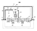
高画質化回路15の構成例を示すブロック図を図2に示す。RGB-YUV変換部151は、CPU7からビデオI/F14を介して入力されたRGB形式のビデオ信号を輝度信号と色差信号に変換し、輝度信号をY、色差信号をR-Y,及び、B-Yとして出力する。
A block diagram showing a configuration example of the image
上記RGB形式のビデオ信号をYUV信号に変換は下記式にて行うことができる。 The RGB video signal can be converted into a YUV signal by the following equation.
Y=0.290×R+0.5870×G+0.1140×B ・・・(1)
Cb=(-0.1687)×R+(-0.3313)×G+0.5000×B ・・・(2)
Cr=0.5000×R+(-0.4187)×G+(-0.0813)×B ・・・(3)
色差-HS変換部153は、RGB-YUV変換部151から入力された色差信号R-Y及び、B-Yに色相、彩度変換を施し、色相Hと彩度Sを出力する。特徴点検出部154は、RGB-YUV変換部151から入力された輝度信号Yと色差-HS変換部153から入力された色相S及び彩度Hから入力されたビデオ信号の最小レベル、平均レベル、最大レベル、ヒストグラム等の特徴点データを算出し、I/F部155に書き込む。I/F部155は所定のタイミングでCPU7に割り込み信号141を発行する。CPU7は、割り込み信号141を検出すると、内部バス1551を介してI/F部155に格納された特徴点データを読み出しし、所定のアルゴリズムによって補正データを決定し、内部バス1551を介してI/F部155に書き込む。変調部152は、入力された輝度信号Y,色相S及び彩度HにI/F部155にCPU7からライトされた補正データに従って変調を施し、輝度Y‘,色相S’及び彩度H‘として出力する。HS-色差変換部156は、入力された色相S’信号及び彩度H信号を色差信号(R-Y)'及び(B-Y)'に変換して出力する。YUV-RGB変換部157はであり、入力された輝度Y‘及び色差信号(R-Y)'及び(B-Y)'をRGB形式に変換して出力する。上記YUV-RGB変換は下式で行うことができる。
Y = 0.290 × R + 0.5870 × G + 0.1140 × B (1)
Cb = (-0.1687) × R + (-0.3313) × G + 0.5000 × B (2)
Cr = 0.5000 x R + (-0.4187) x G + (-0.0813) x B (3)
The color difference-
R=Y+1.402×V ・・・(4)
G=Y+(-0.34414)×U+(-0.71414)×V ・・・(5)
B=Y+1.772×U ・・・(6)
セレクタ158は、YUV-RGB変換部157の出力またはビデオI/F14のスルー信号142を選択して表示装置16に出力する。セレクタ158の制御はCPUから行っても良いし、バッテリー残量がある一定値以下になったときや、開閉式の携帯電話の場合は開閉に動させて切り換えても良い。また、開閉に連動させる場合、折り畳み形状の場合は開いた時にYUV-RGB変換部157側を選択した方が良いし、スライドや回転、さらに、折り畳形状であっても折り畳み方向の回転軸に加え、表示装置を180°回転させる方向の第2の軸を備えた2軸ヒンジ形式の携帯電話等、閉じた状態で表示装置を観視可能な形状の場合は閉じた時にセレクタ158においてYUV-RGB変換部157側を選択しても良い。また、TV視聴時、静止画、動画閲覧時はセレクタ158においてYUV-RGB変換部157側を選択するなど、表示させるコンテンツに応じて切り換えても良い。また、携帯電話の形状や開閉状態に関係なく、待ち受け状態ではスルー信号142を選択するようにしても良い。なお、コンテンツとは、例えば、ドラマや映画、スポーツなどの映像情報のことである。
R = Y + 1.402 × V (4)
G = Y + (-0.34414) × U + (-0.71414) × V (5)
B = Y + 1.772 × U (6)
The
なお、メール本文や字幕等のテキストデータが入力された場合は高画質化回路15におけるRGB-YUV変換を始めとする処理が不要なため、CPU7はスルー信号142を選択するように制御する。この場合、点線159で囲われた部分の動作を停止する。これにより、低消費電力化を図ることができる。具体的には高画質化回路15への動作クロック供給を停止したり、点線159内部のブロックへの電源供給を停止したりする。なお、電源供給を停止する場合、電源回路19の出力を停止しても良いし、高画質化回路15側で電源吸入経路を切断するスイッチを設けることにより電源供給を停止しても良い。
Note that when text data such as a mail text or subtitles is input, processing such as RGB-YUV conversion in the image
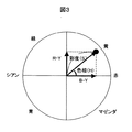
次に、色差-HS変換部153の動作の概要を図を用いて説明する。図3は、色相(H)と彩度(S)の関係を説明するための特性図である。横軸はB-Y信号のレベルを表し、縦軸はR-Y信号のレベルを表す。B-Y信号とR-Y信号のベクトル和が色相・彩度を表すベクトルで、角度が色相H、大きさが彩度Sである。よって、色相Hは(7)式で、彩度Sは(8)式で求めることができる。
Next, an outline of the operation of the color difference-
H=tan-1((R=Y)/(B-Y))・・・(7)
S=SQR((R-Y)2+(B-Y)2) ・・・(8)
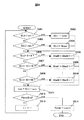
特徴点検出部154は、例えば図4に示すように、輝度特徴点検出部1541,色相特徴点検出部1542,彩度特徴点検出部1543により構成される。図5は、輝度特徴点検出部1541の検出処理の一例を示すフロー図である。輝度特徴点検出部1541は、フローに示すように、輝度特徴点検出部1541は、フレーム単位で時々刻々と入力されてくる輝度信号Yのレベル判定を行い、最大レベル、最小レベル、エリアごとレベルの頻度、平均レベル等の特徴点データを取得する。図5では、輝度レベルの入力階調が0〜255であり、この入力階調を16段階の階調エリアに分割する場合の検出処理例について説明するが、検出処理をこれに限るものではない。例えば、8段階や32段階など、メモリやゲート容量等のリソースが供される範囲で自由に設定できる。なお、輝度特徴点検出部1541により実行される検出処理プログラムは、メモリ9に記憶しても良いし、輝度特徴検出部1541に設けられらメモリに記憶するようにしても良い。
H = tan-1 ((R = Y) / (BY)) (7)
S = SQR ((RY) 2+ (BY) 2) (8)
As shown in FIG. 4, for example, the feature
まず、第n画素目の輝度レベルY(n)がメモリ9に記憶された最小レベルYminより小さいか否かを比較する(S501)。なお、最小レベルYmin、最大レベルYmaxの初期値として、それぞれ255と0とがメモリ9に記憶されている。輝度レベルが現在の最小レベルより小さい場合、第n画素目の輝度レベルを最小レベルとしてメモリ9に記憶する(S502)。輝度レベルが最小レベル以上の場合、第n画素目の輝度レベルが最大レベルより大きいか比較を行う(S503)。輝度レベルが最大値よりも大きい場合、第n画素目の輝度レベルを最大値とする(S504)。輝度レベルが最大値以下の場合、第n画素目の輝度レベルが0〜15か判定を行う(S505)。輝度レベルが0〜15の場合、Yhst0の値に1を加える(S606)。Yhst0とは、0〜15の階調エリア内に含まれる輝度レベルの数を示すものである。
First, it is compared whether or not the luminance level Y (n) of the nth pixel is smaller than the minimum level Ymin stored in the memory 9 (S501). Note that 255 and 0 are stored in the
輝度レベルが0〜15ではない場合は、輝度レベルが16〜31か判定を行う(S507)。Yesの場合は、Yhst1の値に1を加える(S508)。Noの場合は、次々と他の階調エリアに含まれるか否かを判断する。 If the luminance level is not 0-15, it is determined whether the luminance level is 16-31 (S507). If Yes, 1 is added to the value of Yhst1 (S508). In the case of No, it is determined whether or not it is included in other gradation areas one after another.
輝度レベルのエリア分けを終了すると、現在の合計輝度レベルに、第n画素目の輝度レベルを加算する(S511)。S512で、1フレーム分の処理が完了したか判定し、yesの場合は合計輝度レベルを画素数nで割ることにより、平均輝度レベルを算出して処理を終了する(S514)。Noの場合はnに1を加え、S501に戻って次の画素の輝度レベルの処理を行う。 When the luminance level area division is completed, the luminance level of the nth pixel is added to the current total luminance level (S511). In S512, it is determined whether or not the processing for one frame has been completed. If yes, the average luminance level is calculated by dividing the total luminance level by the number of pixels n, and the processing ends (S514). In the case of No, 1 is added to n, and the process returns to S501 to process the luminance level of the next pixel.
図6に、輝度ヒストグラムの例を示す。横軸が輝度ヒストグラムのエリア、縦軸が頻度である。このヒストグラムを取得することにより、輝度の特徴を容易に把握することができる。例えば、単純に暗い画面なのか、または、暗い画面の中に月や星等の明るい場所が存在する画面なのかを判定することができる。 FIG. 6 shows an example of a luminance histogram. The horizontal axis is the luminance histogram area, and the vertical axis is the frequency. By acquiring this histogram, it is possible to easily grasp the characteristics of luminance. For example, it can be determined whether the screen is simply a dark screen or a screen in which a bright place such as a moon or a star exists in the dark screen.
図7は、色相特徴点検出部1542の検出処理の一例を示すフロー図である。色相特徴点検出部1542は、フローに示すように、フレーム単位で時々刻々と入力されてくる色相信号Hのレベル判定を行い、最大レベル、最小レベル、エリアごとのレベルの頻度、平均レベルを取得する。図7では、色相レベルの範囲が0〜359であり、このレベルを12段階の色相エリアに分割する場合の処理例について説明するが、検出処理をこれに限るものではない。なお、輝度特徴点検出と同様、実行される検出処理プログラムは、メモリ9に記憶しても良いし、色相特徴点検出部1542に設けられらメモリに記憶するようにしても良い。
FIG. 7 is a flowchart illustrating an example of detection processing of the hue feature
輝度レベルと同様、S701〜S710により、第n画素目の色相レベルH(n)が、色相エリアHhst0〜Hhst11のいずれに含まれるかを検出する。色相レベルのエリアが判定されると、現在の合計色相レベルに、第n画素目の色相レベルを加算し(S711)、1フレーム分の処理が完了したか判定する(S712)。処理が完了した場合(yes)は、平均色相レベルを算出して処理を終了する(S714)。Noの場合はnに1を加え(S713)、S701に戻って次の画素の色相レベルの処理を行う。 Similar to the luminance level, in S701 to S710, it is detected which of the hue areas Hhst0 to Hhst11 the hue level H (n) of the nth pixel is included. When the hue level area is determined, the hue level of the nth pixel is added to the current total hue level (S711), and it is determined whether the processing for one frame is completed (S712). When the process is completed (yes), the average hue level is calculated and the process ends (S714). If No, 1 is added to n (S713), and the process returns to S701 to process the hue level of the next pixel.
図8に、以上のようにして検出したエリア頻度を用いて作成した色相ヒストグラムの例を示す。横軸が色相ヒストグラムのエリア、縦軸が頻度である。ヒストグラムを生成することにより、色相の変化の特徴を容易に把握することができる。 FIG. 8 shows an example of a hue histogram created using the area frequency detected as described above. The horizontal axis is the hue histogram area, and the vertical axis is the frequency. By generating the histogram, it is possible to easily grasp the characteristics of the hue change.
図9は、彩度特徴点検出部1543の検出処理の一例を示すフロー図である。彩度特徴点検出部1543は、フレーム単位で時々刻々と入力されてくる彩度信号Sのレベル判定を行い、最大レベル、最小レベル、エリアごとのレベルの頻度、平均レベルを取得する。図9では、彩度レベルの範囲が0〜99であり、このレベルを10段階のエリアに分割する場合の処理例について説明するが、検出処理をこれに限るものではない。なお、輝度特徴点検出と同様、実行される検出処理プログラムは、メモリ9に記憶しても良いし、彩度特徴点検出部1543に設けられらメモリに記憶するようにしても良い。
FIG. 9 is a flowchart showing an example of detection processing of the saturation feature
輝度レベルと同様、S901〜S910により、第n画素目の彩度レベルS(n)が、色相エリアShst0〜Shst9のいずれに含まれるかを検出する。彩度レベルのエリアが判定されると、現在の合計彩度レベルに、第n画素目の彩度レベルを加算し(S911)、1フレーム分の処理が完了したか判定する(S912)。処理が完了した場合(yes)は、平均彩度レベルを算出して処理を終了する(S914)。Noの場合はnに1を加え(S913)、S901に戻って次の画素の彩度レベルの処理を行う。 Similar to the luminance level, in S901 to S910, it is detected which of the hue areas Shst0 to Shst9 includes the saturation level S (n) of the nth pixel. When the saturation level area is determined, the saturation level of the nth pixel is added to the current total saturation level (S911), and it is determined whether the processing for one frame is completed (S912). When the process is completed (yes), the average saturation level is calculated and the process is terminated (S914). If No, 1 is added to n (S913), and the process returns to S901 to process the saturation level of the next pixel.
図10に、彩度ヒストグラムの例を示す。横軸が彩度ヒストグラムのエリア、縦軸が頻度である。この色相ヒストグラムを取得することにより、入力されたビデオ信号の彩度の変化を検出することができる。 FIG. 10 shows an example of a saturation histogram. The horizontal axis is the saturation histogram area, and the vertical axis is the frequency. By obtaining this hue histogram, it is possible to detect a change in the saturation of the input video signal.
図11は、I/F部155の内部構成の一例を示すブロック図である。I/Fレジスタ部1551を介してCPU7と高画質化回路15の間で信号の書き込み、読み出しを行う。シーンチェンジ検出部1552は、特徴点検出部154から輝度レベル、色相、彩度の特徴点データが入力されると、これらデータを保存する。そして、新たなデータが入力されると、データを書き換えるとともに、新旧データの差分の有無を判定する。差分がある場合、シーンチェンジが発生したと判定し、CPU7に対してINT141を発行する。CPU7は、I/Fレジスタ1551から新しい特徴点データを読み出して新しい補正データを生成し、I/Fレジスタ1551の補正データを更新する。本例では、CPU7がI/Fレジスタ1551から特徴点データを読み出したが、I/Fレジスタ1551がCPU7にデータを送信しても良い。なお、シーンチェンジとは、例えば、番組からCM(コマーシャルメッセージ)に変わった場合や、番組中で昼のシーンから夜のシーンに変わった場合、撮影場所が変わった場合、スタジオ画像から現地画像への切換、さらに、スタジオやスタジアム内におけるTVカメラの切り換わりなどが挙げられる。
FIG. 11 is a block diagram illustrating an example of an internal configuration of the I /
図12は、シーンチェンジ検出部1552の検出処理の一例を示すフロー図である。S1201において、新旧の最小輝度レベルの差分を求めるとともに、新データをI/Fレジスタ1551に書き込む。最大輝度レベル,平均輝度レベル,エリアごとの頻度に関しても同様に差分を求める。エリア15の頻度の差分を求めると(S1202)、色相特徴点の処理に移行する。色相に関しても輝度と同様にS1203〜S1204により最小色相レベル、最大色相レベル,平均色相レベル,頻度の差分を求め、彩度特徴点の差分を求める(S1205〜S1206)。輝度、色相、彩度の特徴点の差分が“0”即ち、前のフレームと同一であったか判定し(S1207)、差分がない場合は補正データの更新は必要ないと判断し、処理を終了する。一方、noの場合は、シーンチェンジが発生したと判断し、CPU7に対して割り込み要求141を出力し(S1208)、処理を終了する。
FIG. 12 is a flowchart showing an example of the detection process of the scene
上記説明したようにシーンチェンジ検出部1552が動作することにより、前のフレームと同じ絵柄の場合は、CPU7による特徴点データの読み出し、補正データの生成、I/Fレジスタ1551への書き込み処理を省略できるため、CPU7の処理負荷低減するとともに、データ転送のための消費電流を低減することができる。
As described above, when the scene
なお、図12には、輝度、色相、彩度のすべての差分を検出する例を示したが、これに限定するものではない。また、最小値、最大値等のすべての特徴点について差分を検出しなくても良い。CPU7での処理負荷を低減するためには、ユーザーの視覚への影響が大きい輝度信号の平均レベルの差分の有無に基づいて、シーンチェンジを検出するのが最も有効である。また、例えば輝度の最小値と最大値の両方が変化したとき、輝度の最小値と色相の平均値等のように各特徴点データの組み合わせで判定しても良い。ヒストグラムの分布エリア(横軸)が変化した場合にシーンチェンジと判定しても良い。
Although FIG. 12 shows an example in which all differences in luminance, hue, and saturation are detected, the present invention is not limited to this. Further, it is not necessary to detect the difference for all feature points such as the minimum value and the maximum value. In order to reduce the processing load on the
また、図12の例では、特徴点データの差分が0である場合にシーンチェンジ無しと判定したが、ある一定の閾値を設け、それを超えた時にシーンチェンジと判定しても良い。この閾値は、各特徴点データで個別に設定することが望ましい。また、字幕の有無による補正データの更新を防ぐため、例えば白側のヒストグラムの頻度が変化してもシーンチェンジと判定しない等、特定の階調エリアや頻度のエリアを無視するようにしても良い。なお、輝度レベル等を用いてシーンチェンジを検出した場合に追加して、シーンチェンジ検出部1552は、一定の時間またはフレーム数ごとにシーンチェンジと判定し、INT141を出力するようにしても良い。
In the example of FIG. 12, it is determined that there is no scene change when the difference between the feature point data is 0. However, a scene change may be determined when a certain threshold value is set and exceeded. This threshold is preferably set individually for each feature point data. Also, in order to prevent the correction data from being updated due to the presence or absence of captions, a specific gradation area or frequency area may be ignored, for example, it is not determined as a scene change even if the frequency of the histogram on the white side changes. . In addition, when a scene change is detected using a luminance level or the like, the scene
CPU7により生成された補正データに基づいて、変調部152により、輝度、色相、彩度の変調を行う。以下、変調方法について説明を行う。
Based on the correction data generated by the
図13に、変調部152において輝度信号を変調する場合の処理フローの例を示す。まず、輝度ヒストグラムの第1階調エリア(Yhst0)が0か否かの判定を行う(S1301)。Noの場合、Blacklevelを0にする(S1302)。ここで、Blacklevel とは、出力階調を0に固定する入力階調の範囲を示すものであり、Blacklevelを0にするとは、出力階調を0にする範囲がない状態である。Yesの場合、輝度ヒストグラムの第2階調エリア(Yhst1)が0か否かの判定を行う(S1303)。Noの場合、Blacklevelを0〜15とす(S1304)る。Yesの場合、輝度ヒストグラムの第3階調エリア(Yhst2)が0か判定を行う(S1305)。Noの場合、Blacklevelを0〜31とする(S1306)。Yesの場合、第4階調エリア(Yhst3)移行の判定は行わず、Blacklevelを0〜47とする。このように限界値を設けることにより、輝度が過度に補正されるのを防ぐことができる。
FIG. 13 shows an example of a processing flow when the
次に、輝度ヒストグラムの第16階調エリア(Yhst15)が0か判定を行う(S1308)。Noの場合、Whitelevelを255とする(S1309)。ここで、Whitelevelとは、出力階調を255に固定する入力階調の範囲を示すものであり、Whitelevelを255とするとは、出力階調を255にする範囲がない状態である。Yesの場合、輝度ヒストグラムの第15階調エリア(Yhst14)が0か判定を行う(S1310)。Noの場合、Whitelevelを239〜255とする(S1311)。Yesの場合、輝度ヒストグラムの第14階調エリア(Yhst13)が0か判定を行う(S1312)。Noの場合、Whitelevelを223〜255とする(S1313)。Yesの場合、輝度ヒストグラムの第13階調エリア(Yhst12)の判定は行わず、Whitelevelを207〜255とする(S1314)。このように白側の限界値を設けることにより、過補正を防ぐことができる。 Next, it is determined whether the 16th gradation area (Yhst15) of the luminance histogram is 0 (S1308). In the case of No, Whitelevel is set to 255 (S1309). Here, Whitelevel indicates an input gradation range in which the output gradation is fixed to 255, and Whitelevel is 255 when there is no range in which the output gradation is 255. If Yes, it is determined whether the 15th gradation area (Yhst14) of the luminance histogram is 0 (S1310). In the case of No, Whitelevel is set to 239 to 255 (S1311). If Yes, it is determined whether the 14th gradation area (Yhst13) of the luminance histogram is 0 (S1312). In the case of No, Whitelevel is set to 223 to 255 (S1313). If Yes, the 13th gradation area (Yhst12) of the luminance histogram is not determined, and Whitelevel is set to 207 to 255 (S1314). By providing the white side limit value in this way, overcorrection can be prevented.
出力階調を0または255に固定する範囲が決まると、黒側及び、白側の階調を0または255に固定した階調分(潰した分)を除いた入力階調に出力可能な0〜255までの階調を使用するように伸張処理を行う(S1501)。これにより、入力階調に対する出力階調の傾き(Ygain)を大きくするように補正することができる。 When the range in which the output gradation is fixed to 0 or 255 is determined, 0 can be output to the input gradation excluding the gradation in which the gradation on the black side and the white side is fixed to 0 or 255 (crushed portion). The expansion processing is performed so as to use the gradations up to ˜255 (S1501). As a result, it is possible to perform correction so as to increase the gradient (Ygain) of the output gradation with respect to the input gradation.
図14〜図16を用いて、変調部152における輝度信号の変調方法例を説明する。
An example of a luminance signal modulation method in the
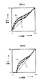
図14(a)は、輝度ヒストグラムである。この例では、黒側である0〜47(Yhst0〜2)までの階調が存在しない。即ち、黒が少なく、白っぽい(黒レベルが浮き気味の)ビデオ信号が入力された場合の例である。図13の処理フローに当てはめると、Blacklevel=0〜47,Whitelevel=255となり、伸長処理されることにより、傾きYgain=1.22に補正される。入力階調に対する出力階調の関係を補正したものを補正特性という。
FIG. 14A is a luminance histogram. In this example, there are no gradations from 0 to 47 (
図14(b)に、この補正特性による補正イメージを示す。点線1401は、補正をしない場合の入力階調に対する出力階調の特性を示したものである。実線1402が補正特性である。入力ビデオ信号の階調が存在しない0〜47を0に固定した分、入力階調47〜255に対する出力階調の傾きが大きくなっている。これにより、入力階層に対する出力階層のコントラストを大きく、視聴しやすい画像を表示することができる。
FIG. 14B shows a correction image based on this correction characteristic. A dotted
図15は白側に階調が存在しないビデオ信号が入力された場合の補正例を示す図である。図15(a)は、入力されたビデオ信号の輝度ヒストグラムである。白側である207〜255(Yhst13〜15)までの階調が存在しない、即ち、黒っぽい映像のビデオ信号が入力された場合の例である。図13の処理フローに当てはめると、Blacklevel=0,Whitelevel=207〜255,Ygain=1.22となる。
FIG. 15 is a diagram illustrating an example of correction when a video signal having no gradation on the white side is input. FIG. 15A is a luminance histogram of the input video signal. This is an example of the case where there are no gray levels from 207 to 255 (
この補正特性による補正のイメージを図15(b)に示す。点線1501は、補正をしない場合の入力階調に対する出力階調の特性を示したものである。実線1502が補正特性である。入力ビデオ信号の階調が存在しない207〜255の出力階層を255に固定した分、入力階調0〜207に対する出力階調の傾きを大きくし、出力ダイナミックレンジ限界の0まで伸張する。このような補正特性とすることにより、入力階層に対する出力階層のコントラストを大きくなり、黒側の階調が見やすい画像を表示することができる。
An image of correction by this correction characteristic is shown in FIG. A dotted
図16は、黒側と白側に階調が存在しないビデオ信号が入力された場合の補正例である。図16(a)は入力されたビデオ信号の輝度ヒストグラムである。この例では、黒側である0〜31(Yhst0〜1),白側である223〜255(Yhst14〜15)までの階調が存在しない。図13の処理フローに当てはめると、Blacklevel=0〜31,Whitelevel=223〜255,Ygain=1.33となる。
FIG. 16 shows an example of correction when a video signal having no gradation on the black side and the white side is input. FIG. 16A is a luminance histogram of the input video signal. In this example, there are no gradations from 0 to 31 (
この補正特性による補正のイメージを図16(b)に示す。点線1601は、補正をしない場合の入力階調に対する出力階調の特性を示したものである。実線1602が補正特性である。入力ビデオ信号の階調が存在しない0〜31と223〜255の出力階層をそれそれ0と255に固定した分、入力階調31〜223に対する出力階調の傾きを大きくし、出力ダイナミックレンジ限界の0から255まで伸張するものである。このように補正することにより、中間階層のコントラストが大きく、視聴しやすい画像を表示することができる。
An image of correction by this correction characteristic is shown in FIG. A dotted
図17に、色相補正のフロー例を示す。本実施例では、ユーザーが予め、黄、赤、マゼンダ、青、シアン、緑等の色の中から、特に鮮やかにしたい、強調したい色を選択しておく。そして、ユーザーの選択された色および色相ヒストグラムのピークエリアHhst maxにより、色補正を行う。図17は、例えば、青が選択されている場合の補正処理を示す。まず、色相ヒストグラムのピークHhst maxが、青に該当するエリアH hst9の前のエリアであるH hst8に該当するか判定を行う(S1701)。判定の結果がyesの場合は、色相調整値Hadjを10とする(S1702)。Noの場合、色相ヒストグラムのピークエリアHhst maxが、青に該当するエリアH hst9の後ろのエリアであるH hst10に該当するか判定を行う(S1703)。判定の結果がyesの場合は、色相調整値Hadjを−10とする(S1704)。Noの場合、Hadjを0とし、処理を終了する。これにより、ユーザーが設定した色を強調することができる。 FIG. 17 shows a flow example of hue correction. In this embodiment, the user selects in advance a color to be particularly vivid or emphasized from among colors such as yellow, red, magenta, blue, cyan, and green. Then, color correction is performed based on the color selected by the user and the peak area Hhst max of the hue histogram. FIG. 17 shows a correction process when, for example, blue is selected. First, it is determined whether the peak Hhst max of the hue histogram corresponds to H hst8 that is the area before the area H hst9 corresponding to blue (S1701). If the determination result is yes, the hue adjustment value Hadj is set to 10 (S1702). In the case of No, it is determined whether the peak area Hhst max of the hue histogram corresponds to H hst10 that is an area after the area H hst9 corresponding to blue (S1703). If the determination result is yes, the hue adjustment value Hadj is set to −10 (S1704). If No, Hadj is set to 0 and the process is terminated. Thereby, the color set by the user can be emphasized.
図17の例では、ユーザーが事前に設定した色に基づいて補正を行ったが、これに限定するものではない。例えば、色相ヒストグラムのピークエリアを検出し、ピークエリアの前後のエリアの色をピークエリアの色に補正するようにしても良い。これにより、浜辺の映像の場合など、青色近辺の成分が多い場合には色相を青側に調節して、青を強調した映像を表示することができる。 In the example of FIG. 17, the correction is performed based on the color set in advance by the user, but the present invention is not limited to this. For example, the peak area of the hue histogram may be detected, and the color of the area before and after the peak area may be corrected to the color of the peak area. Thereby, when there are many components near blue, such as in the case of a beach image, the hue can be adjusted to the blue side to display an image in which blue is emphasized.
図18に、彩度補正のフロー例を示す。彩度の最大レベルが80以下であるか判定し(S1801)、noの場合は彩度のゲインSgainを1.2とする(S1802)。Yesの場合、Sgainを1.0とし(S1803)、終了する。これにより、最大彩度がある一定値以下の場合は彩度ゲインを強調してより色鮮やかな表示を行うことができる。なお、図18の例では、最大彩度が一定値以下の場合に補正を行ったが、これに限定するものではない。最大彩度がある一定値以上の場合に、色潰れの発生を避けるため、ゲインを低下させても良い。 FIG. 18 shows a flow example of saturation correction. It is determined whether the maximum level of saturation is 80 or less (S1801). If no, the saturation gain Sgain is set to 1.2 (S1802). If Yes, Sgain is set to 1.0 (S1803), and the process ends. Thereby, when the maximum saturation is equal to or smaller than a certain value, the saturation gain can be emphasized and more vivid display can be performed. In the example of FIG. 18, the correction is performed when the maximum saturation is equal to or less than a certain value, but the present invention is not limited to this. When the maximum saturation is equal to or greater than a certain value, the gain may be reduced in order to avoid color collapse.
以上説明したようにシーンチェンジを検出し、信号変調を行うことにより、消費電力を抑えつつ、コントラストのはっきりした良好な画像を視聴することができる。 As described above, by detecting a scene change and performing signal modulation, it is possible to view a good image with clear contrast while suppressing power consumption.
変調部152が入力映像信号に変調を施すタイミングは、CPU7からの指示の直後でも良いし、一定の時間またはフレーム経過後でも良い。また、徐々に目的の補正特性に収束させるよう過渡的に行っても良い。また、CPU7が復号前の画像ファイルのヘッダー情報により圧縮率が高いと判断した場合や、TVチューナー13から取得したビットエラーレート等により受信状態が良くないと判断した場合には、ブロックノイズが発生する可能性が高いため、補正の程度を弱くし、ブロックノイズが強調されるのを防ぐようにしても良い。また、逆に圧縮率が低いと判断した場合にはブロックノイズが発生する可能性が低いため、補正の程度を強くして、より高画質な表示を行うようにしても良い。例えば、圧縮率が高い場合、Blacklevelの限界値を23に変更したり、色相調整値Hadjを5に変更したり、彩度ゲインSgainを1.1に変更して、補正の程度を弱くする。
The timing at which the
また、本実施例では上述の高画質化処理を高画質化回路15で実現する場合の例について説明したが、CPU7の処理能力に余裕があれば高画質化回路15を使用せず、高画質化の一部または全ての処理をCPU7でソフト的に行っても良い。
In this embodiment, an example in which the above-described image quality improvement processing is realized by the image
また、本実施例ではI/F部155内にシーンチェンジ検出部1552を設け、そのブロックからのINT141によってCPU7が補正データの生成、更新処理を行う場合の例について述べたが、符号化された画像を復号した際にIピクチャーやIDR(Instantaneous Decoding Refresh)ピクチャー等の特定のピクチャーを生成したときに行っても良い。
In this embodiment, the scene
図19は、携帯電話の別の構成例を示すブロック図である。図1と同一部分には同一符号を付し、説明は省略する。携帯電話は屋内や屋外の様々な場所で使用されるため、使用状況に応じて周囲の照度が異なる。晴れた日の屋外等、明るい環境では、周囲の光が表示装置16に入射し、表示画像の低輝度側、即ち、黒側の階調が識別し難くなるという問題がある。図19に示す携帯電話は、照度センサ21を有し、入力信号の特徴点による補正に加え、照度による補正データを重畳する。
FIG. 19 is a block diagram illustrating another configuration example of the mobile phone. The same parts as those in FIG. Since mobile phones are used indoors and outdoors, the ambient illuminance varies depending on the usage situation. In a bright environment such as outdoors on a sunny day, ambient light is incident on the
照度センサ21は、フォトトランジスタやフォトダイオード等により構成される。照度センサ21の出力特性の一例を図20に示す。横軸は環境照度、縦軸は照度センサの出力レベルであり、環境照度が大きくなるに従って照度センサ21の出力レベルも大きくなるものとする。なお、本例では、照度を検出する手段として、照度センサ7を設けたが、CMOSやCCDのカメラの出力信号を使用して照度を検出するようにしても良い。
The
メモリ9には、照度センサ21により検出された照度が所定値以上になった場合に出力階調を補正する補正データを記憶する。図21に、補正データの一例を示す。階調エリアYhstごとの補正値を設定している。本例では、黒側の階調を識別しやすくするように、黒側の出力階層を補正するようにしている。なお、本例では、照度が所定以上の場合の補正データを1種類設けているが、照度に応じて、補正値の大きさや補正する階調範囲を変更した複数種類の補正データを設けるようにしても良い。これら複数種類の補正データは、メモリ9に記憶しても良いし、例えば図21に示した補正データを基準データとし、これに照度に応じた係数を乗算することにより算出するようにしても良い。
The
図22に、高画質化回路15の内部ブロック図を示す。図2に示す高画質化回路に、RGBゲイン調整部1510を追加したものである。図2と同一部分には同一符号を付し、説明は省略する。
FIG. 22 shows an internal block diagram of the image
照度センサ7により検出された照度はCPU7に入力される。照度が所定以上の場合、CPU7はRGBゲイン調整部1510へ出力階調の補正を指示する制御信号を出力する。RGBゲイン調整部1510は、CPU7からの制御に応じて、I/F部155を通じて補正データをメモリ9から読み出し、ビデオ信号のゲインを調節する。以下、RGBゲイン調整部1510による照度による補正データの重畳動作を図23を用いて説明する。
The illuminance detected by the
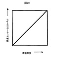
図23(a)は、Blacklevel=0、Whitelevel=255であり、変調部152で補正されなかった場合の輝度信号の入力階調に対する出力階調の特性を示したものである。照度が所定値以上の場合、図23(b)に示すように、入力階調に対する出力階調を補正する。具体的には、RGBゲイン調整部1510により、黒側の出力階調を強調するように補正が施され、明るい環境でも、視聴しやすい画像を表示することができる。一方、照度が所定値未満の場合、RGBゲイン調整部1510は補正を行わず、入力階調に対する出力階調は、図23(a)のままである。
FIG. 23A shows the characteristics of the output gradation with respect to the input gradation of the luminance signal when Blacklevel = 0 and Whitelevel = 255 and are not corrected by the
図23(c)は、Blacklevel=0〜47、Whitelevel=255であり、変調部152により、入力階調47〜255に対する出力階調が補正された状態を示している。照度が所定値以上の場合、図23(d)に示すように、RGBゲイン調整部1510は、メモリ9から読み出した補正データを用いて、入力階調に対する出力階調を補正する。本例では、Blacklevel=0〜47の範囲については、RGBゲイン調整部1510により補正を行わないように制御しているが、RGBゲイン調整部1510での補正量が一定以下の場合には、ゲイン変調を施してもさほど問題はない。
FIG. 23C shows a state in which Blacklevel = 0 to 47 and Whitelevel = 255, and the output gradation for the input gradations 47 to 255 is corrected by the
なお、以上の例では、照度に応じて、黒側の階調を強調したが、これに限定するものではなく、周囲の光の色に応じて補正を行うようにしても良い。例えば、外光の色が夕日などの赤みがかった光の場合には、外光の影響により、表示画像の色も赤みがかってしまうという問題がある。 In the above example, the gradation on the black side is emphasized according to the illuminance. However, the present invention is not limited to this, and the correction may be performed according to the color of ambient light. For example, when the color of the external light is reddish light such as sunset, there is a problem that the color of the display image is reddish due to the influence of the external light.
この問題を解消するために、照度センサ21がRGB(Red-Green-Blue)独立した3系統の検出素子を有し、それら検出素子の比率をCPU7で計算する。これにより、外光の強さに加えて色によって、変調を行う。
In order to solve this problem, the
CPU7は、照度センサ21のRGB各出力色の比率を計算し、RGBいずれかの成分が多い場合には、RGBゲイン調整部1510に対し、成分が多い色については補正値を下げるように制御する。例えば、周囲の光が夕日や白熱灯の場合など、周囲の光にR成分が多いことを検出すると、RGBゲイン調整部1510に対し、G,Bに対してRの補正データが少なくなるように指示する。
The
図24(a)は、変調部152で輝度信号の入力階調に対する出力階調が補正されなかった場合に、RGBゲイン調整部1510により補正した状態を示したものである。また、図24(b)は、変調部152により、入力階調47〜255に対する出力階調が補正された場合に、RGBゲイン調整部1510により補正した状態を示したものである。それそれ、G,Bに対してRのゲインを下げるように補正している。これにより、表示装置16上でのRGBの比率を所望の比率に保ち、良好な表示を行うことができる。ここでは外光にR成分が多い場合の例について説明したが、外光にGあるいはBが多い場合も、同様に補正することができる。
FIG. 24A shows a state in which the RGB
また、入力信号の変調に加えて、周囲の光の色に応じて。バックライト17の色を変調するようにしても良い。
Also according to the color of the ambient light in addition to the modulation of the input signal. The color of the
バックライト17及びバックライト駆動回路18の構成例を図25に示す。光源素子(LED)171〜173は、それぞれR-LED、G-LED、B-LEDである。電流制御手段183〜185は、制御回路181の指示に基きそれぞれLED171〜LED173の電流を個別に制御する。DC-DCコンバータ182は、LED171〜173を駆動するように、バッテリー20から供給された電圧を昇圧または降圧する。制御回路181は、CPU7の指示により、電流制御手段183〜185の電流値を設定する。一般にLED171〜LED173の光度は、アノード−カソード間を流れる電流に比例するため、CPU7から制御回路181及び調整手段183〜185を介してLED171〜LED173の電流を制御する光度を個別に制御できる。
A configuration example of the
図26に、周囲の光にRの成分が多い場合のLED171〜LED173の制御例を示す。縦軸は、LED171〜LED173に流す電流を示している。R成分が多い場合、R-LED171の電流をLED172及びLED173に対して少なくするように制御する。このように制御することにより、周囲の光の色によって表示画像の色が変化してしまうことを防止することができる。
FIG. 26 shows a control example of the
外光にR成分が多い場合の例について説明したが、外光にGが多い場合は緑色LED172の電流をR、Bのそれに比べて少なくすれば良く、外光にBが多い場合はB-LED173の電流をR、Gのそれに比べて少なくすれば良い。
The case where there is a lot of R component in the outside light has been explained. However, if there is a lot of G in the outside light, the current of the
なお、本例では、光源素子としてR-LED171、G-LED172、B-LED173を各1個づつ使用する場合について説明したが、これに限られるものでなく、微小なLEDを各色複数系統配置したLEDアレイ型のバックライトや有機ELディスプレイのような自発光型のディスプレイを光源として使用した場合に本制御方法を適用しても良い。
In this example, the case where one R-
以上、バックライト17によって外光の色に対する補正を行う場合の例について説明したが、外光照度が高い場合にはLED171〜LED173の電流を同じ割合で増加させることによって良好な画像観視が可能である。また、逆に外光照度が低い場合にはLED171〜LED173の電流を同じ割合で減少させることにより低消費電力化が可能である。
As described above, the example in the case of correcting the color of the external light by the
以上、携帯電話等の携帯端末装置を例にして説明してきたが、本発明の適用は、携帯端末装置に限られない。映像を視聴可能な映像処理装置であれば、いかなる装置に適用しても良い。例えば、通信機能を有していない端末装置であっても構わない。また、高画質表示の低消費電力化が可能なことからバッテリーで動作する携帯端末に特に有効であるが、家庭用コンセントからの給電で動作する据え置き型の端末装置であっても構わない。 As described above, the mobile terminal device such as a mobile phone has been described as an example, but the application of the present invention is not limited to the mobile terminal device. Any video processing apparatus capable of viewing video may be used. For example, a terminal device that does not have a communication function may be used. In addition, since it is possible to reduce power consumption for high-quality display, it is particularly effective for a portable terminal that operates with a battery. However, a stationary terminal apparatus that operates with power supply from a household outlet may be used.
放送局において、例えば縦横比4:3のコンテンツを縦横比16:9の横長映像信号に変換する際、コンテンツの左右に模様が付けられた壁紙エリアや単一色の無画エリアなどのパターン部分を付加することがある。パターン部分は、映像を見やすくするために、固定であることが好ましいが、マーク等の一部分が変化するものであっても良い。 In a broadcasting station, for example, when converting content with an aspect ratio of 4: 3 into a horizontally long video signal with an aspect ratio of 16: 9, a pattern portion such as a wallpaper area or a single-color non-image area with patterns on the left and right sides of the content is displayed. May be added. The pattern portion is preferably fixed in order to make the image easy to see, but a part of the mark or the like may be changed.
パターン部分が付加された映像信号をフレーム単位あるいはシーン単位に画質補正を施すと、映像信号内容に応じてパターン部分の輝度や色が変化するため、かえって見苦しくなる可能性がある。本実施例では、パターン部分の有無を検出する検出部を設け、パターン部分を検出した場合には画質補正を停止する機能を備えた携帯電話の例について述べる。 When image quality correction is performed on a video signal with a pattern portion added in units of frames or scenes, the luminance and color of the pattern portion change according to the content of the video signal, which may be unsightly. In the present embodiment, an example of a mobile phone provided with a detection unit for detecting the presence or absence of a pattern portion and having a function of stopping image quality correction when a pattern portion is detected will be described.
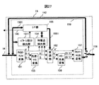
図27は、携帯電話の高画質化回路の他の構成例を示すブロック図である。図2に示す高画質化回路に、画像左右に挿入されたパターン部分を検出するパターン部分検出部1511を追加したものである。図2と同一部分には同一符号を付し、説明は省略する。
FIG. 27 is a block diagram illustrating another configuration example of the image quality improving circuit of the mobile phone. A
パターン部分検出部1511の構成例を図28に示す。水平位置カウンタ15111は、入力映像信号のドットクロックをカウントし、所定の値になった時点で水平イネーブル信号を出力する。また、水平位置カウンタ15111は、表示装置16の水平方向の画素数と一致した時点で水平パルスを出力し、カウント値をクリアする。垂直位置カウンタ15112は、水平位置カウンタ15111から出力された水平パルスをカウントし、所定の値になった時点で垂直イネーブル信号を出力する。また、垂直位置カウンタ15112は、表示装置16の垂直方向の画素数と一致した時点で垂直パルスを出力し、カウント値をクリアする。
A configuration example of the pattern
アンドゲート15113は、水平位置カウンタ15111から出力された水平イネーブル信号と垂直位置カウンタ15112から出力された垂直イネーブル信号の論理積を出力する。ラッチ回路15114は、アンドゲート15113の出力に基いてRGB−YUV変換部151から出力された輝度信号Yの値を取り込んで保持する。
The AND
図29は、表示装置16におけるパターン部分検出ポイントの位置を示している。表示装置16の画素数は、例えば水平320dot,垂直180dot、縦横比が16:9とする。この表示装置16に縦横比4:3のコンテンツの左右にパターン部分を挿入した画像を表示させる場合、4:3コンテンツの垂直方向を表示装置16の画素数に一致させて180dotとすると、水平方向画素数は240dotとなるため、左右に40dotずつパターン部分が表示されることになる。検出ポイントは、このパターン部分表示エリア内に設けたP11,P12,P13の3箇所と、コンテンツ表示エリア内に設けたP21,P22,P23の3箇所、合計6箇所配置する。
FIG. 29 shows the position of the pattern portion detection point on the
各検出ポイントの座標は表示装置16の左上を原点A(x、y)=(0,0)とすると、P11は(20,20),P21は(60,20),P12は(20,90),P22は(60,90),P13は(20,160),P23は(60,160)とする。本実施例では、パターン部分は映像の左右に均等に挿入されるものとして左側だけで検出する場合の例について説明しているが、これに限られるものではなく、右側だけで検出しても良いし、左右両方で検出しても良い。また、シネマスコープサイズ等の16:9よりもさらに横長のコンテンツを表示する場合は、コンテンツ表示エリアの上下にパターン部分が挿入されている可能性があるため、画像上下に検出ポイントを設けても良い。また、検出ポイントの数についても最低限、コンテンツ表示エリア以外に1個以上あれば良い。あるいは、フレームメモリのように表示装置16の画素数またはコンテンツの画素数分設けても良い。
As for the coordinates of each detection point, assuming that the upper left of the
次に、水平位置カウンタ15111の動作例を図30を用いて説明する。水平位置カウンタ15111は、例えば、水平イネーブル信号を生成するため検出ポイントのx座標である20,60と、表示装置16の水平方向画素数である320をプリセットする。プリセットはCPU7から行っても良いし、水平位置カウンタ15111内部で固定しても良い。このように水平位置カウンタ15111に初期値をプリセットすることにより、水平位置カウンタ15111は入力されたドットクロックをカウントし、プリセットされた20及び、60クロック目がHighレベルとなる水平イネーブル信号を出力する。また、320クロック目がHighレベルとなる水平パルスを出力する。尚、水平位置カウンタ15111は、水平パルスを出力した時点でカウント値をリセットして、再び“0”からカウントを再開し、周期的に上述のタイミングで水平イネーブル信号及び、水平パルス出力を出力する動作を繰り返す。
Next, an operation example of the
垂直位置カウンタ15112の動作例を図31を用いて説明する。垂直位置カウンタ15112は、例えば、垂直イネーブル信号を生成するため検出ポイントのy座標である20,90,160と、表示装置16の垂直方向画素数である180をプリセットする。プリセットはCPU7から行っても良いし、垂直位置カウンタ15112内部で固定しても良い。このように垂直位置カウンタ15112に初期値をプリセットすることにより、垂直位置カウンタ15112は水平位置カウンタ15111から出力される水平パルスをカウントし、プリセットされた20,90及び、160カウント目でHighレベルとなる垂直イネーブル信号を出力する。また、180カウント目でHighレベルとなる垂直パルスを出力する。尚、垂直位置カウンタ15112は垂直パルスを出力した時点でカウント値をリセットして再び“0”からカウントを再開し、周期的に上述のタイミングで垂直イネーブル信号及び、垂直パルス出力する動作を繰り返す。
An operation example of the
アンドゲート15113の入出力波形の一例を図32に示す。同図は、垂直位置カウンタ15112のカウント値が20になっている場合の例を示している。アンドゲート15113は、水平イネーブル信号及び垂直イネーブル信号が共にHighレベルの時のみ、Highレベルを出力する。よって、アンドゲート15113の出力は、垂直位置カウンタ15112の20,90,160カウント目の水平位置カウンタ15111の20及び、60クロック目がHighレベルとなる。
An example of input / output waveforms of the AND
ラッチ回路15114は、アンドゲート15113がHighレベルのタイミングで輝度信号Yの値を取り込んで1フレーム分保持することにより、各検出ポイントの輝度信号Yの値を取得することができる。
The
次に、I/F部155におけるパターン部分の判定フローを図33を用いて説明する。垂直パルスを受信したか判定し(S3301)、受信していない場合は垂直パルスの受信待ちを行い、受信した場合はS3302に移行する。パターン部分検出部1511から各検出ポイントの輝度信号Yの値を取得し(S3302)、各検出ポイントにおける前フレームとの差分を求める(S3303)。
Next, a pattern portion determination flow in the I /
4:3映像を表示した場合にパターン部分表示領域になる検出ポイントであるP11,P12,P13について、前フレームとの差分が“0”かどうかを判定する(S3304)。この差分が“0”でないときは、パターン部分が含まれていないと判断し、S3308に移行する。 It is determined whether or not the difference from the previous frame is “0” for P11, P12, and P13, which are detection points that become the pattern partial display area when 4: 3 video is displayed (S3304). If this difference is not “0”, it is determined that the pattern portion is not included, and the process proceeds to S3308.
一方、差分が“0”の場合は、パターン部分が含まれている可能性があると判断し、S3305に移行する。P11,P12,P13の差分が“0”の場合であっても、中心部しか動きがないコンテンツである可能性がある。S3305では、このようなコンテンツを識別するために、4:3映像を表示した場合にコンテンツ表示領域になる検出ポイントであるP21,P22,P23について、前フレームとの差分が“0”か判定する。この差分が“0”の時は、中心部しか動いていないようなコンテンツであると判断し、S3308に移行する。 On the other hand, if the difference is “0”, it is determined that the pattern portion may be included, and the process proceeds to S3305. Even if the difference between P11, P12, and P13 is “0”, there is a possibility that the content has movement only at the center. In S3305, in order to identify such content, it is determined whether the difference from the previous frame is “0” for P21, P22, and P23 that are detection points that become the content display area when 4: 3 video is displayed. . When the difference is “0”, it is determined that the content is moving only in the center, and the process proceeds to S3308.
P21,P22,P23におけるフレーム差分が“0”でないときは、パターン部分が含まれていると判断し、レジスタの一部に設けているパターン部分の有無を示すフラグを“1”:「パターン部分有り」に設定する(S3306)。そして、CPU7に対して割り込みを発行し、レジスタのリードを要求し、パターン部分付きコンテンツであることをCPU7に通知する(S3307)。S3308では、各検出ポイントの輝度信号Yの値を保存し、前フレームデータとする。
When the frame difference in P21, P22, and P23 is not “0”, it is determined that the pattern portion is included, and a flag indicating the presence / absence of the pattern portion provided in a part of the register is set to “1”: “pattern portion”. It is set to “present” (S3306). Then, an interrupt is issued to the
図34にCPU7での処理フローを示す。CPU7での補正特性更新処理は、I/F部155からの割り込み141の受信により実行する。S3401において、CPU7はパターンフラグが“0”の時、すなわち、パターン部分無しの時は、S3402において実施例1や実施例2で説明した方法により高画質化処理を施すための補正データを算出し、I/F部153に補正データを送信する(S3404)。また、S3401においてパターンフラグが“1”の時、すなわち、パターン部分有りの時は、S3403において補正データ=“0”とし、I/F部153に補正データを送信する(S3404)。
FIG. 34 shows a processing flow in the
図35及び図36を用いて、I/F部155におけるパターン部分検出の具体例を説明する。
A specific example of pattern portion detection in the I /
図35はパターン部分無しコンテンツが入力された場合の例である。図35(a)は前フレームの映像であり、図35(b)はその次のフレームの映像であり、図35(c)は各検出ポイントにおける前後のフレームでの輝度信号Yの値とそれらの差分を示している。 FIG. 35 shows an example when content without a pattern portion is input. FIG. 35 (a) shows the image of the previous frame, FIG. 35 (b) shows the image of the next frame, and FIG. 35 (c) shows the value of the luminance signal Y in the preceding and succeeding frames at each detection point. The difference is shown.
図35(a)において、例えば、映像信号中における輝度信号Yの値を、太陽351は100、空352は80、大きい山353は50、小さい山354は40とする。そして、前フレームにおける各検出ポイントの輝度信号Yの値は、図35(c)のフレーム1の列に示す様にP11:100,P12:80,P13:50,P21:80,P22:50,P23:40が保持されているものとする。
In FIG. 35A, for example, the value of the luminance signal Y in the video signal is 100 for the
図35(b)のような映像信号が入力された場合、図33のフローに従い、垂直パルス検出後、図35(b)における各検出ポイントの輝度信号Yの値を取得する。例えば、図35(c)のフレーム2の列に示す様に、P11:80,P12:80,P13:80,P21:100,P22:80,P23:50となる。S3303においてフレーム1とフレーム2の差分を算出する。その結果、図35(c)のフレーム差分の列に示す様に△P11:−20,△P12:0,△P13:30,△P21:20,△P22:30,△P23:10となる。S3304ではP11及びP13が“0”ではないため、S3308に移行し、各検出ポイントのY値を前フレームの値として保存し、終了する。よってパターン部分有りと判定されない。
When a video signal as shown in FIG. 35 (b) is input, the value of the luminance signal Y at each detection point in FIG. 35 (b) is acquired after detecting the vertical pulse according to the flow of FIG. For example, as shown in the column of
図36はパターン部分付きコンテンツが入力された場合の例である。図36(a)は前フレームの映像であり、図に示すように4:3コンテンツの左右にパターン部分が挿入されている。このような映像信号が入力された場合、前フレームの輝度信号Yの値として、図35(c)のフレーム1の列に示す様にP11:23,P12:22,P13:25,P21:100,P22:50,P23:40が保持される。
FIG. 36 shows an example when content with a pattern portion is input. FIG. 36A shows an image of the previous frame, and pattern portions are inserted on the left and right of the 4: 3 content as shown in the figure. When such a video signal is input, the value of the luminance signal Y of the previous frame is P11: 23, P12: 22, P13: 25, P21: 100 as shown in the column of
図33のフロー図に従い、図36(b)における各検出ポイントの輝度信号Yの値を取得する。取得結果は、例えば図36(c)のフレーム2の列に示す様に、P11:23,P12:22,P13:25,P21:80,P22:80,P23:50となる(S3302)。フレーム1とフレーム2の差分は、図35(c)に示す様に、△P11:0,△P12:0,△P13:0,△P21:−10,△P22:30,△P23:10となる(S3303)。S3304では△P11,△P12及び△P13が“0”のため、S3305に移行し、△P21,△P22,△P23が“0“か否かを判定する。本例では△P21,△P22,△P23は“0”ではないため、S3306に移行し、パターン部分フラグ=“1”をレジスタにセットする。S3307においてCPU7に対して割り込みを発行してレジスタリードを要求し、パターン部分付きコンテンツであることをCPU7に通知する。そして、S3308において各検出ポイントの輝度信号Yの値を保持して終了する。
According to the flowchart of FIG. 33, the value of the luminance signal Y at each detection point in FIG. The acquisition results are, for example, P11: 23, P12: 22, P13: 25, P21: 80, P22: 80, P23: 50, as shown in the column of
CPU7はパターン部分フラグ=“1”を検出することによりパターン部分付きコンテンツであることを認識し、入力信号をそのまま出力する補正特性をI/F部155に書き込む。これにより、パターン部分付きコンテンツ表示時の高画質化処理を停止する。
The
以上説明したように、映像信号にパターン部分が含まれているか否かを検出し、パターン部分が含まれている場合には、映像信号の高画質化処理を停止する。これにより、輝度や色が変化することによるパターン部分のちらつきを防止し、コンテンツを視聴しやすくすることができる。 As described above, it is detected whether or not the pattern portion is included in the video signal. If the pattern portion is included, the image quality enhancement processing of the video signal is stopped. As a result, flickering of the pattern portion due to changes in luminance and color can be prevented, and the content can be easily viewed.
なお、本実施例では、パターン部分の検出により高画質化処理を停止する場合について説明したが、これに限定するものではない。パターン部分の検出により補正データの更新を停止するようにしても良い。補正データの更新を停止することにより、パターン部分の輝度や色が変化することを防止することができる。 In this embodiment, the case where the image quality enhancement process is stopped by detecting the pattern portion has been described, but the present invention is not limited to this. The update of the correction data may be stopped by detecting the pattern portion. By stopping the update of the correction data, it is possible to prevent the luminance and color of the pattern portion from changing.
また、連続した2フレームの輝度信号Yの差分を用いてパターン部分付き画像を判定する例について説明したが、これに限られるものではなく、連続した3フレーム以上としても良いし、一定間隔毎に間引いて抽出したフレームを用いて判定しても良い。 Moreover, although the example which determines the image with a pattern part using the difference of the luminance signal Y of 2 continuous frames was demonstrated, it is not restricted to this, It is good also as 3 or more continuous frames, and every fixed interval. The determination may be made using a frame extracted by thinning.
パターン部分が黒一色により構成されている場合、模様や有彩色の単一色により構成された場合に比べて、補正してもパターン部分の色の変化が少ない。本実施例では、コンテンツの左右にパターン部分が付加されているのを検出したときに、そのパターン部分が黒の無画エリアであるかどうかを検出し、黒の無画エリアである場合は映像信号の補正を行う場合について説明を行う。なお、本実施例では、パターン部分のうち、黒の無画エリア部分ではないものを壁紙エリア部分とする。 When the pattern portion is composed of a single black color, even if the pattern portion is composed of a single color such as a pattern or a chromatic color, the change in the color of the pattern portion is small. In this embodiment, when it is detected that a pattern portion is added to the left and right of the content, it is detected whether or not the pattern portion is a black no-image area. A case where signal correction is performed will be described. In this embodiment, the pattern area that is not the black no-image area is defined as the wallpaper area.
図37は、携帯電話の高画質化回路の他の構成例を示すブロック図である。図27に示す高画質化回路とは、特徴点検出エリア制御部1512を設けた点が異なる。
FIG. 37 is a block diagram illustrating another configuration example of the image quality improving circuit of the mobile phone. The image quality improvement circuit shown in FIG. 27 is different in that a feature point detection
特徴点検出エリア制御部1512の構成例を図38に示す。水平エリア検出カウンタ15121は入力映像信号のドットクロックをカウントし、所定の値になった時点で水平イネーブル信号を出力する。また、表示装置16の水平方向の画素数と一致した時点で水平パルスを出力し、カウント値をクリアする。垂直エリア検出カウンタ15122は水平エリア検出カウンタ15121から出力された水平パルスをカウントし、所定の値になった時点で垂直イネーブル信号を出力する。また、表示装置16の垂直方向の画素数と一致した時点で垂直パルスを出力し、カウント値をクリアする。
A configuration example of the feature point detection
アンドゲート15123は、水平エリア検出カウンタ15121から出力された水平イネーブル信号と垂直エリア検出カウンタ15122から出力された垂直イネーブル信号の論理積を出力する。オアゲート15114はI/F部155から入力された検出マスク信号とアンドゲート15113の出力との論理和を特徴点検出イネーブル信号として特徴点検出部154に出力する。特徴点検出部154は特徴点検出イネーブル信号がHighレベル期間の映像信号のみヒストグラム演算や平均値計算の対象とし、Lowレベル期間の映像信号は無視する。これにより、黒の無画エリアを除いたコンテンツ表示エリアのみで特徴点検出を行うことが可能となる。
The AND
次に、図39〜図42を用いて特徴点検出エリア制御部1512の動作例について説明する。
Next, an operation example of the feature point detection
図39は表示装置16における黒の無画エリアの位置と大きさを示している。表示装置16の画素数は、上述の実施例と同様に、例えば水平320dot,垂直180dot、縦横比が16:9とする。本例では、この表示装置16の左右に40dotずつが、黒の無画エリアであるとする。
FIG. 39 shows the position and size of the black no-image area on the
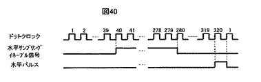
水平エリア検出カウンタ15121の動作例を図40を用いて説明する。水平エリア検出カウンタ15121は水平イネーブル信号の開始点、及び終了点のx座標である40,280と、水平パルスを生成するため表示装置16の水平方向画素数:320をプリセットしているものとする。プリセットする方法はCPU7から設定しても良いし、水平エリア検出カウンタ15121内部で固定しても良い。このように水平エリア検出カウンタ15121に初期値をプリセットすることにより水平エリア検出カウンタ15121は入力されたドットクロックをカウントし、40クロックカウントした時点で出力をHighレベルに遷移させ、280クロックカウントした時点で出力を再びLowレベルに遷移させる。さらに320をカウントした時点でHighレベルとなる水平パルスを出力する。尚、本水平エリア検出カウンタ15121は水平パルスを出力した時点でカウント値をリセットして再び“0”からカウントを再開し、周期的に上述のタイミングで水平検出エリアイネーブル信号及び、水平パルス出力を出力する動作を繰り返す。
An operation example of the horizontal
垂直エリア検出カウンタ15122の動作例を図41を用いて説明する。垂直エリア検出カウンタ15122は垂直検出エリアイネーブル信号を開始点、及び終了点のx座標である1,320と、垂直パルスを生成するため表示装置16の水平方向画素数:320をプリセットしているものとする。プリセットする方法はCPU7から設定しても良いし、垂直エリア検出カウンタ15122内部で固定しても良い。このように垂直エリア検出カウンタ15122に初期値をプリセットすることにより垂直位置カウンタ15122は入力された水平パルスをカウントし、1クロックカウントした時点で出力をHighレベルに遷移させ、320クロックカウントした時点、即ち、常にHighレベルを垂直検出エリアイネーブル信号として出力する。さらに180をカウントした時点でHighレベルとなる垂直パルスを出力する。尚、本垂直エリア検出カウンタ15122は垂直パルスを出力した時点でカウント値をリセットして再び“0”からカウントを再開し、周期的に上述のタイミングで水平検出エリアイネーブル信号及び、水平パルス出力を出力する動作を繰り返す。ここでは、図39に示すように黒の無画エリアがコンテンツ表示エリアの左右のみに挿入された映像信号が入力された場合の例について説明するが、これに限られるものでなく、コンテンツ表示エリアの上下にあっても構わない。その場合にはコンテンツ表示エリアの垂直方向のスタート位置と終了位置をCPU7から設定すればよい。
An operation example of the vertical
アンドゲート15123の入出力波形を図42に示す。アンドゲート15113の出力は水平イネーブル信号及び、垂直イネーブル信号が共にHighレベルの時のみHighレベルを出力する。よって、水平方向は40ドットから280ドットまで、垂直方向は1ドットから180ドットまでの期間、即ち、コンテンツ表示エリアの映像信号が流れている期間Highレベルが出力される。
An input / output waveform of the AND
オアゲート15124はアンドゲート15123の出力と、I/F部155から入力されたエリア検出マスク信号とアンドゲート15113の論理和をサンプリングイネーブル信号として特徴点検出部154に出力する。このアンドゲート15123によってCPU7からI/F部155を介してアンドゲート15113の出力を特徴点検出部154にそのまま伝えるか、Highに固定してマスクするか制御することができる。これによって、特徴点検出を黒の無画エリアを含む画面全域で行うか、黒の無画エリアを含まないコンテンツ表示エリアのみで行うかをCPU7が制御することができる。ここでは後者の場合の例について説明するが、黒の無画エリアの面積が小さい場合には前者としてもさほど問題は無い。
The OR
次に、I/F部155における黒の無画エリアの判定フローを図43を用いて説明する。S4301で垂直パルスを受信したか判定する。受信した場合は、パターン部分検出部1511から各検出ポイントの輝度信号Yの値を取得する(S4302)。S4303で各検出ポイントにおける前フレームとの差分を求める。S4304ではP11,P12,P13、即ち4:3映像を表示した場合にパターン部分になる部分について前フレームとの差分が“0”か判定する。この差分が“0”でないときは、パターン部分が含まれていないと判断し、S4310に移行する。
Next, the determination flow of the black no-image area in the I /
一方、差分が“0”の場合はS4305に移行する。S4305ではP21,P22,P23即ち、4:3映像を表示した場合にコンテンツ表示領域になる部分について前フレームとの差分が“0”か判定する。この差分が“0”の時はパターン部分ではないと判断し、S4310に移行する。 On the other hand, if the difference is “0”, the flow shifts to S4305. In S4305, it is determined whether P21, P22, and P23, that is, the portion that becomes the content display area when displaying 4: 3 video, is “0” from the previous frame. When this difference is “0”, it is determined that the pattern portion is not present, and the flow shifts to S4310.
P21,P22,P23が“0”でないときは、パターン部分であると判断し、S4306においてパターン部分が黒の無画エリア部分であるか否かの判定を行う。P11,P12,P13における輝度信号Yの値が“0”でないとき、パターン部分は壁紙部分であるとして、レジスタの一部に設けている壁紙部分の有無を示すフラグを“1”:「壁紙部分有り」に設定する(S4307)。輝度信号Yの値が“0”の場合は、黒の無画エリアであると判断し、無画エリアの有無を示すフラグを“1”:「無画エリア有り」に設定する(S4308)。 When P21, P22, and P23 are not “0”, it is determined that the pattern portion is a pattern portion, and it is determined whether or not the pattern portion is a black no-image area portion in S4306. When the value of the luminance signal Y in P11, P12, and P13 is not “0”, the pattern portion is assumed to be a wallpaper portion, and a flag indicating the presence / absence of the wallpaper portion provided in a part of the register is set to “1”: “wallpaper portion” Set to “present” (S4307). If the value of the luminance signal Y is “0”, it is determined that the area is a black no-image area, and a flag indicating the presence / absence of the no-image area is set to “1”: “no image area exists” (S4308).
S4309ではCPU7に対して割り込みを発行してレジスタのリードを要求し、壁紙部分付きか、または無画エリア付きコンテンツであることをCPU7に通知する。S4310では各検出ポイントの輝度信号Yの値を保存し、前フレームデータとする。
In step S4309, an interrupt is issued to the
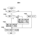
図44にCPU7での処理フローを示す。CPU7での補正特性更新処理はI/F部155からの割り込み141を受信により実行する。S4401において、CPU7は壁紙フラグが“1”の時、すなわち、黒の無画エリア部分のパターン部分が含まれている場合は、S4403において補正データ=“0”とし、S4406に移行する。一方、壁紙フラグが“0”の場合は、S4402に移行する。
FIG. 44 shows a processing flow in the
S4402において無画フラグが“1”の時、すなわち、黒一色の無画エリアが含まれている場合は、一定値以下の入力階調に対する出力を“0”に固定し、無画エリア付きコンテンツに適した高画質化処理を施すための補正データを算出すると共に、特徴点検出エリアを決定する(S4405)。なお、無画エリア付きのコンテンツに適した高画質化処理については後に説明する。 When the no-image flag is “1” in S4402, that is, when a black one-color no-image area is included, the output for the input gradation below a certain value is fixed to “0”, and the content with the no-image area Correction data for performing image quality enhancement processing suitable for the image quality is calculated, and a feature point detection area is determined (S4405). Note that the high image quality processing suitable for content with a non-image area will be described later.
また、S4402において無画フラグが“0”の場合、通常の高画質化処理を施すための補正データを算出する(S4404)。S4406では、上記I/F部153に補正データを転送する。
If the no-image flag is “0” in S4402, correction data for performing normal image quality improvement processing is calculated (S4404). In S4406, the correction data is transferred to the I /
以下、図45に示す黒の無画エリア部分付きコンテンツが入力された場合の動作例について説明する。図45(a)は前フレームの映像であり、図に示すように4:3コンテンツの左右に無画エリア部分が挿入されている。このような映像信号が入力された場合、前フレームの輝度信号Yの値として図45(c)のフレーム1の列に示す様にP11:0,P12:0,P13:0,P21:100,P22:50,P23:40が保持されているものとする。図43のフロー図において、S4301で垂直パルス検出後、S4302において図45(b)における各検出ポイントの輝度信号Yの値としては図45(c)フレーム2の列に示す様にP11:0,P12:0,P13:0,P21:80,P22:80,P23:50を取得し、S4303に移行する。S4303においてはフレーム1とフレーム2の差分を算出するため、図45(c)のフレーム差分の列に示す様に△P11:0,△P12:0,△P13:0,△P21:−10,△P22:30,△P23:10となる。次に、S4304において、△P11,△P12及び△P13が“0”のため、S4305に移行し、△P21,△P22,△P23が“0“か判定する。この結果、△P21,△P22,△P23は“0”ではないため、S4306に移行する。
Hereinafter, an example of operation when the content with the black non-image area portion shown in FIG. 45 is input will be described. FIG. 45A shows the image of the previous frame, and as shown in the figure, non-image area portions are inserted on the left and right of the 4: 3 content. When such a video signal is input, the value of the luminance signal Y of the previous frame is P11: 0, P12: 0, P13: 0, P21: 100, as shown in the column of
S4306においてP11,P12,P13は“0”のためS4308に移行する。S4308において無画フラグ=“1”をレジスタにセットしてS4309に移行する。S4309においてCPU7に対して割り込みを発行してレジスタリードを要求し、無画エリア部分付きのコンテンツであることをCPU7に通知してS4310に移行する。S4310において各検出ポイントの輝度信号Yの値を保持して終了する。
In S4306, since P11, P12, and P13 are “0”, the process proceeds to S4308. In step S4308, the no-image flag = "1" is set in the register, and the process proceeds to step S4309. In step S4309, an interrupt is issued to the
なお、S4405では、無画エリア部分付きのコンテンツに適した補正特性として、例えば0〜15の入力階調が存在するコンテンツであっても、図46に示すように入力信号0〜15に対する出力を0に固定するよう補正する。このように補正することによって、黒側の階調の一部が失われるが、無画エリア部分に含まれるノイズを除去し、パターン部分を均一な黒として表示できるメリットがあり、画像として見栄えを良くすることができる。
Note that in S4405, as a correction characteristic suitable for content with a non-image area portion, for example, even for content with input gradations of 0 to 15, output for
また、黒の無画エリア部分による画像の特徴点計算への影響を排除するため、コンテンツ表示エリアの座標を特定して水平位置カウンタ15111及び、垂直位置カウンタ15112に所望のカウント値を設定し、オアゲート15124にLowを出力するようI/F部153に出力する値を設定する。そして、S4406において、I/F部153に上記設定値を設定することにより、無画エリア部分付きのコンテンツに最適な画質補正を行うことができる。
In addition, in order to eliminate the influence on the feature point calculation of the image by the black no-image area portion, the coordinates of the content display area are specified, and desired count values are set in the
なお、本実施例では黒の無画エリア部分付きコンテンツが入力された際には、映像信号の補正を行う場合について説明したが、これに限られるものでなく、白の無画エリア部分が含まれる場合に補正を行うようにしても良い。この場合、図43のS4306において、P11等が255であるか否かを判定する。また、一定値以上の白側の階調を“255”に固定するように制御することにより、ノイズが含まれている場合でも、パターン部分のちらつきを防止することができる。 In this embodiment, the case where the video signal is corrected when content with a black no-image area portion is input has been described. However, the present invention is not limited to this and includes a white no-image area portion. In this case, correction may be performed. In this case, in S4306 of FIG. 43, it is determined whether or not P11 is 255. Further, by controlling so that the gray level on the white side of a certain value or more is fixed to “255”, flickering of the pattern portion can be prevented even when noise is included.
また、図37では、特徴点エリア制御部1512を特徴点検出部154側のみに設けているが、変調部152側にも設けることにより変調エリアの制御も行うことができる。これによって、例えばパターン部分を除外し、コンテンツ表示エリアのみ補正を行うことができる。また、黒や白の無画エリアではなく、例えば絵柄があるパターン部分であっても、ある一定レベル以下の階調に全ての階調が分布する場合は、出力を“0”として黒一色としても良いし、逆にある一定レベル以上の階調に全ての階調が分布する場合は、出力を“255”として白一色としても良い。
In FIG. 37, the feature point
なお、以上の実施例では、画像左右にパターン部分が付加されている場合を例にとって説明したが、これに限られるものでなく、画像の上下にパターン部分が含まれる場合に適用しても良い。画像上下のパターン部分を検出するためには、検出ポイントを画像上下に設けることで同様の処理方式にて対応することができる。 In the above embodiment, the case where the pattern portions are added to the left and right of the image has been described as an example. However, the present invention is not limited to this, and may be applied to the case where the pattern portions are included above and below the image. . In order to detect the pattern portions at the top and bottom of the image, the same processing method can be used by providing detection points at the top and bottom of the image.
さらに、画面上の時刻表示や画面周辺部に挿入される字幕やマークが含まれている場合がある。このような場合に対応するために、パターン部分検出部1511の判定結果と関係なく、あらかじめ画面の上下左右の一定部分を特徴点検出エリアから除外し、画面中央部のみで特徴点検出を行うようにしても良い。これにより、字幕などの挿入による特徴点データの変化を抑制し画面のちらつきや色の変化を防止することができる。
Furthermore, there may be cases where subtitles or marks inserted in the time display on the screen or in the periphery of the screen are included. In order to deal with such a case, regardless of the determination result of the pattern
1…通信アンテナ、2…無線回路、3…符号復号処理回路、4…マイク、5…レシーバ、
6…キー、7…CPU、8…CPUバス、9…メモリ、10…DAC、11…スピーカー、12…TVアンテナ、13…TVチューナー、14…ビデオI/F、15…高画質化回路、16…表示装置、17…バックライト、18…バックライト駆動回路、19…電源回路、20…バッテリー、151…RGB-YUV変換回路、152…変調部、153…色差-HS変換部、154…特徴点検出部、155…I/F部、156…HS-色差変換、157…YUV-RGB変換部、158…セレクタ、159…電源OFF可能エリア、1551…内部バス、1541…輝度特徴点検出部、1542…色相特徴点検出部、1543…彩度特徴点検出部、1510…RGBゲイン調整部、21…照度センサ、171…R-LED、172…G-LED、173…B-LED、181…制御回路、182…DC-DCコンバーター、183〜185…電流制御手段、141…INT、21…照度センサ、1511…パターン部分検出部、15111…水平位置カウンタ、15112…垂直意図カウンタ、15113…アンドゲート、15114…ラッチ、P11,P12,P13,P21,P22,P23…検出ポイント、1512…特徴点エリア制御部、15121…水平エリア検出カウンタ、15122…垂直エリア検出カウンタ、15123…アンドゲート、15124…オアゲート
DESCRIPTION OF
6 ... key, 7 ... CPU, 8 ... CPU bus, 9 ... memory, 10 ... DAC, 11 ... speaker, 12 ... TV antenna, 13 ... TV tuner, 14 ... video I / F, 15 ... high image quality circuit, 16
Claims (3)
前記入力部に入力された映像信号にコンテンツ以外のパターン部分が含まれているか否かを検出するパターン検出部と、
前記入力部に入力された映像信号の輝度または色相または彩度のうちの少なくとも1つのレベルあるいは分布を検出する特徴点検出部と、
前記特徴点検出部により検出された輝度または色相または彩度のうちの少なくとも1つのレベルあるいは分布を用いて補正データを生成する制御部と、
前記制御部により生成された補正データを用いて前記入力部に入力された映像信号を補正する補正部と、を備え、
前記制御部は、前記パターン検出部により検出されたパターン部分が、前記コンテンツの左右または上下に付加されて表示される模様または有彩色の単一色により構成されているか、あるいは黒一色または白一色により構成されているかを検出し、前記パターン部分が前記コンテンツの左右または上下に付加されて表示される模様または有彩色の単一色により構成されていることを検出した場合に前記補正データの更新を停止し、前記パターン部分が前記コンテンツの左右または上下に付加されて表示される黒一色または白一色により構成されていることを検出した場合に前記補正データを更新するように制御することを特徴とする映像処理装置。 An input unit to which a video signal including content is input;
A pattern detection unit for detecting whether or not a pattern portion other than the content is included in the video signal input to the input unit;
A feature point detection unit that detects at least one level or distribution of luminance, hue, or saturation of the video signal input to the input unit;
A control unit that generates correction data using at least one level or distribution of luminance, hue, or saturation detected by the feature point detection unit;
And a correcting unit for correcting the input video signal to the input unit using the correction data generated by the control unit,
The control unit is configured such that a pattern portion detected by the pattern detection unit is configured by a single color of a pattern or a chromatic color that is displayed by being added to the left or right or top and bottom of the content, or by one black or one white color detecting whether the constructed, stops updating of the correction data when the pattern portion is detected that is formed by single color right or added to by the pattern or chromatic display up and down of the content The correction data is controlled to be updated when it is detected that the pattern portion is composed of one black color or one white color displayed by being added to the left or right or top and bottom of the content. Video processing device.
前記制御部は、前記パターン部分が前記コンテンツの左右または上下に付加されて表示される黒一色により構成されていることを検出した場合、前記特徴点検出部により検出された輝度レベルの入力階調が所定値未満である階調エリアに対応する補正値を固定し、前記入力階調が所定値以上である階調エリアに対応する補正値を前記特徴点検出部により検出された輝度レベルに応じて補正値を変化させた補正データに更新し、
前記補正部は、更新された補正データを用いて前記入力部に入力された映像信号を補正することを特徴とする請求項1に記載の映像処理装置。 The feature point detection unit detects a luminance level of the video signal input to the input unit,
Wherein, when the pattern part has detected that it is constituted by a solid black to be displayed is added to the left and right or top and bottom of the content, the input gradation of the luminance level detected by the feature point detection unit The correction value corresponding to the gradation area in which the input gradation is less than the predetermined value is fixed, and the correction value corresponding to the gradation area in which the input gradation is greater than or equal to the predetermined value is determined according to the luminance level detected by the feature point detection unit. Update the correction data with the correction value changed,
The video processing apparatus according to claim 1, wherein the correction unit corrects the video signal input to the input unit using the updated correction data .
前記制御部は、前記パターン部分が前記コンテンツの左右または上下に付加されて表示される白一色により構成されていることを検出した場合、前記特徴点検出部により検出された輝度レベルの入力階調が所定値以上である階調エリアに対応する補正値を固定し、前記入力階調が所定値未満である階調エリアに対応する補正値を前記特徴点検出部により検出された輝度レベルに応じて補正値を変化させた補正データに更新し、
前記補正部は、更新された補正データを用いて前記入力部に入力された映像信号を補正することを特徴とする請求項1に記載の映像処理装置。 The feature point detection unit detects a luminance level of the video signal input to the input unit,
Wherein, when the pattern part has detected that it is constituted by a solid white to be displayed is added to the left and right or top and bottom of the content, the input gradation of the luminance level detected by the feature point detection unit The correction value corresponding to the gradation area where is greater than or equal to the predetermined value is fixed, and the correction value corresponding to the gradation area where the input gradation is less than the predetermined value is determined according to the luminance level detected by the feature point detection unit. Update the correction data with the correction value changed,
The video processing apparatus according to claim 1, wherein the correction unit corrects the video signal input to the input unit using the updated correction data .
Priority Applications (7)
| Application Number | Priority Date | Filing Date | Title |
|---|---|---|---|
| JP2005338000A JP4626497B2 (en) | 2005-11-24 | 2005-11-24 | Video processing device and portable terminal device |
| US11/602,956 US7952645B2 (en) | 2005-11-24 | 2006-11-22 | Video processing apparatus and mobile terminal apparatus |
| EP06255978.6A EP1791351B1 (en) | 2005-11-24 | 2006-11-22 | Video processing apparatus and mobile terminal |
| KR1020060116442A KR100842498B1 (en) | 2005-11-24 | 2006-11-23 | Image processing device |
| CN2006101468137A CN1972457B (en) | 2005-11-24 | 2006-11-24 | Video processing apparatus and portable mobile terminal |
| KR1020080026977A KR100895738B1 (en) | 2005-11-24 | 2008-03-24 | Image processing device |
| US13/082,797 US8289450B2 (en) | 2005-11-24 | 2011-04-08 | Video processing apparatus with corrector for correcting an input video signal |
Applications Claiming Priority (1)
| Application Number | Priority Date | Filing Date | Title |
|---|---|---|---|
| JP2005338000A JP4626497B2 (en) | 2005-11-24 | 2005-11-24 | Video processing device and portable terminal device |
Publications (3)
| Publication Number | Publication Date |
|---|---|
| JP2007150379A JP2007150379A (en) | 2007-06-14 |
| JP2007150379A5 JP2007150379A5 (en) | 2007-11-01 |
| JP4626497B2 true JP4626497B2 (en) | 2011-02-09 |
Family
ID=37696126
Family Applications (1)
| Application Number | Title | Priority Date | Filing Date |
|---|---|---|---|
| JP2005338000A Active JP4626497B2 (en) | 2005-11-24 | 2005-11-24 | Video processing device and portable terminal device |
Country Status (5)
| Country | Link |
|---|---|
| US (2) | US7952645B2 (en) |
| EP (1) | EP1791351B1 (en) |
| JP (1) | JP4626497B2 (en) |
| KR (2) | KR100842498B1 (en) |
| CN (1) | CN1972457B (en) |
Families Citing this family (27)
| Publication number | Priority date | Publication date | Assignee | Title |
|---|---|---|---|---|
| US7746411B1 (en) | 2005-12-07 | 2010-06-29 | Marvell International Ltd. | Color management unit |
| US8406514B2 (en) * | 2006-07-10 | 2013-03-26 | Nikon Corporation | Image processing device and recording medium storing image processing program |
| KR100886339B1 (en) * | 2007-01-09 | 2009-03-03 | 삼성전자주식회사 | Method and apparatus for classifying Image based on the Image Feature |
| US8150097B2 (en) * | 2007-01-24 | 2012-04-03 | Sony Corporation | Concealed metadata transmission system |
| JP4279318B2 (en) * | 2007-02-02 | 2009-06-17 | 三菱電機株式会社 | Video display device |
| US8548049B2 (en) * | 2007-07-02 | 2013-10-01 | Vixs Systems, Inc | Pattern detection module, video encoding system and method for use therewith |
| JP2010139782A (en) | 2008-12-11 | 2010-06-24 | Sony Corp | Display device, method for driving the display device, and program |
| JP2010147538A (en) | 2008-12-16 | 2010-07-01 | Sony Corp | Image processing apparatus, method, and program |
| EP2523187A4 (en) * | 2010-01-08 | 2014-01-01 | Sharp Kk | Electronic device, method for adjusting color saturation, program therefor, and recording medium |
| US8487951B2 (en) * | 2010-06-24 | 2013-07-16 | Motorola Mobility Llc | Devices and methods of user interfaces to generate a high current drain impact user notification relating to a wallpaper image |
| JP2012019381A (en) * | 2010-07-08 | 2012-01-26 | Sony Corp | Image processor and image processing method |
| KR101675852B1 (en) * | 2010-07-23 | 2016-11-14 | 엘지디스플레이 주식회사 | Video display device for compensating defect |
| JP5950652B2 (en) * | 2011-04-08 | 2016-07-13 | ローム株式会社 | Image processing circuit, semiconductor device, and image processing device |
| JP5924147B2 (en) * | 2012-06-14 | 2016-05-25 | ソニー株式会社 | Display device, image processing device, and display method |
| CN103514926B (en) * | 2012-06-29 | 2017-07-21 | 富泰华工业(深圳)有限公司 | Test system and method for testing |
| JP6389729B2 (en) * | 2013-10-22 | 2018-09-12 | 株式会社ジャパンディスプレイ | Display device and color conversion method |
| JP6389728B2 (en) * | 2013-10-22 | 2018-09-12 | 株式会社ジャパンディスプレイ | Display device and color conversion method |
| JP6514482B2 (en) * | 2013-10-22 | 2019-05-15 | 株式会社ジャパンディスプレイ | Display device and color conversion method |
| JP6543442B2 (en) * | 2014-07-30 | 2019-07-10 | ルネサスエレクトロニクス株式会社 | Image processing apparatus and image processing method |
| US9613408B2 (en) * | 2014-09-25 | 2017-04-04 | Intel Corporation | High dynamic range image composition using multiple images |
| JP2016114789A (en) * | 2014-12-15 | 2016-06-23 | 株式会社ジャパンディスプレイ | Display device and color conversion method |
| CN105744351A (en) * | 2016-02-15 | 2016-07-06 | 四川长虹电器股份有限公司 | Realization method of virtual microphone of Android smart television |
| CN106250827B (en) * | 2016-07-20 | 2019-06-11 | 浙江宇视科技有限公司 | Vehicle color identification method and device |
| KR101996646B1 (en) * | 2017-03-30 | 2019-10-01 | 주식회사 아나패스 | Display driving method and display driving apparatus |
| CN108921843B (en) * | 2018-07-05 | 2022-08-12 | 深圳市路畅科技股份有限公司 | System and method for detecting performance of vehicle-mounted navigator |
| CN113053324A (en) * | 2021-03-15 | 2021-06-29 | 生迪智慧科技有限公司 | Backlight control method, device, equipment, system and storage medium |
| CN113676624A (en) * | 2021-06-30 | 2021-11-19 | 西人马帝言(北京)科技有限公司 | Image acquisition method, device, equipment and storage medium |
Citations (2)
| Publication number | Priority date | Publication date | Assignee | Title |
|---|---|---|---|---|
| JPH0530386A (en) * | 1991-07-24 | 1993-02-05 | Sanyo Electric Co Ltd | Television receiver |
| JP2004336664A (en) * | 2003-05-12 | 2004-11-25 | Sony Corp | Contrast processing circuit for video signal |
Family Cites Families (30)
| Publication number | Priority date | Publication date | Assignee | Title |
|---|---|---|---|---|
| US5442406A (en) | 1990-06-01 | 1995-08-15 | Thomson Consumer Electronics, Inc. | Wide screen television |
| US5486871A (en) * | 1990-06-01 | 1996-01-23 | Thomson Consumer Electronics, Inc. | Automatic letterbox detection |
| CN1026446C (en) | 1990-06-22 | 1994-11-02 | 佳能株式会社 | Image processing apparatus and method |
| DE69127591T2 (en) | 1990-06-22 | 1998-01-22 | Canon Kk | Device and method for processing images |
| JP2692406B2 (en) * | 1991-04-04 | 1997-12-17 | 松下電器産業株式会社 | Video signal enlargement device |
| JPH06315098A (en) | 1993-04-30 | 1994-11-08 | Matsushita Electric Ind Co Ltd | Vertical outline correcting device |
| US5363143A (en) * | 1993-09-03 | 1994-11-08 | Thomson Consumer Electronics, Inc. | Side by side picture display with reduced cropping |
| US6002797A (en) * | 1994-06-22 | 1999-12-14 | Hitachi, Ltd. | Apparatus for detecting position of featuring region of picture, such as subtitle or imageless part |
| JPH0993548A (en) * | 1995-09-27 | 1997-04-04 | Toshiba Corp | Television receiver with teletext information display function |
| KR970060961A (en) * | 1996-01-18 | 1997-08-12 | 김광호 | Adaptive gamma correction device using integral look-up table |
| JP3745907B2 (en) * | 1998-11-27 | 2006-02-15 | パイオニア・マイクロ・テクノロジー株式会社 | Video signal processing method |
| JP4613403B2 (en) * | 2000-08-25 | 2011-01-19 | ソニー株式会社 | Image display apparatus and method |
| JP2002132225A (en) | 2000-10-24 | 2002-05-09 | Sharp Corp | Video signal corrector and multimedia computer system using the same |
| KR100396683B1 (en) * | 2001-01-08 | 2003-09-03 | 엘지전자 주식회사 | Method and apparatus for correcting screen brightness/chromaticity of TV |
| CA2417169C (en) | 2001-05-31 | 2009-04-28 | Matsushita Electric Industrial Co., Ltd. | Image processing apparatus and image processing method |
| KR100739137B1 (en) | 2001-06-19 | 2007-07-13 | 엘지전자 주식회사 | Method to adjust image signal for digital television |
| EP1271459A1 (en) * | 2001-06-27 | 2003-01-02 | Deutsche Thomson-Brandt Gmbh | Method and device for compensating burning effects on display panel |
| JP3928424B2 (en) | 2001-12-26 | 2007-06-13 | コニカミノルタビジネステクノロジーズ株式会社 | Flicker correction for movies |
| WO2003077542A1 (en) * | 2002-03-11 | 2003-09-18 | Koninklijke Philips Electronics N.V. | Image display apparatus |
| JP2003348488A (en) | 2002-05-30 | 2003-12-05 | Canon Inc | Image display system and image display method |
| JP4006628B2 (en) * | 2002-07-03 | 2007-11-14 | ソニー株式会社 | Information processing apparatus, information processing method, recording medium, and program |
| US7079192B1 (en) * | 2002-07-30 | 2006-07-18 | The Regents Of The University Of California | Letter box line blackener for the HDTV/conventional-analog hybrid system |
| JP2004096593A (en) | 2002-09-03 | 2004-03-25 | Hitachi Ltd | Communication terminal |
| KR20040048791A (en) | 2002-12-03 | 2004-06-10 | 삼성전자주식회사 | Apparatus and Method for adaptive brightness control |
| US20040109091A1 (en) | 2002-12-03 | 2004-06-10 | Samsung Electronics Co., Ltd. | Apparatus and method for adaptive brightness control |
| JP3819870B2 (en) * | 2003-04-25 | 2006-09-13 | 三洋電機株式会社 | Image display device |
| JP4079102B2 (en) | 2003-05-22 | 2008-04-23 | ソニー株式会社 | Display device and image display method |
| JP2005026814A (en) | 2003-06-30 | 2005-01-27 | Sharp Corp | Video display apparatus |
| JP2005159693A (en) * | 2003-11-26 | 2005-06-16 | Olympus Corp | Image processing apparatus |
| US7268799B2 (en) * | 2004-12-03 | 2007-09-11 | Motorola, Inc. | Multi-function device illumination control system and method |
-
2005
- 2005-11-24 JP JP2005338000A patent/JP4626497B2/en active Active
-
2006
- 2006-11-22 EP EP06255978.6A patent/EP1791351B1/en active Active
- 2006-11-22 US US11/602,956 patent/US7952645B2/en active Active
- 2006-11-23 KR KR1020060116442A patent/KR100842498B1/en active IP Right Grant
- 2006-11-24 CN CN2006101468137A patent/CN1972457B/en active Active
-
2008
- 2008-03-24 KR KR1020080026977A patent/KR100895738B1/en active IP Right Grant
-
2011
- 2011-04-08 US US13/082,797 patent/US8289450B2/en active Active
Patent Citations (2)
| Publication number | Priority date | Publication date | Assignee | Title |
|---|---|---|---|---|
| JPH0530386A (en) * | 1991-07-24 | 1993-02-05 | Sanyo Electric Co Ltd | Television receiver |
| JP2004336664A (en) * | 2003-05-12 | 2004-11-25 | Sony Corp | Contrast processing circuit for video signal |
Also Published As
| Publication number | Publication date |
|---|---|
| KR20080030998A (en) | 2008-04-07 |
| KR100895738B1 (en) | 2009-04-30 |
| KR100842498B1 (en) | 2008-07-01 |
| CN1972457B (en) | 2010-06-16 |
| US8289450B2 (en) | 2012-10-16 |
| US20070115392A1 (en) | 2007-05-24 |
| EP1791351A3 (en) | 2008-10-15 |
| JP2007150379A (en) | 2007-06-14 |
| EP1791351B1 (en) | 2014-04-30 |
| KR20070055383A (en) | 2007-05-30 |
| US20110181785A1 (en) | 2011-07-28 |
| EP1791351A2 (en) | 2007-05-30 |
| CN1972457A (en) | 2007-05-30 |
| US7952645B2 (en) | 2011-05-31 |
Similar Documents
| Publication | Publication Date | Title |
|---|---|---|
| JP4626497B2 (en) | Video processing device and portable terminal device | |
| JP4736487B2 (en) | Video processing device | |
| JP5527195B2 (en) | Video display device | |
| US8228438B2 (en) | Image processing method capable of improving the display quality of image frames | |
| JP5383995B2 (en) | Apparatus and method for improving video visibility | |
| JP4676364B2 (en) | Color correction method, color correction apparatus, and color correction program | |
| CN101841724B (en) | Image processing method | |
| JP2003209855A (en) | Image observing apparatus | |
| US7023496B2 (en) | Moving picture decoding display apparatus and method for controlling a video signal's contrast and brightness when a video signal update is detected | |
| JP2006146245A (en) | Mobile communication terminal having apparatus and method of displaying improved color image | |
| US20040263663A1 (en) | Digital camera image controller apparatus for a mobile phone | |
| KR100605841B1 (en) | Apparatus and method for compensation of correlated color temperature of gray scale in lce | |
| US10205967B2 (en) | Extended YCC format for backward-compatible P3 camera video | |
| US20060022924A1 (en) | Head drum assembly for magnetic recording and reproducing apparatus | |
| JP4660827B2 (en) | Video signal processing apparatus, contrast control method, and program | |
| JP5026731B2 (en) | On-screen display translucent realization apparatus, realization system and realization method | |
| KR20040033545A (en) | System for Display Control of Mobile Phone and Method Thereof | |
| JP2004333839A (en) | Picture display device and mobile electronic equipment | |
| KR20080029416A (en) | Method and apparatus for adjusting image according to lightness of backlight | |
| JP2005323175A (en) | Portable equipment | |
| KR100669607B1 (en) | Display control apparatus for each mode of mobile terminal |
Legal Events
| Date | Code | Title | Description |
|---|---|---|---|
| RD04 | Notification of resignation of power of attorney |
Free format text: JAPANESE INTERMEDIATE CODE: A7424 Effective date: 20060426 |
|
| A521 | Request for written amendment filed |
Free format text: JAPANESE INTERMEDIATE CODE: A523 Effective date: 20070914 |
|
| A621 | Written request for application examination |
Free format text: JAPANESE INTERMEDIATE CODE: A621 Effective date: 20070914 |
|
| A977 | Report on retrieval |
Free format text: JAPANESE INTERMEDIATE CODE: A971007 Effective date: 20091217 |
|
| A131 | Notification of reasons for refusal |
Free format text: JAPANESE INTERMEDIATE CODE: A131 Effective date: 20100105 |
|
| A521 | Request for written amendment filed |
Free format text: JAPANESE INTERMEDIATE CODE: A523 Effective date: 20100308 |
|
| A131 | Notification of reasons for refusal |
Free format text: JAPANESE INTERMEDIATE CODE: A131 Effective date: 20100727 |
|
| A521 | Request for written amendment filed |
Free format text: JAPANESE INTERMEDIATE CODE: A523 Effective date: 20100916 |
|
| TRDD | Decision of grant or rejection written | ||
| A01 | Written decision to grant a patent or to grant a registration (utility model) |
Free format text: JAPANESE INTERMEDIATE CODE: A01 Effective date: 20101012 |
|
| A01 | Written decision to grant a patent or to grant a registration (utility model) |
Free format text: JAPANESE INTERMEDIATE CODE: A01 |
|
| A61 | First payment of annual fees (during grant procedure) |
Free format text: JAPANESE INTERMEDIATE CODE: A61 Effective date: 20101025 |
|
| FPAY | Renewal fee payment (event date is renewal date of database) |
Free format text: PAYMENT UNTIL: 20131119 Year of fee payment: 3 |
|
| R151 | Written notification of patent or utility model registration |
Ref document number: 4626497 Country of ref document: JP Free format text: JAPANESE INTERMEDIATE CODE: R151 |
|
| FPAY | Renewal fee payment (event date is renewal date of database) |
Free format text: PAYMENT UNTIL: 20131119 Year of fee payment: 3 |
|
| S111 | Request for change of ownership or part of ownership |
Free format text: JAPANESE INTERMEDIATE CODE: R313113 |
|
| R350 | Written notification of registration of transfer |
Free format text: JAPANESE INTERMEDIATE CODE: R350 |
|
| R250 | Receipt of annual fees |
Free format text: JAPANESE INTERMEDIATE CODE: R250 |
|
| R250 | Receipt of annual fees |
Free format text: JAPANESE INTERMEDIATE CODE: R250 |
|
| R250 | Receipt of annual fees |
Free format text: JAPANESE INTERMEDIATE CODE: R250 |
|
| S111 | Request for change of ownership or part of ownership |
Free format text: JAPANESE INTERMEDIATE CODE: R313111 |
|
| R250 | Receipt of annual fees |
Free format text: JAPANESE INTERMEDIATE CODE: R250 |
|
| R350 | Written notification of registration of transfer |
Free format text: JAPANESE INTERMEDIATE CODE: R350 |
|
| R250 | Receipt of annual fees |
Free format text: JAPANESE INTERMEDIATE CODE: R250 |
|
| R250 | Receipt of annual fees |
Free format text: JAPANESE INTERMEDIATE CODE: R250 |