EP1223661A2 - Automotive alternator - Google Patents
Automotive alternator Download PDFInfo
- Publication number
- EP1223661A2 EP1223661A2 EP02000162A EP02000162A EP1223661A2 EP 1223661 A2 EP1223661 A2 EP 1223661A2 EP 02000162 A EP02000162 A EP 02000162A EP 02000162 A EP02000162 A EP 02000162A EP 1223661 A2 EP1223661 A2 EP 1223661A2
- Authority
- EP
- European Patent Office
- Prior art keywords
- phase
- winding
- rotor
- stator
- portions
- Prior art date
- Legal status (The legal status is an assumption and is not a legal conclusion. Google has not performed a legal analysis and makes no representation as to the accuracy of the status listed.)
- Granted
Links
Images


Classifications
-
- H—ELECTRICITY
- H02—GENERATION; CONVERSION OR DISTRIBUTION OF ELECTRIC POWER
- H02K—DYNAMO-ELECTRIC MACHINES
- H02K9/00—Arrangements for cooling or ventilating
- H02K9/02—Arrangements for cooling or ventilating by ambient air flowing through the machine
- H02K9/04—Arrangements for cooling or ventilating by ambient air flowing through the machine having means for generating a flow of cooling medium
- H02K9/06—Arrangements for cooling or ventilating by ambient air flowing through the machine having means for generating a flow of cooling medium with fans or impellers driven by the machine shaft
-
- H—ELECTRICITY
- H02—GENERATION; CONVERSION OR DISTRIBUTION OF ELECTRIC POWER
- H02K—DYNAMO-ELECTRIC MACHINES
- H02K3/00—Details of windings
- H02K3/04—Windings characterised by the conductor shape, form or construction, e.g. with bar conductors
- H02K3/24—Windings characterised by the conductor shape, form or construction, e.g. with bar conductors with channels or ducts for cooling medium between the conductors
-
- H—ELECTRICITY
- H02—GENERATION; CONVERSION OR DISTRIBUTION OF ELECTRIC POWER
- H02K—DYNAMO-ELECTRIC MACHINES
- H02K19/00—Synchronous motors or generators
- H02K19/16—Synchronous generators
- H02K19/22—Synchronous generators having windings each turn of which co-operates alternately with poles of opposite polarity, e.g. heteropolar generators
Definitions
- the present invention relates to an automotive alternator and particularly to a positional relationship between a cooling fan and a stator winding.
- Figure 10 is a cross section showing a conventional automotive alternator.
- the automotive alternator includes: a case 3 constituted by an aluminum front bracket 1 and an aluminum rear bracket 2; a shaft 6 disposed inside the case 3 having a pulley 4 secured to a first end thereof; a Lundell-type rotor 7 secured to the shaft 6; front-end and rear-end centrifugal fans 5 functioning as cooling fans secured to front and rear axial end surfaces of the rotor 7; a stator 8 secured to the case 3 so as to envelop the rotor 7; slip rings 9 secured to a second end of the shaft 6 for supplying electric current to the rotor 7; a pair of brushes 10 sliding on surfaces of the slip rings 9; a brush holder 11 accommodating the brushes 10; a rectifier 12 electrically connected to the stator 8 for converting alternating current generated in the stator 8 into direct current; and a regulator 18 mounted to a regulator heat sink 17 fitted onto the brush holder 11, the regulator 18 adjusting the magnitude of an alternating voltage generated in the stator 8.
- the rotor 7 is constituted by a field winding 13 for generating a magnetic flux on passage of an electric current, and a pair of first and second pole cores 20 and 21 disposed so as to cover the field winding 13, magnetic poles being formed in the first and second pole cores 20 and 21 by magnetic flux generated in the field winding 13.
- the pair of first and second pole cores 20 and 21 are made of iron, each has a plurality of first and second claw-shaped magnetic poles 22 and 23 having a generally trapezoidal outermost diameter surface shape disposed on an outer circumferential edge portion at even angular pitch in a circumferential direction so as to project axially, and the first and second pole cores 20 and 21 are fixed to the shaft 6 facing each other such that the first and second claw-shaped magnetic poles 22 and 23 intermesh.
- the stator 8 is constituted by: a cylindrical stator core 15 formed by laminating a magnetic steel plate; and a stator winding 16 installed in the stator core 15.
- the stator 8 is held between the front bracket 1 and the rear bracket 2 so as to form a uniform air gap between outer circumferential surfaces of the claw-shaped magnetic poles 22 and 23 and an inner circumferential surface of the stator core 15.
- the rectifier 12 is constituted by: unidirectional conducting component packages 24 for three-phase full-wave rectification of output from the stator winding 16; a pair of rectifier heat sinks 25; and a circuit board 26 in which wiring constituting a bridge circuit is insert molded.
- the unidirectional conducting component packages 24 are each formed into a generally rectangular parallelepiped shape by molding a diode 24a joined to a heat-dissipating tab 24b into an electrically-insulating resin portion 24c.
- a predetermined number of the unidirectional conducting component packages 24 are mounted to each of the rectifier heat sinks 25 by joining the heat-dissipating tabs 24b to a main surface of each of the rectifier heat sinks 25.
- an electric current is supplied from a battery (not shown) through the brushes 10 and the slip rings 9 to the field winding 13, generating a magnetic flux.
- the first claw-shaped magnetic poles 22 on the first pole core 20 are magnetized into North-seeking (N) poles by this magnetic flux, and the second claw-shaped magnetic poles 23 on the second pole core 21 are magnetized into South-seeking (S) poles.
- the pulley 4 is driven by an engine and the rotor 7 is rotated by the shaft 6.
- a rotating magnetic field is applied to the stator core 15 due to the rotation of the rotor 7, generating an electromotive force in the stator winding 16.
- the alternating electromotive force generated in the stator winding 16 is converted into direct current by the rectifier 12 and the magnitude of the voltage output therefrom is adjusted by the regulator 18, recharging the battery.
- the field winding 13, the stator winding 16, the rectifier 12, and the regulator 18 continuously generate heat during power generation, and in an automotive alternator having a rated output current in the 100A class, the amount of heat generated at rotational frequencies at which the temperature is high is 60W, 500W, 120W, and 6W, respectively.
- front-end and rear-end air intake apertures 1a and 2a are disposed through axial end surfaces of the front bracket 1 and the rear bracket 2
- front-end and rear-end air discharge apertures 1b and 2b are disposed through radial side surfaces of the front bracket 1 and the rear bracket 2 so as to face coil end groups 16f and 16r of the stator winding 16.
- centrifugal fans 5 are rotated and driven together with the rotation of the rotor 7, and front-end and rear-end cooling airflow channels are formed in which external air is sucked inside the case 3 through the front-end and rear-end air intake apertures 1a and 2a, flows axially towards the rotor 7, is then deflected centrifugally by the centrifugal fans 5, thereafter crosses the coil end groups 16f and 16r, and is discharged outside through the front-end and rear-end air discharge apertures 1b and 2b.
- a rotor cooling airflow channel is also formed in which a cooling airflow flows through the inside of the rotor 7 from a front end to a rear end as a result of a pressure difference between the front end and the rear end of the rotor 7.
- heat generated in the stator winding 16 is dissipated from the coil end groups 16f and 16r to the front-end and rear-end cooling airflows, suppressing temperature increases in the stator 8.
- heat generated in the diodes 24a and the regulator 18 is dissipated to the rear-end cooling airflow through the rectifier heat sinks 25 and the regulator heat sink 17, suppressing temperature increases in the rectifier 12 and the regulator 18.
- heat generated in the field winding 13 is dissipated to the rotor cooling airflow flowing through the rotor 7, thereby suppressing temperature increases in the rotor 7.
- heat-generating parts such as the stator 8, the rectifier 12, etc., are cooled by the cooling airflows flowing through the cooling airflow channels formed by the centrifugal fans 5.
- inflow flow rates of the cooling airflows flowing through the cooling airflow channels depend on ventilation resistance in the cooling airflow channels, the inflow flow rates decreasing as ventilation resistance increases.
- This decrease in the inflow flow rates of the cooling airflows causes a decrease in cooling of the rectifier 12 and the regulator 18.
- an amount of overlap between the front-end centrifugal fan 5 and the front-end coil end group 16f and between the rear-end centrifugal fan 5 and the rear-end coil end group 16r is one of the factors increasing ventilation resistance in the cooling airflow channels. In other words, if the amount of overlap increases, ventilation resistance increases. Cooling of the stator winding 16 is raised as the amount of overlap increases.
- stator winding 16 and the rectifier 12 both of which are large heat-generating parts, and investigated problems accompanying temperature increases in the stator winding 16 and the rectifier 12.
- the present invention aims to solve the above problems and an object of the present invention is to provide an automotive alternator enabling the working life of diodes of a rectifier to be extended and deterioration in electrical insulation to be eliminated by setting an amount of overlap between a cooling fan and a coil end group of a stator winding in consideration of a softening temperature of a varnish impregnated into the stator winding and of a heat tolerance threshold of the diodes.
- an automotive alternator including:
- a gap may be formed between the coil end group of the stator winding and an end surface of the stator core, the gap being positioned closer to an axially-central region than the end surface of the rotor to which the cooling fan is fixed.
- Each of winding phase portions constituting the stator winding may be constructed by a divided winding portion.
- the cooling fan may be formed so as to have a smaller outside diameter than an outside diameter of the rotor.
- An intersecting region between an axial end surface of the rotor and an outer circumferential surface of the rotor may be chamfered.
- the cooling fans may be fixed to first and second axial end surfaces of the rotor, the cooling fan fixed to the first axial end surface of the rotor being a centrifugal fan, and the cooling fan fixed to the second axial end surface of the rotor being a mixed-flow fan.
- the slots may be disposed at a ratio of two per phase per pole.
- Figure 1 is a cross section showing an automotive alternator according to Embodiment 1 of the present invention
- Figure 2 is a perspective showing a stator of the automotive alternator according to Embodiment 1 of the present invention
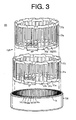
- Figure 3 is an exploded perspective showing the stator of the automotive alternator according to Embodiment 1 of the present invention
- Figure 4 is a circuit diagram showing an electrical circuit in the automotive alternator according to Embodiment 1 of the present invention.
- a rotor 7A is constituted by a field winding 13 for generating magnetic flux on passage of an electric current, and a pair of first and second pole cores 20A and 21A disposed so as to cover the field winding 13, magnetic poles being formed in the first and second pole cores 20A and 21A by magnetic flux generated in the field winding 13.
- the pair of first and second pole cores 20A and 21A are made of iron, each has a plurality of first and second claw-shaped magnetic poles 22 and 23 having a generally trapezoidal outermost diameter surface shape disposed on an outer circumferential edge portion at even angular pitch in a circumferential direction so as to project axially, intersecting regions between axial end surfaces and outer circumferential surfaces of the first and second pole cores 20A and 21A are chamfered into a curved shape to form first and second shoulder portions 20a and 21a, and the first and second pole cores 20A and 21A are fixed to a shaft 6 facing each other such that the first and second claw-shaped magnetic poles 22 and 23 intermesh.
- Front-end and rear-end centrifugal fans 38 functioning as cooling fans are fixed to the axial end surfaces of the first and second pole cores 20A and 21A such that the outside diameters of the centrifugal fans 38 are generally aligned with boundary portions between the axial end surfaces of the first and second pole cores 20A and 21A and the first and second shoulder portions 20a and 21a.
- a stator 8A is constituted by: a cylindrical stator core 15A formed by laminating a magnetic steel plate; and a stator winding 16A installed in the stator core 15A.
- the stator 8A is held between the front bracket 1 and the rear bracket 2 so as to form a uniform air gap between outer circumferential surfaces of the claw-shaped magnetic poles 22 and 23 and an inner circumferential surface of the stator core 15A.
- a ratio (t/h) between an amount of axial protrusion t of the centrifugal fans 38 relative to apex portions of front-end and rear-end coil end groups 16f and 16r of the stator winding 16A and an axial height h of the centrifugal fans 38 is 0.5.
- stator 8A Next, a construction of the stator 8A will be explained with reference to Figures 2 to 3.
- Slots 14 extending axially are disposed in the stator core 15A at an even angular pitch (a pitch corresponding to an electrical angle of 30°) in a circumferential direction at a ratio of two per phase per pole.
- seventy-two slots 14 are disposed in the stator core 15A so as to obtain the stator winding 16A, which is composed of first and second three-phase alternating-current windings.
- the slots 14 are disposed in order of an a-phase slot 14a, a d-phase slot 14d, a b-phase slot 14b, an e-phase slot 14e, a c-phase slot 14c, and an f-phase slots 14f repeatedly in a circumferential direction. Moreover, the slots 14 in each phase are disposed at a pitch of six slots.
- An a-phase winding phase portion 30a is constructed into a wave winding in which a conductor wire composed of a continuous copper wire coated with electrical insulation is wound for a predetermined number of winds, the a-phase winding phase portion 30a being formed into a wave-shaped pattern composed of twelve slot-housed portions 31a disposed at a pitch of six slots (6P) in a circumferential direction and linking portions 31b linking together end portions of adjacent pairs of the slot-housed portions 31a alternately at first and second axial ends, as shown in Figure 3.
- the a-phase winding phase portion 30a is installed in the stator core 15A such that the slot-housed portions 31a are housed in the respective a-phase slots 14a disposed at the pitch of six slots.
- the linking portions 31b linking together the end portions of the adjacent pairs of the slot-housed portions 31a extend circumferentially axially outside the stator core 15A, constituting coil ends. Furthermore, b-phase, c-phase, d-phase, e-phase, and f-phase winding phase portions 30b, 30c, 30d, 30e, and 30f are constructed in a similar manner.
- the a-phase, b-phase, and c-phase winding phase portions 30a, 30b, and 30c are installed in the stator core 15A so as to be circumferentially offset from each other by a pitch of two slots (2P) and stacked in three layers radially.
- the f-phase, d-phase, and e-phase winding phase portions 30f, 30d, and 30e are installed in the stator core 15A so as to be circumferentially offset from each other by a pitch of two slots, to be stacked in three layers radially, and to be positioned on an inner circumferential side of the a-phase, b-phase, and c-phase winding phase portions 30a, 30b, and 30c.
- the stator 8A is obtained, in which the six winding phase portions 30a to 30f are installed in the stator core 15A so as to be stacked in six layers radially.
- the coil ends (the linking portions 31b) of the six winding phase portions 30a to 30f constitute the front-end and rear-end coil end groups 16f and 16r of the stator winding 16A.
- portions of the coil ends extending circumferentially relative to the stator core 15A form front-end and rear-end crossover portions 16b, and gaps G are formed between the front-end and rear-end crossover portions 16b and front-end and rear-end end surfaces of the stator core 15A.
- a varnish is impregnated inside the slots 14 housing the stator winding 16A, fixing the stator winding 16A to the stator core 15A.
- the a-phase, b-phase, and c-phase winding phase portions 30a, 30b, and 30c constructed in this manner are formed into a Y-connection (an alternating-current connection), constituting a first three-phase alternating-current winding 160A, and the d-phase, e-phase, and f-phase winding phase portions 30d, 30e, and 30f are formed into a Y-connection (an alternating-current connection), constituting a second three-phase alternating-current winding 160B.
- the stator winding 16A is constituted by the first and second three-phase alternating-current windings 160A and 160B.
- the first and second three-phase alternating-current windings 160A and 160B are each connected to separate rectifiers 12, constituting the electrical circuit shown in Figure 4.
- the a-phase, b-phase, and c-phase winding phase portions 30a, 30b, and 30c are each given a phase difference corresponding to an electrical angle of 60°
- the d-phase, e-phase, and f-phase winding phase portions 30d, 30e, and 30f are each given a phase difference corresponding to an electrical angle of 60°
- the d-phase, e-phase, and f-phase winding phase portions 30d, 30e, and 30f are given a phase difference corresponding to an electrical angle of 30° relative to the a-phase, b-phase, and c-phase winding phase portions 30a, 30b, and 30c, respectively.
- a rotating magnetic field is applied to the stator core 15A due to the rotation of the rotor 7A, generating an electromotive force in the first and second three-phase alternating-current windings 160A and 160B of the stator winding 16A.
- the alternating electromotive force generated in the first and second three-phase alternating-current windings 160A and 160B is converted into direct current by the respective rectifier 12, and the magnitudes of the voltages output therefrom are adjusted by the regulator 18. Then, the output from each of the rectifiers 12 is combined, recharging the battery.
- Embodiment 1 because the ratio (t/h) between the amount of axial protrusion t of the centrifugal fans 38 relative to the apex portions of the front-end and rear-end coil end groups 16f and 16r of the stator winding 16A and the axial height h of the centrifugal fans 38 is 0.5, inflow flow rates of the cooling airflows are ensured, enabling temperature increases in the diodes 24a of the rectifiers 12 to be lowered without detracting from the cooling of the front-end and rear-end coil end groups 16f and 16r. Thus, because heat degradation in the diodes 24a is suppressed, the life of the diodes 24a can be extended.
- centrifugal fans 38 are constructed so as to have smaller outside diameters than the first and second pole cores 20A and 21A, a radial distance between the front-end centrifugal fan 38 and the front-end coil end group 16f increases, and a radial distance between the rear-end centrifugal fan 38 and the rear-end coil end group 16r increases, thereby lowering wind noise resulting from interference between the front-end centrifugal fan 38 and the front-end coil end group 16f and between the rear-end centrifugal fan 38 and the rear-end coil end group 16r.
- first and second curved shoulder portions 20a and 21a are formed on the first and second pole cores 20A and 21A, wind-splitting noise generated by the first and second curved shoulder portions 20a and 21a is ameliorated, lowering wind noise.
- the slots 14 are formed at a ratio of two per phase per pole, the amount of time that a tooth formed between the slots 14 overlaps an adjacent pair of the magnetic poles relative to a radial direction is shortened. As a result, magnetic flux leakage is lowered, suppressing decreases of effective magnetic flux. In addition, generation of surges in the magnetic flux is suppressed, reducing fluctuations in generated voltage and output waveform disturbances, thereby reducing ripples when alternating current is converted into direct current.
- Figure 5 shows values of increases in saturation temperatures from an ambient temperature when power was generated at full load under stable output conditions in an automotive alternator mounted with the stator 8A in which the height of the apex portions of the front-end and rear-end coil end groups 16f and 16r of the stator winding 16A was varied, and the saturation temperatures of the stator 8A and the rectifiers 12 (the diodes 24a) were measured.
- the ratio (t/h) between the amount of axial protrusion t of the centrifugal fans 38 and the axial height h of the centrifugal fans 38 is represented on the horizontal axis
- temperature changes ⁇ T (°C) in the diodes 24a and the stator 8A from the ambient temperature of the experiment (20°C) are represented on first and second vertical axes, respectively.
- the temperature change ⁇ T in the stator 8A is indicated by a broken line
- the temperature change ⁇ T in the diodes 24a is indicated by a solid line.
- the automotive alternator was operated at 2000, 2500, 3000, 4000, and 5000 rpm, the saturation temperatures of the stator 8A and the diodes 24a were measured, and the largest values in the measured saturation temperatures were used as the saturation temperatures of the stator 8A and the diodes 24a.
- the ambient temperature is 90°C under the worst operating conditions.
- the heat tolerance threshold of the diodes 24a is 165°C.
- an automotive alternator can be achieved in which the life of the diodes 24a can be extended and the deterioration of electrical insulation is suppressed.
- the axial distance L being measured between end surfaces of the front-end crossover portions 16b of the front-end coil end group 16f of the stator winding 16A nearest to the stator core 15A and a front-end fan-mounting surface, and between end surfaces of the rear-end crossover portions 16b of the rear-end coil end group 16r of the stator winding 16A nearest to the stator core 15A and a rear-end fan-mounting surface.
- Figure 6 shows measured results for wind noise in an automotive alternator when operated at 10,000 rpm, the automotive alternator being mounted with the stator 8A, in which the axial height of the gaps G between the front-end and rear-end crossover portions 16b of the front-end and rear-end coil end groups 16f and 16r and the front-end and rear-end end surfaces of the stator core 15A was varied.
- the axial distance L (mm) between the end surfaces of the front-end crossover portions 16b nearest to the stator core 15A and the front-end fan-mounting surface and between the end surfaces of the rear-end crossover portions 16b nearest to the stator core 15A and the rear-end fan-mounting surface is represented on the horizontal axis, and an overall value of wind noise (dB) is represented on the vertical axis.
- the number of gaps G increases as the number of slots increases.
- the frequency generated by the wind noise resulting from the circumferential irregularities constituted by the gaps G rises as the gaps G increase in number.
- the wind noise becomes high order wind noise, that is, unpleasantly irritating noise.
- L > generation of such unpleasantly irritating noise can be suppressed.
- the effect of preventing the generation of unpleasantly irritating noise by making L > 0 becomes evident when the slots are disposed at a ratio of two or more per phase per pole.
- the six winding phase portions 30a to 30f are installed in the stator core 15A so as to line up from an outer circumferential side in order of the a-phase winding phase portion 30a, the b-phase winding phase portion 30b, the c-phase winding phase portion 30c, the f-phase winding phase portion 30f, the d-phase winding phase portion 30d, and the e-phase winding phase portion 30e.
- the six winding phase portions 30a to 30f are not limited to this installation order.
- Figure 7 is a cross section showing an automotive alternator according to Embodiment 2 of the present invention
- Figure 8 is a perspective showing a stator of the automotive alternator according to Embodiment 2 of the present invention
- Figure 9 is an exploded perspective of a stator winding installed in the stator of the automotive alternator according to Embodiment 2 of the present invention
- a mixed-flow fan 39 functioning as a cooling fan is fixed to the axial end surface (the fan-mounting surface) of the first pole core 20A.
- a stator 8B is constituted by the stator core 15A, and a stator winding 16B installed in the stator core 15A. As described below, each of the winding phase portions of the stator winding 16B is installed in the stator core 15A as a divided winding portion.
- An a-phase winding phase portion 40a is constructed into a wave winding in which a conductor wire composed of a continuous copper wire coated with electrical insulation is wound for a predetermined number of winds, and as shown in Figure 9, the a-phase winding phase portion 40a is formed into a divided winding portion having a wave-shaped pattern composed of twelve slot-housed portions 41a disposed at a pitch of six slots (6P) in a circumferential direction and linking portions 41b linking together a first half of end portions of adjacent pairs of the slot-housed portions 41a alternately at first and second axial ends and linking together a second half of the end portions alternately at the first and second axial ends.
- 6P six slots
- the a-phase winding phase portion 40a is installed in the stator core 15A such that the slot-housed portions 41a are housed in the respective a-phase slots 14a disposed at the pitch of six slots.
- the linking portions 41b linking together the end portions of the adjacent pairs of the slot-housed portions 41a extend circumferentially axially outside the stator core 15A, constituting coil ends.
- a first half of the linking portions 41b extending outwards from any given a-phase slot 14a extends to a first circumferential side and enters a subsequent a-phase slot 14a on the first circumferential side
- a second half thereof extends to a second circumferential side and enters a subsequent a-phase slot 14a on the second circumferential side.
- b-phase, c-phase, d-phase, e-phase, and f-phase winding phase portions 40b, 40c, 40d, 40e, and 40f are constructed in a similar manner.
- the a-phase and e-phase winding phase portions 40a and 40e are circumferentially offset from each other by a pitch of three slots (3P) and stacked in two layers radially, and installed in the stator core 15A so as to constitute two layers on an outer circumferential side in a radial direction.
- the d-phase and c-phase winding phase portions 40d and 40c are circumferentially offset from each other by a pitch of three slots and stacked in two layers radially, and installed in the stator core 15A so as to constitute two layers in an intermediate portion in the radial direction.
- the b-phase and f-phase winding phase portions 40b and 40f are circumferentially offset from each other by a pitch of three slots and stacked in two layers radially, and installed in the stator core 15A so as to constitute two layers on an inner circumferential side in the radial direction.
- the stator 8B is obtained, in which the six winding phase portions 40a to 40f are installed in the stator core 15A so as to be stacked in six layers radially.
- the six winding phase portions 40a to 40f are installed in the stator core 15A so as to line up from the outer circumferential side in order of the a-phase winding phase portion 40a, the e-phase winding phase portion 40e, the d-phase winding phase portion 40d, the c-phase winding phase portion 40c, the b-phase winding phase portion 40b, and the f-phase winding phase portion 40f.
- the coil ends (the linking portions 41b) of the six winding phase portions 40a to 40f constitute front-end and rear-end coil end groups 16f and 16r of the stator winding 16B. Furthermore, portions of the coil ends extending circumferentially relative to the stator core 15A form front-end and rear-end crossover portions, and gaps G are formed between the front-end and rear-end crossover portions and the front-end and rear-end end surfaces of the stator core 15A.
- the a-phase, b-phase, and c-phase winding phase portions 40a, 40b, and 40c constructed in this manner are formed into a Y-connection (an alternating-current connection), constituting a first three-phase alternating-current winding, and the d-phase, e-phase, and f-phase winding phase portions 40d, 40e, and 40f are formed into a Y-connection (an alternating-current connection), constituting a second three-phase alternating-current winding.
- the first and second three-phase alternating-current windings are each connected to separate rectifiers 12, constituting a similar electrical circuit to the electrical circuit shown in Figure 4.
- the a-phase, b-phase, and c-phase winding phase portions 40a, 40b, and 40c are each given a phase difference corresponding to an electrical angle of 60°
- the d-phase, e-phase, and f-phase winding phase portions 40d, 40e, and 40f are each given a phase difference corresponding to an electrical angle of 60°
- the d-phase, e-phase, and f-phase winding phase portions 40d, 40e, and 40f are given a phase difference corresponding to an electrical angle of 30° relative to the a-phase, b-phase, and c-phase winding phase portions 40a, 40b, and 40c, respectively.
- the stator 8B constructed in this manner is mounted to the automotive alternator in place of the stator 8A and operates in a similar manner to Embodiment 1 above.
- Embodiment 2 because the front-end cooling fan is constituted by the mixed-flow fan 39, the cooling airflow which flows in through the front-end air intake aperture 1a is made to flow radially outward and axially rearward by the mixed-flow fan 39. Hence, the flow rate of the cooling airflow flowing through the inside of the rotor 7A from the front end to the rear end is ensured, reliably cooling the field winding 13. Thus, temperature increases in the field winding 13 are suppressed, enabling improved output.
- the winding phase portions 40a to 40f constituting the stator winding 16B are each constituted by divided winding portions, the linking portions 41b (coil ends) of each of the winding phase portions 40a to 40f extending from the slots 14 are divided in half onto the first and second circumferential sides. Hence, radial overlap between bundles of the conductor wires constituting the winding phase portions 40a to 40f in the vicinity of where the winding phase portions 40a to 40f bend circumferentially after extending from the slots 14 is distributed circumferentially, reducing radial expansion of the coil end groups 16f and 16r.
- the six winding phase portions 40a to 40f are installed in the stator core 15A so as to line up from the outer circumferential side in order of the a-phase winding phase portion 40a, the e-phase winding phase portion 40e, the d-phase winding phase portion 40d, the c-phase winding phase portion 40c, the b-phase winding phase portion 40b, and the f-phase winding phase portion 40f.
- the coil ends (the linking portions 41b) of the first three-phase alternating-current winding and the coil ends (the linking portions 41b) of the second three-phase alternating-current winding are arranged in a balanced manner in the radial direction.
- the coil ends of the first three-phase alternating-current winding and the coil ends of the second three-phase alternating-current winding are uniformly cooled by the cooling airflows supplied by the cooling fans 38 and 39, enabling temperature increases in the stator 8B to be suppressed by preventing the temperature of either of the three-phase alternating-current windings from increasing excessively.
- the a-phase winding phase portion 40a and the e-phase winding phase portion 40e which constitute a pair of layers on the outer circumferential side in the radial direction, are arranged such that the linking portions 41b of the e-phase winding phase portion 40e extend outward from the e-phase slots 14e at a circumferentially-central portions of the linking portions 41b of the a-phase winding phase portion 40a.
- portions of the coil ends in the vicinity of where the a-phase winding phase portion 40a and the e-phase winding phase portion 40e are bent circumferentially after extending from the slots 14 (portions where radial expansion is greatest) are maximally separated in the circumferential direction.
- the d-phase winding phase portion 40d and the c-phase winding phase portion 40c which constitute a pair of layers in the intermediate portion in the radial direction, are arranged such that the linking portions 41b of the d-phase winding phase portion 40d extend outward from the d-phase slots 14d at circumferentially-central portions of the linking portions 41b of the c-phase winding phase portion 40c.
- portions of the coil ends in the vicinity of where the d-phase winding phase portion 40d and the c-phase winding phase portion 40c are bent circumferentially after extending from the slots 14 are maximally separated in the circumferential direction.
- the b-phase winding phase portion 40b and the f-phase winding phase portion 40f which constitute a pair of layers on the inner circumferential side in the radial direction, are arranged such that the linking portions 41b of the f-phase winding phase portion 40f extend outward from the f-phase slots 14f at circumferentially-central portions of the linking portions 41b of the b-phase winding phase portion 40b.
- portions of the coil ends in the vicinity of where the b-phase winding phase portion 40b and the f-phase winding phase portion 40f are bent circumferentially after extending from the slots 14 are maximally separated in the circumferential direction.
- the six winding phase portions 40a to 40f are installed in the stator core 15A so as to line up from the outer circumferential side in order of the a-phase winding phase portion 40a, the e-phase winding phase portion 40e, the d-phase winding phase portion 40d, the c-phase winding phase portion 40c, the b-phase winding phase portion 40b, and the f-phase winding phase portion 40f.
- the six winding phase portions 40a to 40f are not limited to this installation order.
- the d-phase, e-phase, and f-phase winding phase portions 30d, 30e, and 30f are given a phase difference corresponding to an electrical angle of 30° relative to the a-phase, b-phase, and c-phase winding phase portions 30a, 30b, and 30c, respectively, but the phase difference between the d-phase, e-phase, and f-phase winding phase portions 30d, 30e, and 30f and the a-phase, b-phase, and c-phase winding phase portions 30a, 30b, and 30c is not limited to (an electrical angle of) 30°; the phase difference between the two may also be (an electrical angle of) 32.5°, for example. In that case, twelfth order electromagnetic vibrational forces, which are a cause of unpleasant higher harmonic noise, are reduced.
- a wave winding composed of one conductor wire is used in each of the winding phase portions of the stator winding, but in the present invention, the winding phase portions are not limited to a wave winding composed of one conductor wire; a wave winding constructed by linking short conductor segments, for example, may also be used.
- the present invention is constructed in the above manner and exhibits the effects described below.
- an automotive alternator including:
- a gap may be formed between the coil end group of the stator winding and an end surface of the stator core, the gap being positioned closer to an axially-central region than the end surface of the rotor to which the cooling fan is fixed, suppressing the generation of unpleasantly irritating noise resulting from the gap.
- Each of winding phase portions constituting the stator winding may be constructed by a divided winding portion, reducing circumferential irregularities in the coil end group, thereby reducing wind noise resulting from the circumferential irregularities.
- the cooling fan may be formed so as to have a smaller outside diameter than an outside diameter of the rotor, ensuring radial distance between the fan and the coil end group, thereby lowering wind noise.
- An intersecting region between an axial end surface of the rotor and an outer circumferential surface of the rotor may be chamfered, reducing wind-splitting noise.
- the cooling fans may be fixed to first and second axial end surfaces of the rotor, the cooling fan fixed to the first axial end surface of the rotor being a centrifugal fan, and the cooling fan fixed to the second axial end surface of the rotor being a mixed-flow fan, whereby a cooling airflow flowing through the inside of the rotor is reliably ensured, suppressing temperature increases in a field winding, thereby enabling output to be improved.
- the slots may be disposed at a ratio of two per phase per pole, reducing magnetic flux leakage, thereby suppressing decreases in effective magnetic flux, and also reducing ripples when alternating current is converted into direct current.
Landscapes
- Engineering & Computer Science (AREA)
- Power Engineering (AREA)
- Motor Or Generator Cooling System (AREA)
- Synchronous Machinery (AREA)
- Windings For Motors And Generators (AREA)
Abstract
Description
- The present invention relates to an automotive alternator and particularly to a positional relationship between a cooling fan and a stator winding.
- Figure 10 is a cross section showing a conventional automotive alternator.
- In Figure 10, the automotive alternator includes: a
case 3 constituted by an aluminumfront bracket 1 and an aluminumrear bracket 2; ashaft 6 disposed inside thecase 3 having apulley 4 secured to a first end thereof; a Lundell-type rotor 7 secured to theshaft 6; front-end and rear-endcentrifugal fans 5 functioning as cooling fans secured to front and rear axial end surfaces of the rotor 7; astator 8 secured to thecase 3 so as to envelop the rotor 7;slip rings 9 secured to a second end of theshaft 6 for supplying electric current to the rotor 7; a pair ofbrushes 10 sliding on surfaces of theslip rings 9; abrush holder 11 accommodating thebrushes 10; arectifier 12 electrically connected to thestator 8 for converting alternating current generated in thestator 8 into direct current; and aregulator 18 mounted to aregulator heat sink 17 fitted onto thebrush holder 11, theregulator 18 adjusting the magnitude of an alternating voltage generated in thestator 8. - The rotor 7 is constituted by a field winding 13 for generating a magnetic flux on passage of an electric current, and a pair of first and
second pole cores second pole cores second pole cores magnetic poles second pole cores shaft 6 facing each other such that the first and second claw-shapedmagnetic poles - The
stator 8 is constituted by: acylindrical stator core 15 formed by laminating a magnetic steel plate; and a stator winding 16 installed in thestator core 15. Thestator 8 is held between thefront bracket 1 and therear bracket 2 so as to form a uniform air gap between outer circumferential surfaces of the claw-shapedmagnetic poles stator core 15. - The
rectifier 12 is constituted by: unidirectional conductingcomponent packages 24 for three-phase full-wave rectification of output from the stator winding 16; a pair ofrectifier heat sinks 25; and acircuit board 26 in which wiring constituting a bridge circuit is insert molded. The unidirectional conductingcomponent packages 24 are each formed into a generally rectangular parallelepiped shape by molding adiode 24a joined to a heat-dissipatingtab 24b into an electrically-insulatingresin portion 24c. A predetermined number of the unidirectional conductingcomponent packages 24 are mounted to each of therectifier heat sinks 25 by joining the heat-dissipating tabs 24b to a main surface of each of therectifier heat sinks 25. - In an automotive alternator constructed in this manner, an electric current is supplied from a battery (not shown) through the
brushes 10 and theslip rings 9 to the field winding 13, generating a magnetic flux. The first claw-shapedmagnetic poles 22 on thefirst pole core 20 are magnetized into North-seeking (N) poles by this magnetic flux, and the second claw-shapedmagnetic poles 23 on thesecond pole core 21 are magnetized into South-seeking (S) poles. - At the same time, the
pulley 4 is driven by an engine and the rotor 7 is rotated by theshaft 6. A rotating magnetic field is applied to thestator core 15 due to the rotation of the rotor 7, generating an electromotive force in the stator winding 16. The alternating electromotive force generated in the stator winding 16 is converted into direct current by therectifier 12 and the magnitude of the voltage output therefrom is adjusted by theregulator 18, recharging the battery. - Now, the field winding 13, the stator winding 16, the
rectifier 12, and theregulator 18 continuously generate heat during power generation, and in an automotive alternator having a rated output current in the 100A class, the amount of heat generated at rotational frequencies at which the temperature is high is 60W, 500W, 120W, and 6W, respectively. - Thus, in order to cool the heat generated by power generation, front-end and rear-end
air intake apertures front bracket 1 and therear bracket 2, and front-end and rear-endair discharge apertures front bracket 1 and therear bracket 2 so as to facecoil end groups - Thus, the
centrifugal fans 5 are rotated and driven together with the rotation of the rotor 7, and front-end and rear-end cooling airflow channels are formed in which external air is sucked inside thecase 3 through the front-end and rear-endair intake apertures centrifugal fans 5, thereafter crosses thecoil end groups air discharge apertures - As a result, heat generated in the stator winding 16 is dissipated from the
coil end groups stator 8. Furthermore, heat generated in thediodes 24a and theregulator 18 is dissipated to the rear-end cooling airflow through therectifier heat sinks 25 and theregulator heat sink 17, suppressing temperature increases in therectifier 12 and theregulator 18. In addition, heat generated in the field winding 13 is dissipated to the rotor cooling airflow flowing through the rotor 7, thereby suppressing temperature increases in the rotor 7. - In the automotive alternator constructed in this manner, heat-generating parts such as the
stator 8, therectifier 12, etc., are cooled by the cooling airflows flowing through the cooling airflow channels formed by thecentrifugal fans 5. - Here, inflow flow rates of the cooling airflows flowing through the cooling airflow channels depend on ventilation resistance in the cooling airflow channels, the inflow flow rates decreasing as ventilation resistance increases. This decrease in the inflow flow rates of the cooling airflows causes a decrease in cooling of the
rectifier 12 and theregulator 18. Furthermore, an amount of overlap between the front-endcentrifugal fan 5 and the front-endcoil end group 16f and between the rear-endcentrifugal fan 5 and the rear-endcoil end group 16r (an axial length of radial overlap between the two in each case) is one of the factors increasing ventilation resistance in the cooling airflow channels. In other words, if the amount of overlap increases, ventilation resistance increases. Cooling of the stator winding 16 is raised as the amount of overlap increases. - Thus, increasing the amount of overlap between the front-end
centrifugal fan 5 and the front-endcoil end group 16f and between the rear-endcentrifugal fan 5 and the rear-endcoil end group 16r leads to improved cooling of the stator winding 16, but causes decreased cooling of therectifier 12 and theregulator 18. - However, one conventional problem has been that temperatures increase excessively either in the stator winding 16 or in the
rectifier 12 and theregulator 18 because the amount of overlap between the front-endcentrifugal fan 5 and the front-endcoil end group 16f and between the rear-endcentrifugal fan 5 and the rear-endcoil end group 16r has been set in consideration either of cooling therectifier 12 and theregulator 18 or of cooling the stator winding 16, but not both. - In view of these conditions, the present applicants have focused on the stator winding 16 and the
rectifier 12, both of which are large heat-generating parts, and investigated problems accompanying temperature increases in the stator winding 16 and therectifier 12. - Excessive increases in the temperature of the stator winding 16 lead to softening of a varnish impregnated in the stator winding 16. As a result, the stator winding 16 rubs against the
stator core 15 due to vibration, damaging an electrically-insulating coating on conductor wires of the stator winding 16, thereby decreasing electrical insulation. - Similarly, excessive increases in the temperature of the
rectifier 12 cause heat degradation in thediodes 24a of therectifier 12, shortening the life of thediodes 24a. - The present invention aims to solve the above problems and an object of the present invention is to provide an automotive alternator enabling the working life of diodes of a rectifier to be extended and deterioration in electrical insulation to be eliminated by setting an amount of overlap between a cooling fan and a coil end group of a stator winding in consideration of a softening temperature of a varnish impregnated into the stator winding and of a heat tolerance threshold of the diodes.
- In order to achieve the above object, according to one aspect of the present invention, there is provided an automotive alternator including:
- a shaft rotatably supported by a case;
- a rotor fixed to the shaft;
- a stator provided with:
- a cylindrical stator core supported by the case so as to envelop the rotor, a plurality of slots extending axially being formed in the stator core so as to line up circumferentially; and
- a stator winding installed in the stator core;
- a rectifier supported by the case so as to face an axial end surface of the rotor; and
- at least one cooling fan fixed to at least one axial end surface of the rotor, wherein the cooling fan is constructed such that a ratio (t/h) between an amount of axial protrusion t of the cooling fan relative to an apex portion of a coil end group of the stator winding and an axial height h of the cooling fan satisfies an expression 0.2 < t/h < 0.7.
-
- A gap may be formed between the coil end group of the stator winding and an end surface of the stator core, the gap being positioned closer to an axially-central region than the end surface of the rotor to which the cooling fan is fixed.
- Each of winding phase portions constituting the stator winding may be constructed by a divided winding portion.
- The cooling fan may be formed so as to have a smaller outside diameter than an outside diameter of the rotor.
- An intersecting region between an axial end surface of the rotor and an outer circumferential surface of the rotor may be chamfered.
- The cooling fans may be fixed to first and second axial end surfaces of the rotor, the cooling fan fixed to the first axial end surface of the rotor being a centrifugal fan, and the cooling fan fixed to the second axial end surface of the rotor being a mixed-flow fan.
- The slots may be disposed at a ratio of two per phase per pole.
-
- Figure 1 is a cross section showing an automotive alternator
according to
Embodiment 1 of the present invention; - Figure 2 is a perspective showing a stator of the automotive
alternator according to
Embodiment 1 of the present invention; - Figure 3 is an exploded perspective showing the stator of the
automotive alternator according to
Embodiment 1 of the present invention; - Figure 4 is a circuit diagram showing an electrical circuit in the
automotive alternator according to
Embodiment 1 of the present invention; - Figure 5 is a graph showing relationships between t/h and
temperature change ΔT in a diode and between t/h and temperature
change ΔT in the stator in the automotive alternator according to
Embodiment 1 of the present invention; - Figure 6 is a graph showing a relationship between L and wind
noise in the automotive alternator according to
Embodiment 1 of the present invention; - Figure 7 is a cross section showing an automotive alternator
according to
Embodiment 2 of the present invention; - Figure 8 is a perspective showing a stator of the automotive
alternator according to
Embodiment 2 of the present invention; - Figure 9 is an exploded perspective of a stator winding installed in
the stator of the automotive alternator according to
Embodiment 2 of the present invention; and - Figure 10 is a cross section showing a conventional automotive alternator.
-
- The preferred embodiments of the present invention will now be explained with reference to the drawings.
- Figure 1 is a cross section showing an automotive alternator according to
Embodiment 1 of the present invention, Figure 2 is a perspective showing a stator of the automotive alternator according toEmbodiment 1 of the present invention, Figure 3 is an exploded perspective showing the stator of the automotive alternator according toEmbodiment 1 of the present invention, and Figure 4 is a circuit diagram showing an electrical circuit in the automotive alternator according toEmbodiment 1 of the present invention. - In Figure 1, a
rotor 7A is constituted by a field winding 13 for generating magnetic flux on passage of an electric current, and a pair of first andsecond pole cores second pole cores second pole cores magnetic poles second pole cores second shoulder portions second pole cores shaft 6 facing each other such that the first and second claw-shapedmagnetic poles - Front-end and rear-end
centrifugal fans 38 functioning as cooling fans are fixed to the axial end surfaces of the first andsecond pole cores centrifugal fans 38 are generally aligned with boundary portions between the axial end surfaces of the first andsecond pole cores second shoulder portions - A
stator 8A is constituted by: acylindrical stator core 15A formed by laminating a magnetic steel plate; and a stator winding 16A installed in thestator core 15A. Thestator 8A is held between thefront bracket 1 and therear bracket 2 so as to form a uniform air gap between outer circumferential surfaces of the claw-shapedmagnetic poles stator core 15A. - Here, a ratio (t/h) between an amount of axial protrusion t of the
centrifugal fans 38 relative to apex portions of front-end and rear-endcoil end groups centrifugal fans 38 is 0.5. - Moreover, the rest of the embodiment is constructed in a similar manner to the conventional automotive alternator shown in Figure 10.
- Next, a construction of the
stator 8A will be explained with reference to Figures 2 to 3. -
Slots 14 extending axially are disposed in thestator core 15A at an even angular pitch (a pitch corresponding to an electrical angle of 30°) in a circumferential direction at a ratio of two per phase per pole. In other words, for twelve claw-shapedmagnetic poles rotor 7A, seventy-twoslots 14 are disposed in thestator core 15A so as to obtain the stator winding 16A, which is composed of first and second three-phase alternating-current windings. - Here, the
slots 14 are disposed in order of ana-phase slot 14a, a d-phase slot 14d, a b-phase slot 14b, ane-phase slot 14e, a c-phase slot 14c, and an f-phase slots 14f repeatedly in a circumferential direction. Moreover, theslots 14 in each phase are disposed at a pitch of six slots. - An a-phase winding
phase portion 30a is constructed into a wave winding in which a conductor wire composed of a continuous copper wire coated with electrical insulation is wound for a predetermined number of winds, the a-phase windingphase portion 30a being formed into a wave-shaped pattern composed of twelve slot-housedportions 31a disposed at a pitch of six slots (6P) in a circumferential direction and linkingportions 31b linking together end portions of adjacent pairs of the slot-housedportions 31a alternately at first and second axial ends, as shown in Figure 3. The a-phase windingphase portion 30a is installed in thestator core 15A such that the slot-housedportions 31a are housed in the respectivea-phase slots 14a disposed at the pitch of six slots. The linkingportions 31b linking together the end portions of the adjacent pairs of the slot-housedportions 31a extend circumferentially axially outside thestator core 15A, constituting coil ends. Furthermore, b-phase, c-phase, d-phase, e-phase, and f-phase windingphase portions - The a-phase, b-phase, and c-phase winding
phase portions stator core 15A so as to be circumferentially offset from each other by a pitch of two slots (2P) and stacked in three layers radially. Similarly, the f-phase, d-phase, and e-phase windingphase portions stator core 15A so as to be circumferentially offset from each other by a pitch of two slots, to be stacked in three layers radially, and to be positioned on an inner circumferential side of the a-phase, b-phase, and c-phase windingphase portions - Thus, as shown in Figure 2, the
stator 8A is obtained, in which the six windingphase portions 30a to 30f are installed in thestator core 15A so as to be stacked in six layers radially. The coil ends (the linkingportions 31b) of the six windingphase portions 30a to 30f constitute the front-end and rear-endcoil end groups stator core 15A form front-end and rear-end crossover portions 16b, and gaps G are formed between the front-end and rear-end crossover portions 16b and front-end and rear-end end surfaces of thestator core 15A. Moreover, although not shown, a varnish is impregnated inside theslots 14 housing the stator winding 16A, fixing the stator winding 16A to thestator core 15A. - The a-phase, b-phase, and c-phase winding
phase portions phase portions current windings current windings rectifiers 12, constituting the electrical circuit shown in Figure 4. - Moreover, the a-phase, b-phase, and c-phase winding
phase portions phase portions phase portions phase portions - In an automotive alternator constructed in this manner, a rotating magnetic field is applied to the
stator core 15A due to the rotation of therotor 7A, generating an electromotive force in the first and second three-phase alternating-current windings current windings respective rectifier 12, and the magnitudes of the voltages output therefrom are adjusted by theregulator 18. Then, the output from each of therectifiers 12 is combined, recharging the battery. - According to
Embodiment 1, because the ratio (t/h) between the amount of axial protrusion t of thecentrifugal fans 38 relative to the apex portions of the front-end and rear-endcoil end groups centrifugal fans 38 is 0.5, inflow flow rates of the cooling airflows are ensured, enabling temperature increases in thediodes 24a of therectifiers 12 to be lowered without detracting from the cooling of the front-end and rear-endcoil end groups diodes 24a is suppressed, the life of thediodes 24a can be extended. In addition, because temperature increases in thestator 8A are suppressed, softening of the varnish is suppressed, preventing damage to the electrically-insulating coating on the conductor wires of the stator winding 16A resulting from the conductor wires of the stator winding 16A rubbing against thestator core 15A, thereby improving electrical insulation. - Because the
centrifugal fans 38 are constructed so as to have smaller outside diameters than the first andsecond pole cores centrifugal fan 38 and the front-endcoil end group 16f increases, and a radial distance between the rear-endcentrifugal fan 38 and the rear-endcoil end group 16r increases, thereby lowering wind noise resulting from interference between the front-endcentrifugal fan 38 and the front-endcoil end group 16f and between the rear-endcentrifugal fan 38 and the rear-endcoil end group 16r. - Because the first and second
curved shoulder portions second pole cores curved shoulder portions - Because the
slots 14 are formed at a ratio of two per phase per pole, the amount of time that a tooth formed between theslots 14 overlaps an adjacent pair of the magnetic poles relative to a radial direction is shortened. As a result, magnetic flux leakage is lowered, suppressing decreases of effective magnetic flux. In addition, generation of surges in the magnetic flux is suppressed, reducing fluctuations in generated voltage and output waveform disturbances, thereby reducing ripples when alternating current is converted into direct current. - Now, a relationship between the amount of axial protrusion t of the
centrifugal fans 38 relative to the apex portions of the front-end and rear-endcoil end groups centrifugal fans 38 will be investigated. Figure 5 shows values of increases in saturation temperatures from an ambient temperature when power was generated at full load under stable output conditions in an automotive alternator mounted with thestator 8A in which the height of the apex portions of the front-end and rear-endcoil end groups stator 8A and the rectifiers 12 (thediodes 24a) were measured. Moreover, in Figure 5, the ratio (t/h) between the amount of axial protrusion t of thecentrifugal fans 38 and the axial height h of thecentrifugal fans 38 is represented on the horizontal axis, and temperature changes ΔT (°C) in thediodes 24a and thestator 8A from the ambient temperature of the experiment (20°C) are represented on first and second vertical axes, respectively. The temperature change ΔT in thestator 8A is indicated by a broken line, and the temperature change ΔT in thediodes 24a is indicated by a solid line. Furthermore, the automotive alternator was operated at 2000, 2500, 3000, 4000, and 5000 rpm, the saturation temperatures of thestator 8A and thediodes 24a were measured, and the largest values in the measured saturation temperatures were used as the saturation temperatures of thestator 8A and thediodes 24a. Furthermore, t/h = 1 is when the apex portions of the front-end and rear-endcoil end groups second pole cores rotor 7A, and t/h = 0 is when the apex portions of the front-end and rear-endcoil end groups centrifugal fans 38. - It can be seen from Figure 5 that the temperature change ΔT in the
diodes 24a registers 120°C when t/h is 0, drops rapidly as t/h is increased, decreases slowly when t/h exceeds 0.6, and is 95°C when t/h is 1. It is inferred from this that when t/h = 0, ventilation resistance is at a maximum and the inflow flow rates of the cooling airflows are at a minimum because the front-end and rear-endcoil end groups centrifugal fans 38, and thediodes 24a are not being cooled effectively. It is also inferred that as t/h increases, the ventilation resistance decreases and the inflow flow rates of the cooling airflows increases, thereby improving cooling of thediodes 24a and suppressing temperature increases in thediodes 24a. - In an actual automotive alternator, the ambient temperature is 90°C under the worst operating conditions. Furthermore, the heat tolerance threshold of the
diodes 24a is 165°C. Thus, if the temperature change ΔT at the ambient temperature of 90°C is suppressed to 75°C or less, the temperature of thediodes 24a can be prevented from exceeding the heat tolerance threshold even under the worst operating conditions. If decreases in output resulting from reduced field current due to ambient temperature increases are taken into consideration, a temperature change Δ T of 75°C at an ambient temperature of 90°C corresponds to a temperature change ΔT of 105°C (t/h = 0.2) at an ambient temperature of 20°C. Consequently, in consideration of the life (or of heat degradation) of thediodes 24a, it is desirable to set t/h so as to be greater than 0.2. - On the other hand, it can be seen from Figure 5 that the temperature change □T in the
stator 8registers 180°C when t/h is 0, increases slowly as t/h is increased, increases somewhat steeply when t/h exceeds 0.6, and is 230°C when t/h is 1. It is inferred from this that when t/h = 0, almost all of the cooling airflow deflected centrifugally by the front-end and rear-endcentrifugal fans 38 is supplied to the front-end and rear-endcoil end groups coil end groups centrifugal fans 38, effectively cooling the stator winding 16. It is also inferred that as t/h increases, cooling of the front-end and rear-endcoil end groups stator 8 increases because the amount of cooling airflow supplied to the front-end and rear-endcoil end groups centrifugal fans 38 is reduced as a result of the overlap between the front-endcoil end group 16f and the front-endcentrifugal fan 38 and between the rear-endcoil end group 16r and the rear-endcentrifugal fan 38 decreasing. - Now, since the softening temperature of the varnish is 260°C, if the temperature change ΔT at the ambient temperature of 90°C is suppressed to 170°C or less, the temperature of the
stator 8 can be prevented from exceeding the softening temperature of the varnish even under the worst operating conditions. If decreases in output resulting from reduced field current due to ambient temperature increases are taken into consideration, a temperature change ΔT of 170°C at an ambient temperature of 90°C corresponds to a temperature change ΔT of 200°C (t/h = 0.7) at an ambient temperature of 20°C. Consequently, in consideration of softening of the varnish, it is desirable to set t/h to less than 0.7. Thus, deterioration of electrical insulation resulting from loosening of the bonding between the stator winding 16A and thestator core 15A is suppressed. - Thus, by making 0.2 < t/h < 0.7, an automotive alternator can be achieved in which the life of the
diodes 24a can be extended and the deterioration of electrical insulation is suppressed. - Next, a relationship between an axial distance L and wind noise will be investigated, the axial distance L being measured between end surfaces of the front-
end crossover portions 16b of the front-endcoil end group 16f of the stator winding 16A nearest to thestator core 15A and a front-end fan-mounting surface, and between end surfaces of the rear-end crossover portions 16b of the rear-endcoil end group 16r of the stator winding 16A nearest to thestator core 15A and a rear-end fan-mounting surface. Figure 6 shows measured results for wind noise in an automotive alternator when operated at 10,000 rpm, the automotive alternator being mounted with thestator 8A, in which the axial height of the gaps G between the front-end and rear-end crossover portions 16b of the front-end and rear-endcoil end groups stator core 15A was varied. Moreover, in Figure 6, the axial distance L (mm) between the end surfaces of the front-end crossover portions 16b nearest to thestator core 15A and the front-end fan-mounting surface and between the end surfaces of the rear-end crossover portions 16b nearest to thestator core 15A and the rear-end fan-mounting surface is represented on the horizontal axis, and an overall value of wind noise (dB) is represented on the vertical axis. Furthermore, L = 0 is when the end surfaces of thecrossover portions 16b nearest to thestator core 15A align with the front-end and rear-end fan-mounting surfaces, respectively, L > 0 is when the entire axial region of the gaps G overlaps the first andsecond pole cores centrifugal fans 38 in a radial direction. - It can be seen from Figure 6 that when at least a portion of the gaps G overlaps the
centrifugal fans 38 in a radial direction (L < 0), a generally constant loud wind noise (95 dB) is generated, but that wind noise decreases rapidly in a general region where L = 0, and that wind noise is generally constant (85 dB) at L > 0. Wind noise is generated by interference between circumferential irregularities in the front-end and rear-endcoil end groups centrifugal fans 38. Wind noise resulting from the circumferential irregularities constituted by the gaps G, which appear repeatedly in the circumferential direction, is approximately 10 dB. Thus, the wind noise resulting from the circumferential irregularities constituted by the gaps G is prevented by reducing radial overlap between the gaps G and thecentrifugal fans 38. - Consequently, it is desirable to make L > 0 in order to lower wind noise.
- Now, the number of gaps G increases as the number of slots increases. The frequency generated by the wind noise resulting from the circumferential irregularities constituted by the gaps G rises as the gaps G increase in number. In other words, the wind noise becomes high order wind noise, that is, unpleasantly irritating noise. By making L > 0, generation of such unpleasantly irritating noise can be suppressed. The effect of preventing the generation of unpleasantly irritating noise by making L > 0 becomes evident when the slots are disposed at a ratio of two or more per phase per pole. Furthermore, even when the slots are disposed at a ratio of one per phase per pole, making L > 0 when there is a large number of slots (number of magnetic poles: 16; number of slots: 48) is an effective countermeasure from the viewpoint of suppressing the generation of unpleasantly irritating noise.
- Moreover, in
Embodiment 1 above, the six windingphase portions 30a to 30f are installed in thestator core 15A so as to line up from an outer circumferential side in order of the a-phase windingphase portion 30a, the b-phase windingphase portion 30b, the c-phase windingphase portion 30c, the f-phase windingphase portion 30f, the d-phase windingphase portion 30d, and the e-phase windingphase portion 30e. However, the six windingphase portions 30a to 30f are not limited to this installation order. - Figure 7 is a cross section showing an automotive alternator according to
Embodiment 2 of the present invention, Figure 8 is a perspective showing a stator of the automotive alternator according toEmbodiment 2 of the present invention, and Figure 9 is an exploded perspective of a stator winding installed in the stator of the automotive alternator according toEmbodiment 2 of the present invention - In the automotive alternator according to
Embodiment 2 in Figure 7, a mixed-flow fan 39 functioning as a cooling fan is fixed to the axial end surface (the fan-mounting surface) of thefirst pole core 20A. Astator 8B is constituted by thestator core 15A, and a stator winding 16B installed in thestator core 15A. As described below, each of the winding phase portions of the stator winding 16B is installed in thestator core 15A as a divided winding portion. - Moreover, the rest of the embodiment is constructed in a similar manner to
Embodiment 1 above. - A construction of the stator winding 16B will now be explained with reference to Figures 8 and 9.
- An a-phase winding
phase portion 40a is constructed into a wave winding in which a conductor wire composed of a continuous copper wire coated with electrical insulation is wound for a predetermined number of winds, and as shown in Figure 9, the a-phase windingphase portion 40a is formed into a divided winding portion having a wave-shaped pattern composed of twelve slot-housedportions 41a disposed at a pitch of six slots (6P) in a circumferential direction and linkingportions 41b linking together a first half of end portions of adjacent pairs of the slot-housedportions 41a alternately at first and second axial ends and linking together a second half of the end portions alternately at the first and second axial ends. The a-phase windingphase portion 40a is installed in thestator core 15A such that the slot-housedportions 41a are housed in the respectivea-phase slots 14a disposed at the pitch of six slots. The linkingportions 41b linking together the end portions of the adjacent pairs of the slot-housedportions 41a extend circumferentially axially outside thestator core 15A, constituting coil ends. Here, a first half of the linkingportions 41b extending outwards from any givena-phase slot 14a extends to a first circumferential side and enters a subsequenta-phase slot 14a on the first circumferential side, and a second half thereof extends to a second circumferential side and enters a subsequenta-phase slot 14a on the second circumferential side. - Furthermore, b-phase, c-phase, d-phase, e-phase, and f-phase winding
phase portions - The a-phase and e-phase winding
phase portions stator core 15A so as to constitute two layers on an outer circumferential side in a radial direction. Similarly, the d-phase and c-phase windingphase portions stator core 15A so as to constitute two layers in an intermediate portion in the radial direction. In addition, the b-phase and f-phase windingphase portions 40b and 40f are circumferentially offset from each other by a pitch of three slots and stacked in two layers radially, and installed in thestator core 15A so as to constitute two layers on an inner circumferential side in the radial direction. - Thus, as shown in Figure 8, the
stator 8B is obtained, in which the six windingphase portions 40a to 40f are installed in thestator core 15A so as to be stacked in six layers radially. Here, the six windingphase portions 40a to 40f are installed in thestator core 15A so as to line up from the outer circumferential side in order of the a-phase windingphase portion 40a, the e-phase windingphase portion 40e, the d-phase windingphase portion 40d, the c-phase windingphase portion 40c, the b-phase winding phase portion 40b, and the f-phase windingphase portion 40f. The coil ends (the linkingportions 41b) of the six windingphase portions 40a to 40f constitute front-end and rear-endcoil end groups stator core 15A form front-end and rear-end crossover portions, and gaps G are formed between the front-end and rear-end crossover portions and the front-end and rear-end end surfaces of thestator core 15A. - The a-phase, b-phase, and c-phase winding
phase portions phase portions rectifiers 12, constituting a similar electrical circuit to the electrical circuit shown in Figure 4. - Moreover, the a-phase, b-phase, and c-phase winding
phase portions phase portions phase portions phase portions - The
stator 8B constructed in this manner is mounted to the automotive alternator in place of thestator 8A and operates in a similar manner toEmbodiment 1 above. - In
Embodiment 2, because the front-end cooling fan is constituted by the mixed-flow fan 39, the cooling airflow which flows in through the front-endair intake aperture 1a is made to flow radially outward and axially rearward by the mixed-flow fan 39. Hence, the flow rate of the cooling airflow flowing through the inside of therotor 7A from the front end to the rear end is ensured, reliably cooling the field winding 13. Thus, temperature increases in the field winding 13 are suppressed, enabling improved output. - Because the winding
phase portions 40a to 40f constituting the stator winding 16B are each constituted by divided winding portions, the linkingportions 41b (coil ends) of each of the windingphase portions 40a to 40f extending from theslots 14 are divided in half onto the first and second circumferential sides. Hence, radial overlap between bundles of the conductor wires constituting the windingphase portions 40a to 40f in the vicinity of where the windingphase portions 40a to 40f bend circumferentially after extending from theslots 14 is distributed circumferentially, reducing radial expansion of thecoil end groups coil end groups coil end groups rotor 7A and between thecoil end groups centrifugal fan 38 and the mixed-flow fan 39) can be reduced. - In addition, the six winding
phase portions 40a to 40f are installed in thestator core 15A so as to line up from the outer circumferential side in order of the a-phase windingphase portion 40a, the e-phase windingphase portion 40e, the d-phase windingphase portion 40d, the c-phase windingphase portion 40c, the b-phase winding phase portion 40b, and the f-phase windingphase portion 40f. - Now, because the winding phase portions constituting the first three-phase alternating-current winding and the winding phase portions constituting the second three-phase alternating-current winding are lined up alternately in a radial direction, the coil ends (the linking
portions 41b) of the first three-phase alternating-current winding and the coil ends (the linkingportions 41b) of the second three-phase alternating-current winding are arranged in a balanced manner in the radial direction. Thus, the coil ends of the first three-phase alternating-current winding and the coil ends of the second three-phase alternating-current winding are uniformly cooled by the cooling airflows supplied by the coolingfans stator 8B to be suppressed by preventing the temperature of either of the three-phase alternating-current windings from increasing excessively. - The a-phase winding
phase portion 40a and the e-phase windingphase portion 40e, which constitute a pair of layers on the outer circumferential side in the radial direction, are arranged such that the linkingportions 41b of the e-phase windingphase portion 40e extend outward from thee-phase slots 14e at a circumferentially-central portions of the linkingportions 41b of the a-phase windingphase portion 40a. Thus, portions of the coil ends in the vicinity of where the a-phase windingphase portion 40a and the e-phase windingphase portion 40e are bent circumferentially after extending from the slots 14 (portions where radial expansion is greatest) are maximally separated in the circumferential direction. - Similarly, the d-phase winding
phase portion 40d and the c-phase windingphase portion 40c, which constitute a pair of layers in the intermediate portion in the radial direction, are arranged such that the linkingportions 41b of the d-phase windingphase portion 40d extend outward from the d-phase slots 14d at circumferentially-central portions of the linkingportions 41b of the c-phase windingphase portion 40c. Thus, portions of the coil ends in the vicinity of where the d-phase windingphase portion 40d and the c-phase windingphase portion 40c are bent circumferentially after extending from theslots 14 are maximally separated in the circumferential direction. - In addition, the b-phase winding phase portion 40b and the f-phase winding
phase portion 40f, which constitute a pair of layers on the inner circumferential side in the radial direction, are arranged such that the linkingportions 41b of the f-phase windingphase portion 40f extend outward from the f-phase slots 14f at circumferentially-central portions of the linkingportions 41b of the b-phase winding phase portion 40b. Thus, portions of the coil ends in the vicinity of where the b-phase winding phase portion 40b and the f-phase windingphase portion 40f are bent circumferentially after extending from theslots 14 are maximally separated in the circumferential direction. - As a result, radial expansion of the
coil end groups coil end groups coil end groups rotor 7A and between thecoil end groups fans - Now, in
Embodiment 2 above, the six windingphase portions 40a to 40f are installed in thestator core 15A so as to line up from the outer circumferential side in order of the a-phase windingphase portion 40a, the e-phase windingphase portion 40e, the d-phase windingphase portion 40d, the c-phase windingphase portion 40c, the b-phase winding phase portion 40b, and the f-phase windingphase portion 40f. However, the six windingphase portions 40a to 40f are not limited to this installation order. - Moreover, in each of the above embodiments, the d-phase, e-phase, and f-phase winding
phase portions phase portions phase portions phase portions - Each of the above embodiments has been explained with reference to stator cores in which slots are disposed at a ratio of two per phase per pole, but similar effects can also be achieved if the present invention is applied to stator cores in which the slots are disposed at a ratio of one per phase per pole, or three or more per phase per pole.
- In each of the above embodiments a wave winding composed of one conductor wire is used in each of the winding phase portions of the stator winding, but in the present invention, the winding phase portions are not limited to a wave winding composed of one conductor wire; a wave winding constructed by linking short conductor segments, for example, may also be used.
- The present invention is constructed in the above manner and exhibits the effects described below.
- According to one aspect of the present invention, there is provided an automotive alternator including:
- a shaft rotatably supported by a case;
- a rotor fixed to the shaft;
- a stator provided with:
- a cylindrical stator core supported by the case so as to envelop the rotor, a plurality of slots extending axially being formed in the stator core so as to line up circumferentially; and
- a stator winding installed in the stator core;
- a rectifier supported by the case so as to face an axial end surface of the rotor; and
- at least one cooling fan fixed to at least one axial end surface of the rotor, wherein the cooling fan is constructed such that a ratio (t/h) between an amount of axial protrusion t of the cooling fan relative to an apex portion of a coil end group of the stator winding and an axial height h of the cooling fan satisfies an expression 0.2 < t/h < 0.7, thereby providing an automotive alternator in which deterioration in electrical insulation resulting from damage to an electrically-insulating coating on conductor wires is suppressed, and the working life of diodes is extended.
-
- A gap may be formed between the coil end group of the stator winding and an end surface of the stator core, the gap being positioned closer to an axially-central region than the end surface of the rotor to which the cooling fan is fixed, suppressing the generation of unpleasantly irritating noise resulting from the gap.
- Each of winding phase portions constituting the stator winding may be constructed by a divided winding portion, reducing circumferential irregularities in the coil end group, thereby reducing wind noise resulting from the circumferential irregularities.
- The cooling fan may be formed so as to have a smaller outside diameter than an outside diameter of the rotor, ensuring radial distance between the fan and the coil end group, thereby lowering wind noise.
- An intersecting region between an axial end surface of the rotor and an outer circumferential surface of the rotor may be chamfered, reducing wind-splitting noise.
- The cooling fans may be fixed to first and second axial end surfaces of the rotor, the cooling fan fixed to the first axial end surface of the rotor being a centrifugal fan, and the cooling fan fixed to the second axial end surface of the rotor being a mixed-flow fan, whereby a cooling airflow flowing through the inside of the rotor is reliably ensured, suppressing temperature increases in a field winding, thereby enabling output to be improved.
- The slots may be disposed at a ratio of two per phase per pole, reducing magnetic flux leakage, thereby suppressing decreases in effective magnetic flux, and also reducing ripples when alternating current is converted into direct current.
Claims (7)
- An automotive alternator comprising:wherein said cooling fan (38,39) is constructed such that a ratio (t/h) between an amount of axial protrusion t of said cooling fan relative to an apex portion of a coil end group (16f,16r) of said stator winding (16A, 16B) and an axial height h of said cooling fan satisfies an expression 0.2 < t/h < 0.7.a shaft (6) rotatably supported by a case (3);a rotor (7A) fixed to said shaft;a stator (8A,8B) provided with:a cylindrical stator core (15A) supported by said case (3) so as to envelop said rotor (7A), a plurality of slots (14) extending axially being formed in said stator core (15A) so as to line up circumferentially; anda stator winding (16A,16B) installed in said stator core;a rectifier (12) supported by said case (3) so as to face an axial end surface of said rotor (7A); andat least one cooling fan (38,39) fixed to at least one axial end surface of said rotor (7A),
- The automotive alternator according to Claim 1, wherein a gap (G) is formed between said coil end group (16f,16r) of said stator winding (16A,16B) and an end surface of said stator core (15A), said gap (G) being positioned closer to an axially-central region than said end surface of said rotor (7A) to which said cooling fan (38,39) is fixed.
- The automotive alternator according to Claim 1 or 2, wherein each of winding phase portions (40a,40b,40c,40d,40e,40f) constituting said stator winding (16B) is constructed by a divided winding portion.
- The automotive alternator according to any one of Claims 1 to 3, wherein said cooling fan (38) is formed so as to have a smaller outside diameter than an outside diameter of said rotor (7A).
- The automotive alternator according to Claim 4, wherein an intersecting region between an axial end surface of said rotor (7A) and an outer circumferential surface of said rotor is chamfered.
- The automotive alternator according to any one of Claims 1 to 5, wherein said cooling fans (38,39) are fixed to first and second axial end surfaces of said rotor (7A), said cooling fan fixed to said first axial end surface of said rotor being a centrifugal fan (38), and said cooling fan fixed to said second axial end surface of said rotor being a mixed-flow fan (39).
- The automotive alternator according to any one of Claims 1 to 6, wherein said slots (14) are disposed at a ratio of two per phase per pole.
Applications Claiming Priority (2)
| Application Number | Priority Date | Filing Date | Title |
|---|---|---|---|
| JP2001007925 | 2001-01-16 | ||
| JP2001007925A JP3715894B2 (en) | 2001-01-16 | 2001-01-16 | Vehicle alternator |
Publications (3)
| Publication Number | Publication Date |
|---|---|
| EP1223661A2 true EP1223661A2 (en) | 2002-07-17 |
| EP1223661A3 EP1223661A3 (en) | 2004-01-07 |
| EP1223661B1 EP1223661B1 (en) | 2014-04-23 |
Family
ID=18875607
Family Applications (1)
| Application Number | Title | Priority Date | Filing Date |
|---|---|---|---|
| EP02000162.4A Expired - Lifetime EP1223661B1 (en) | 2001-01-16 | 2002-01-08 | Automotive alternator |
Country Status (4)
| Country | Link |
|---|---|
| US (1) | US6617718B2 (en) |
| EP (1) | EP1223661B1 (en) |
| JP (1) | JP3715894B2 (en) |
| KR (1) | KR100591664B1 (en) |
Families Citing this family (6)
| Publication number | Priority date | Publication date | Assignee | Title |
|---|---|---|---|---|
| EP1811635B1 (en) * | 2004-09-21 | 2016-09-14 | Mitsubishi Denki Kabushiki Kaisha | Rectifier of ac generator |
| JP2006312355A (en) * | 2005-05-06 | 2006-11-16 | Yanmar Co Ltd | Power generating equipment for ship |
| JP2007037280A (en) * | 2005-07-27 | 2007-02-08 | Mitsubishi Electric Corp | Rotary electric machine with integrated inverter |
| US20100195286A1 (en) * | 2009-02-02 | 2010-08-05 | Rakesh Kumar Dhawan | Heat sink mechanism for internally integrated inverter hub (i3h) motor for light electric vehicles |
| JP6640910B2 (en) * | 2018-05-15 | 2020-02-05 | 三菱電機株式会社 | Rotating electric machine |
| US11565824B2 (en) | 2020-04-08 | 2023-01-31 | General Electric Company | Electric generator |
Citations (4)
| Publication number | Priority date | Publication date | Assignee | Title |
|---|---|---|---|---|
| JPH0746795A (en) * | 1993-07-28 | 1995-02-14 | Nippondenso Co Ltd | Rotory electric equipment |
| JPH0919108A (en) * | 1995-06-27 | 1997-01-17 | Nippondenso Co Ltd | Generator for vehicle |
| EP0881752A1 (en) * | 1997-05-26 | 1998-12-02 | Denso Corporation | Alternator for an automotive vehicle |
| EP0917278A2 (en) * | 1997-09-26 | 1999-05-19 | Denso Corporation | Alternator for vehicle |
Family Cites Families (7)
| Publication number | Priority date | Publication date | Assignee | Title |
|---|---|---|---|---|
| US4908541A (en) * | 1986-08-28 | 1990-03-13 | Mitsuba Electric Mfg., Co., Ltd. | Air-cooled layered coil vehicle AC generator stator |
| JP3041884B2 (en) | 1990-05-17 | 2000-05-15 | 株式会社デンソー | AC generator for vehicles |
| US5325003A (en) * | 1992-11-23 | 1994-06-28 | Ford Motor Company | Molded rotor assembly for an alternator and method for making the same |
| JP3419080B2 (en) * | 1993-07-26 | 2003-06-23 | 株式会社デンソー | Rotating electric machine |
| JPH07170693A (en) * | 1993-12-15 | 1995-07-04 | Hitachi Ltd | Rotor of rotating electric machine |
| EP0881748B1 (en) * | 1997-05-26 | 2008-10-08 | Denso Corporation | Alternator for vehicle |
| JP3438606B2 (en) * | 1997-09-26 | 2003-08-18 | 株式会社デンソー | AC generator for vehicles |
-
2001
- 2001-01-16 JP JP2001007925A patent/JP3715894B2/en not_active Expired - Lifetime
- 2001-09-26 US US09/962,341 patent/US6617718B2/en not_active Expired - Lifetime
-
2002
- 2002-01-08 EP EP02000162.4A patent/EP1223661B1/en not_active Expired - Lifetime
- 2002-01-11 KR KR1020020001666A patent/KR100591664B1/en active IP Right Grant
Patent Citations (4)
| Publication number | Priority date | Publication date | Assignee | Title |
|---|---|---|---|---|
| JPH0746795A (en) * | 1993-07-28 | 1995-02-14 | Nippondenso Co Ltd | Rotory electric equipment |
| JPH0919108A (en) * | 1995-06-27 | 1997-01-17 | Nippondenso Co Ltd | Generator for vehicle |
| EP0881752A1 (en) * | 1997-05-26 | 1998-12-02 | Denso Corporation | Alternator for an automotive vehicle |
| EP0917278A2 (en) * | 1997-09-26 | 1999-05-19 | Denso Corporation | Alternator for vehicle |
Non-Patent Citations (2)
| Title |
|---|
| PATENT ABSTRACTS OF JAPAN vol. 1995, no. 05, 30 June 1995 (1995-06-30) -& JP 07 046795 A (NIPPONDENSO CO LTD), 14 February 1995 (1995-02-14) * |
| PATENT ABSTRACTS OF JAPAN vol. 1997, no. 05, 30 May 1997 (1997-05-30) -& JP 09 019108 A (NIPPONDENSO CO LTD), 17 January 1997 (1997-01-17) * |
Also Published As
| Publication number | Publication date |
|---|---|
| KR20020061160A (en) | 2002-07-23 |
| KR100591664B1 (en) | 2006-06-19 |
| US20020093270A1 (en) | 2002-07-18 |
| JP3715894B2 (en) | 2005-11-16 |
| EP1223661B1 (en) | 2014-04-23 |
| US6617718B2 (en) | 2003-09-09 |
| EP1223661A3 (en) | 2004-01-07 |
| JP2002218710A (en) | 2002-08-02 |
Similar Documents
| Publication | Publication Date | Title |
|---|---|---|
| US6515393B2 (en) | Automotive alternator | |
| US6268678B1 (en) | Alternator | |
| US6538352B2 (en) | Automotive alternator having a rectifier heat sink and voltage regulator heat sink integrated in one single support structure | |
| US6885129B1 (en) | Ac generator for vehicle | |
| US6198187B1 (en) | Automotive alternator | |
| US6690099B2 (en) | Automotive alternator | |
| US6614141B2 (en) | Automotive alternator and a method for manufacturing a stator therefor | |
| WO2011111246A1 (en) | Vehicle ac generator | |
| US6172434B1 (en) | Automotive alternator | |
| KR100363533B1 (en) | Vehicular ac generator | |
| US6700239B2 (en) | Automotive alternator | |
| EP1225677B1 (en) | Automotive alternator | |
| EP1223661B1 (en) | Automotive alternator | |
| US6700296B1 (en) | AC generator for vehicle | |
| US6798108B2 (en) | Alternator including case with open portion for brush removal | |
| EP1465321B1 (en) | Stator winding arrangement of alternator for vehicle |
Legal Events
| Date | Code | Title | Description |
|---|---|---|---|
| PUAI | Public reference made under article 153(3) epc to a published international application that has entered the european phase |
Free format text: ORIGINAL CODE: 0009012 |
|
| AK | Designated contracting states |
Kind code of ref document: A2 Designated state(s): AT BE CH CY DE DK ES FI FR GB GR IE IT LI LU MC NL PT SE TR |
|
| AX | Request for extension of the european patent |
Free format text: AL;LT;LV;MK;RO;SI |
|
| PUAL | Search report despatched |
Free format text: ORIGINAL CODE: 0009013 |
|
| AK | Designated contracting states |
Kind code of ref document: A3 Designated state(s): AT BE CH CY DE DK ES FI FR GB GR IE IT LI LU MC NL PT SE TR |
|
| AX | Request for extension of the european patent |
Extension state: AL LT LV MK RO SI |
|
| 17P | Request for examination filed |
Effective date: 20040123 |
|
| 17Q | First examination report despatched |
Effective date: 20040503 |
|
| AKX | Designation fees paid |
Designated state(s): DE FR GB |
|
| RAP1 | Party data changed (applicant data changed or rights of an application transferred) |
Owner name: MITSUBISHI DENKI KABUSHIKI KAISHA |
|
| APBK | Appeal reference recorded |
Free format text: ORIGINAL CODE: EPIDOSNREFNE |
|
| APBN | Date of receipt of notice of appeal recorded |
Free format text: ORIGINAL CODE: EPIDOSNNOA2E |
|
| APBR | Date of receipt of statement of grounds of appeal recorded |
Free format text: ORIGINAL CODE: EPIDOSNNOA3E |
|
| APAF | Appeal reference modified |
Free format text: ORIGINAL CODE: EPIDOSCREFNE |
|
| APBT | Appeal procedure closed |
Free format text: ORIGINAL CODE: EPIDOSNNOA9E |
|
| GRAP | Despatch of communication of intention to grant a patent |
Free format text: ORIGINAL CODE: EPIDOSNIGR1 |
|
| INTG | Intention to grant announced |
Effective date: 20131205 |
|
| GRAS | Grant fee paid |
Free format text: ORIGINAL CODE: EPIDOSNIGR3 |
|
| GRAA | (expected) grant |
Free format text: ORIGINAL CODE: 0009210 |
|
| AK | Designated contracting states |
Kind code of ref document: B1 Designated state(s): DE FR GB |
|
| REG | Reference to a national code |
Ref country code: GB Ref legal event code: FG4D |
|
| REG | Reference to a national code |
Ref country code: DE Ref legal event code: R096 Ref document number: 60246205 Country of ref document: DE Effective date: 20140528 |
|
| REG | Reference to a national code |
Ref country code: DE Ref legal event code: R097 Ref document number: 60246205 Country of ref document: DE |
|
| PLBE | No opposition filed within time limit |
Free format text: ORIGINAL CODE: 0009261 |
|
| STAA | Information on the status of an ep patent application or granted ep patent |
Free format text: STATUS: NO OPPOSITION FILED WITHIN TIME LIMIT |
|
| 26N | No opposition filed |
Effective date: 20150126 |
|
| REG | Reference to a national code |
Ref country code: DE Ref legal event code: R097 Ref document number: 60246205 Country of ref document: DE Effective date: 20150126 |
|
| GBPC | Gb: european patent ceased through non-payment of renewal fee |
Effective date: 20150108 |
|
| PG25 | Lapsed in a contracting state [announced via postgrant information from national office to epo] |
Ref country code: GB Free format text: LAPSE BECAUSE OF NON-PAYMENT OF DUE FEES Effective date: 20150108 |
|
| REG | Reference to a national code |
Ref country code: FR Ref legal event code: PLFP Year of fee payment: 15 |
|
| REG | Reference to a national code |
Ref country code: FR Ref legal event code: PLFP Year of fee payment: 16 |
|
| REG | Reference to a national code |
Ref country code: FR Ref legal event code: PLFP Year of fee payment: 17 |
|
| PGFP | Annual fee paid to national office [announced via postgrant information from national office to epo] |
Ref country code: FR Payment date: 20191216 Year of fee payment: 19 |
|
| PGFP | Annual fee paid to national office [announced via postgrant information from national office to epo] |
Ref country code: DE Payment date: 20191224 Year of fee payment: 19 |
|
| REG | Reference to a national code |
Ref country code: DE Ref legal event code: R119 Ref document number: 60246205 Country of ref document: DE |
|
| PG25 | Lapsed in a contracting state [announced via postgrant information from national office to epo] |
Ref country code: FR Free format text: LAPSE BECAUSE OF NON-PAYMENT OF DUE FEES Effective date: 20210131 |
|
| PG25 | Lapsed in a contracting state [announced via postgrant information from national office to epo] |
Ref country code: DE Free format text: LAPSE BECAUSE OF NON-PAYMENT OF DUE FEES Effective date: 20210803 |