EP1223628A1 - Bonded electrode/film for solid polymer fuel cell and method for producing the same - Google Patents
Bonded electrode/film for solid polymer fuel cell and method for producing the same Download PDFInfo
- Publication number
- EP1223628A1 EP1223628A1 EP00961084A EP00961084A EP1223628A1 EP 1223628 A1 EP1223628 A1 EP 1223628A1 EP 00961084 A EP00961084 A EP 00961084A EP 00961084 A EP00961084 A EP 00961084A EP 1223628 A1 EP1223628 A1 EP 1223628A1
- Authority
- EP
- European Patent Office
- Prior art keywords
- carbon
- gas diffusion
- electrode
- polymer
- layer
- Prior art date
- Legal status (The legal status is an assumption and is not a legal conclusion. Google has not performed a legal analysis and makes no representation as to the accuracy of the status listed.)
- Withdrawn
Links
Images

Classifications
-
- H—ELECTRICITY
- H01—ELECTRIC ELEMENTS
- H01M—PROCESSES OR MEANS, e.g. BATTERIES, FOR THE DIRECT CONVERSION OF CHEMICAL ENERGY INTO ELECTRICAL ENERGY
- H01M4/00—Electrodes
- H01M4/86—Inert electrodes with catalytic activity, e.g. for fuel cells
- H01M4/88—Processes of manufacture
- H01M4/8803—Supports for the deposition of the catalytic active composition
- H01M4/8807—Gas diffusion layers
-
- H—ELECTRICITY
- H01—ELECTRIC ELEMENTS
- H01M—PROCESSES OR MEANS, e.g. BATTERIES, FOR THE DIRECT CONVERSION OF CHEMICAL ENERGY INTO ELECTRICAL ENERGY
- H01M4/00—Electrodes
- H01M4/86—Inert electrodes with catalytic activity, e.g. for fuel cells
- H01M4/88—Processes of manufacture
- H01M4/8817—Treatment of supports before application of the catalytic active composition
-
- H—ELECTRICITY
- H01—ELECTRIC ELEMENTS
- H01M—PROCESSES OR MEANS, e.g. BATTERIES, FOR THE DIRECT CONVERSION OF CHEMICAL ENERGY INTO ELECTRICAL ENERGY
- H01M4/00—Electrodes
- H01M4/86—Inert electrodes with catalytic activity, e.g. for fuel cells
- H01M4/88—Processes of manufacture
- H01M4/8878—Treatment steps after deposition of the catalytic active composition or after shaping of the electrode being free-standing body
- H01M4/8882—Heat treatment, e.g. drying, baking
-
- H—ELECTRICITY
- H01—ELECTRIC ELEMENTS
- H01M—PROCESSES OR MEANS, e.g. BATTERIES, FOR THE DIRECT CONVERSION OF CHEMICAL ENERGY INTO ELECTRICAL ENERGY
- H01M4/00—Electrodes
- H01M4/86—Inert electrodes with catalytic activity, e.g. for fuel cells
- H01M4/88—Processes of manufacture
- H01M4/8878—Treatment steps after deposition of the catalytic active composition or after shaping of the electrode being free-standing body
- H01M4/8892—Impregnation or coating of the catalyst layer, e.g. by an ionomer
-
- H—ELECTRICITY
- H01—ELECTRIC ELEMENTS
- H01M—PROCESSES OR MEANS, e.g. BATTERIES, FOR THE DIRECT CONVERSION OF CHEMICAL ENERGY INTO ELECTRICAL ENERGY
- H01M4/00—Electrodes
- H01M4/86—Inert electrodes with catalytic activity, e.g. for fuel cells
- H01M4/96—Carbon-based electrodes
-
- H—ELECTRICITY
- H01—ELECTRIC ELEMENTS
- H01M—PROCESSES OR MEANS, e.g. BATTERIES, FOR THE DIRECT CONVERSION OF CHEMICAL ENERGY INTO ELECTRICAL ENERGY
- H01M8/00—Fuel cells; Manufacture thereof
- H01M8/10—Fuel cells with solid electrolytes
- H01M8/1004—Fuel cells with solid electrolytes characterised by membrane-electrode assemblies [MEA]
-
- H—ELECTRICITY
- H01—ELECTRIC ELEMENTS
- H01M—PROCESSES OR MEANS, e.g. BATTERIES, FOR THE DIRECT CONVERSION OF CHEMICAL ENERGY INTO ELECTRICAL ENERGY
- H01M2300/00—Electrolytes
- H01M2300/0017—Non-aqueous electrolytes
- H01M2300/0065—Solid electrolytes
- H01M2300/0082—Organic polymers
-
- Y—GENERAL TAGGING OF NEW TECHNOLOGICAL DEVELOPMENTS; GENERAL TAGGING OF CROSS-SECTIONAL TECHNOLOGIES SPANNING OVER SEVERAL SECTIONS OF THE IPC; TECHNICAL SUBJECTS COVERED BY FORMER USPC CROSS-REFERENCE ART COLLECTIONS [XRACs] AND DIGESTS
- Y02—TECHNOLOGIES OR APPLICATIONS FOR MITIGATION OR ADAPTATION AGAINST CLIMATE CHANGE
- Y02E—REDUCTION OF GREENHOUSE GAS [GHG] EMISSIONS, RELATED TO ENERGY GENERATION, TRANSMISSION OR DISTRIBUTION
- Y02E60/00—Enabling technologies; Technologies with a potential or indirect contribution to GHG emissions mitigation
- Y02E60/30—Hydrogen technology
- Y02E60/50—Fuel cells
-
- Y—GENERAL TAGGING OF NEW TECHNOLOGICAL DEVELOPMENTS; GENERAL TAGGING OF CROSS-SECTIONAL TECHNOLOGIES SPANNING OVER SEVERAL SECTIONS OF THE IPC; TECHNICAL SUBJECTS COVERED BY FORMER USPC CROSS-REFERENCE ART COLLECTIONS [XRACs] AND DIGESTS
- Y02—TECHNOLOGIES OR APPLICATIONS FOR MITIGATION OR ADAPTATION AGAINST CLIMATE CHANGE
- Y02P—CLIMATE CHANGE MITIGATION TECHNOLOGIES IN THE PRODUCTION OR PROCESSING OF GOODS
- Y02P70/00—Climate change mitigation technologies in the production process for final industrial or consumer products
- Y02P70/50—Manufacturing or production processes characterised by the final manufactured product
Definitions
- the present invention relates to an electrolyte/membrane assembly for a polymer electrolyte fuel cell and a process for its production.
- a membrane constituting a polymer electrolyte is usually bonded to a catalyst layer, and this portion acts as a reaction portion of the cell.
- gas diffusion layers are disposed so that the catalyst layers are adequately supplied with gas.
- a membrane and catalyst layer assembly may be integrated or may not be integrated with the gas diffusion layers, and as one which is not integrated, type (1) may, for example, be mentioned.
- a method of preliminarily integrating a catalyst layer and a polymer electrolyte membrane and sandwiching this integrated product with a carbon paper or a carbon cloth to be a gas diffusion layer JP-A-10-261421. It is disclosed that a water repellent carbon layer made of carbon and a fluororesin may be formed on the surface or pore portions of the carbon paper or the carbon cloth, and the integrated product may be sandwiched so that the water repellent carbon layer faces the catalyst layer side.
- a method has been reported wherein a carbon cloth is subjected to a water repellent treatment by means of PTFE, which is coated with carbon black subjected to a water repellent treatment to form a gas diffusion layer comprising a carbon cloth and a carbon layer formed on the carbon cloth.
- the carbon layer is coated with a catalyst ink containing a catalyst and an ion exchange resin solution to form a catalyst layer.
- a catalyst ink containing a catalyst and an ion exchange resin solution to form a catalyst layer.
- Two such laminates are prepared, and an ion exchange membrane is sandwiched between the two, followed by hot pressing, to integrate the gas diffusion layer, the catalyst layer and the membrane (JP-A-8-7897).
- the membrane and catalyst layer assembly is not integrated with the gas diffusion layers, when the gas diffusion layer, the membrane and catalyst layer assembly and the gas diffusion layer are interposed in this order between two separators having gas flow paths, one of the gas diffusion layers is likely to slip, such being problematic. Accordingly, a portion at which the catalyst layer and the gas diffusion layer are not in contact with each other may form, and a portion at which no cell reaction takes place may be present, or water formed by the cell reaction is likely to be accumulated in a space at the portion at which the layers are not in contact with each other, such being problematic.
- the thickness of the carbon paper is likely to be maintained constant, at the time of hot-pressing with the ion exchange membrane after formation of the catalyst layer, such being advantageous.
- a carbon paper is used, no substantially high cell voltage is likely to be obtained, such being problematic.
- the carbon paper is obtained by sheeting carbon fibers, and accordingly no adequate electrical conductivity in a thickness direction can be maintained unless a pressure is supplied.
- the carbon paper has a high mechanical rigidity, but it has such drawbacks that it is relatively fragile and is poor in elasticity, and accordingly it easily fractures when a strong pressure is applied thereto, thus leading to decrease in electrical conductivity and gas permeability.
- the carbon paper when the carbon paper is incorporated in a fuel cell, it is pressed in a thickness direction and crashed, and accordingly from its structure, the gas permeability in a thickness direction is good, but the gas permeability in a plane direction tends to be poor. Accordingly, when the gas diffusion layer is supplied with gas from a separator having gas flow paths formed by ribs, it is adequately supplied with gas in a thickness direction at portions at which the gas diffusion layer is not in contact with the ribs (at portions at which the gas diffusion layer is in contact with the gas flow paths), but the gas is less likely to diffuse in a thickness direction at portions at which the gas diffusion layer is in contact with the ribs, and accordingly no adequate cell reaction tends to take place, thus leading to a decrease in cell output.
- the carbon cloth in the method (3) is a woven fabric consisting of a thread obtained by twisting carbon short fibers. Accordingly, it is not mechanically fragile as the carbon paper and is flexible, and has elasticity in a thickness direction. Further, since a carbon layer is formed thereon, carbon fibers constituting the carbon cloth are fixed, and the shape is maintained. Accordingly, the strength and the electrical conductivity of the gas diffusion layer are secured, and damage of the catalyst layer due to fluffing of the fibers constituting the carbon cloth is prevented (hereinafter this function is referred to as protection of the catalyst layer).
- a hydrophilic ion exchange resin component contained in a catalyst ink for formation of the catalyst layer infiltrates into the gas diffusion layer to some extent, whereby even a gas diffusion layer subjected to a water repellent treatment becomes hydrophilic in part, and water repellency significantly decreases. Accordingly, the gas diffusion layer is likely to get wet, a drainage function of e.g. water formed by the cell reaction decreases in a short period of time, thus leading to a decrease in cell properties.
- the present inventors have conducted extensive studies on the structure of a bonded product comprising a gas diffusion layer, a catalyst layer and a membrane bonded and integrated (hereinafter referred to as an electrode/membrane assembly) with respect to a technique to use a gas diffusion layer comprising a gas diffusion layer substrate and a carbon layer formed on the surface of the substrate in the above method (3), and as a result, they have found a method to prevent a decrease in water repellency of the gas diffusion layer which is a drawback in a conventional method, while securing the strength of the gas diffusion layer, the electrical conductivity and the function to protect the catalyst layer.
- the present invention provides an electrode/membrane assembly for a polymer electrolyte fuel cell comprising an anode, an ion exchange membrane and a cathode laminated in this order and bonded to one another, wherein the above anode and/or the above cathode is a gas diffusion electrode which comprises a gas diffusion layer comprising a porous carbon substrate and a carbon layer made of a fluororesin and carbon black formed on the substrate, and a catalyst layer disposed to be in contact with the above carbon layer, containing a catalyst and a fluorocarbon polymer having sulfonic acid groups, and which contains a solvent-soluble fluorine-containing polymer having substantially no ion exchange group, the above gas diffusion electrode is disposed so that the above catalyst layer is in contact with the above ion exchange membrane, and the above ion exchange membrane comprises a fluorocarbon polymer having sulfonic acid groups having a thickness of from 20 to 150 ⁇ m, and a process for its production.
- the present invention further provides a process for producing an electrode/membrane assembly for a polymer electrolyte fuel cell, which comprises forming a carbon layer made of a fluororesin and carbon black on a porous carbon substrate so that components of said carbon layer infiltrate into at least part of pore portions of the above carbon substrate, coating said carbon layer with a liquid containing a catalyst and a fluorocarbon polymer having sulfonic acid groups to form a catalyst layer, followed by impregnation with a solution containing a solvent-soluble fluorine-containing polymer having substantially no ion exchange group and baking at from 100 to 200°C to prepare a gas diffusion electrode, disposing an anode and a cathode to face each other, by using the above gas diffusion electrode as the anode and/or the cathode so that the above catalyst layer faces inside, and interposing between the anode and the cathode an ion exchange membrane comprising a fluorocarbon polymer having sulfonic acid groups
- a porous carbon substrate is used for the gas diffusion layer.
- a carbon paper or a carbon cloth may be employed as the porous carbon substrate.
- the space between carbon short fibers constituting the carbon cloth is effectively utilized, whereby gas diffusion properties in a plane direction tend to be excellent. Further, it is not mechanically fragile and is flexible, whereby handling tends to be easy.
- the carbon paper has poor gas diffusion properties as compared with the carbon cloth, however, it has a substantially flat surface, whereby its thickness is likely to be kept constant even in a case where hot-pressing is carried out when bonded to an ion exchange membrane after formation of the catalyst layer for example. Accordingly, the dispersion of thickness of the gas diffusion layer can be suppressed in mass production of electrode/membrane assembly.
- the porous carbon substrate has a porosity of preferably from 50 to 90%, particularly preferably from 60 to 80%. If the porosity is less than 50%, the substrate may be too dense and the gas diffusion properties may be inadequate, and there is fear that water formed by a cell reaction is hardly discharged particularly at the cathode. On the other hand, if the porosity exceeds 90%, mechanical strength tends to be poor, whereby the shape is hardly maintained.
- the thickness of the porous carbon substrate is preferably from 100 to 700 ⁇ m. If it is less than 100 ⁇ m, particularly in a case where the substrate is disposed so that it is adjacent to a separator having a plurality of ribs and using grooves between adjacent two ribs as gas flow paths, diffusion of gas to an electrode site in a thickness direction at portions at which the porous carbon substrate is in contact with the ribs tends to be inadequate. Further, if the thickness exceeds 700 ⁇ m, it tends to take long for the fuel gas to diffuse into the catalyst layer, and there is fear that the fuel may run short. It is more preferably from 200 to 500 ⁇ m.
- the carbon layer made of a fluororesin and carbon black to be formed on the porous carbon substrate, its components preferably infiltrate into pore portions of the porous carbon substrate to some extent, whereby the carbon layer is fixed on the porous carbon substrate by an anchor effect, and nodes of fibers constituting the porous carbon substrate are fixed to some extent, and accordingly a shape maintenance effect of the porous carbon substrate can be obtained, and rigidity can be increased.
- the components of the carbon layer infiltrate preferably in a depth of at least 5 ⁇ m in a thickness direction of the porous carbon substrate.
- the depth of the infiltration portions of the components of the carbon layer is preferably shallow regardless of the thickness of the porous carbon substrate. Accordingly, in the present invention, the components of the carbon layer infiltrate in a depth of preferably from 5 to 50 ⁇ m, particularly preferably from 10 to 20 ⁇ m, from the surface at the pore portions of the porous carbon substrate.
- the fluororesin contained in the carbon layer is not particularly limited so long as it has water repellency, and it may be dissolved or may not be dissolved in a solvent.
- PTFE may, for example, be mentioned.
- the carbon layer in the present invention has to have a function to supply a reaction gas by diffusion and remove it, a function to discharge humidifying water contained in the gas and water formed by the cell reaction, a function as an electrically conductive material, a function to maintain the shape of the porous carbon substrate, and a function to protect the ion exchange membrane. Accordingly, it is required to have a smooth surface to some extent and have porosity, water repellency and electrical conductivity. If the thickness of the carbon layer present on the surface of the porous carbon substrate is less than 10 ⁇ m, there is fear that the surface of the porous carbon substrate may not adequately be smoothened, and that the ion exchange membrane may not adequately be protected.
- the thickness of the carbon layer is preferably from 10 to 100 ⁇ m, particularly preferably from 20 to 70 ⁇ m.
- the thickness is preferably thick so as to increase the reaction sites.
- the thickness of the catalyst layer in the present invention is preferably from 3 to 25 ⁇ m, particularly preferably from 4 to 10 ⁇ m.
- the gas diffusion electrode of the present invention comprises a gas diffusion layer comprising a porous carbon substrate and a carbon layer formed on the substrate, and a catalyst layer disposed to be in contact with said gas diffusion layer, and contains a solvent-soluble fluorine-containing polymer having substantially no ion exchange group, and thereby has water repellency.
- the solvent-soluble fluorine-containing polymer is such a fluorine-containing polymer that a solvent in which said polymer can be dissolved is present.
- the gas diffusion electrode contain the solvent-soluble fluorine-containing polymer
- a method may, for example, be mentioned, wherein a solution of the fluorine-containing polymer having a solution concentration at a level of from 0.05 to 2 mass% is mixed with a liquid containing materials constituting the catalyst layer (hereinafter referred to as catalyst ink), and the carbon layer is coated with the obtained mixed liquid to form a catalyst layer, followed by baking.
- catalyst ink a liquid containing materials constituting the catalyst layer
- the gas diffusion electrode comprising a gas diffusion layer and a catalyst layer, the catalyst layer formed on a carbon layer by means of the above catalyst ink, is impregnated with a solution of the above fluorine-containing polymer, followed by baking.
- the gas diffusion layer and the catalyst layer may be subjected to a water repellent treatment simultaneously.
- the baking temperature is preferably from 100 to 200°C, particularly preferably at a level of from 120 to 180°C, and the baking atmosphere is preferably in an inert gas such as nitrogen or argon or in vacuum.
- the solution concentration is less than 0.05 mass%, the amount of the fluorine-containing polymer attached in one impregnation step tends to be small, whereby the impregnation step has to be carried out repeatedly, and the production efficiency tends to be poor. Further, if it exceeds 2 mass%, the viscosity of the solution tends to be high, whereby the solution is less likely to infiltrate into pores of the electrode, the distribution of the solvent-soluble fluorine-containing polymer as a water repellency agent tends to be non-uniform, and further, the pores of the gas diffusion electrode are likely to be occluded, whereby the gas diffusion properties tend to decrease.
- a coating of the solvent-soluble fluorine-containing polymer may not adequately be attached to the electrode, and there is fear that the coating may easily peel off during operation of the fuel cell, whereby water repellency may not be maintained. Accordingly, it is preferred to conduct heating at the above temperature range in which a fluorocarbon polymer having sulfonic acid groups (hereinafter referred to as sulfonic acid type fluorocarbon polymer) contained in the catalyst layer is not deteriorated.
- sulfonic acid type fluorocarbon polymer a fluorocarbon polymer having sulfonic acid groups
- the solvent-soluble fluorine-containing polymer may be mixed when the catalyst containing the sulfonic acid type fluorocarbon polymer is formed, or a solution of the solvent-soluble fluorine-containing polymer may be impregnated after formation of the catalyst layer, and accordingly, the degree of freedom in designing the gas diffusion electrode is high. Further, not a dispersion of particles but a solution can be used, whereby the solvent-soluble fluorine-containing polymer as a water repellency agent infiltrates into minute portions of the gas diffusion electrode. Further, the above solution has membrane-forming properties, whereby water repellency can be imparted to the electrode efficiently with a small amount of the solvent-soluble fluorine-containing polymer, and the retention of water repellency tends to be excellent.
- the above gas diffusion electrode is used for at least one of an anode and a cathode, but it is preferably used for a cathode wherein water is produced by the reaction of the fuel cell, and in this case, the anode may be the above gas diffusion electrode or another gas diffusion electrode having a catalyst layer.
- the anode and cathode are disposed to face each other so that the catalyst layers face inside, and bonded and integrated with an ion exchange membrane interposed therebetween. Bonding may be carried out, for example, by means of hot-pressing.
- the ion exchange membrane of the present invention has a thickness of from 20 to 150 ⁇ m, preferably from 20 to 50 ⁇ m. If it is too thin, mechanical strength tends to be poor, and the amount of cross leak of hydrogen (such a phenomenon that hydrogen passes through the membrane and leaks from the anode to cathode) tends to increase, whereby the electricity generation efficiency tends to decrease. On the other hand, if it is too thick, the membrane resistance tends to increase, the back-diffused water which moves from the cathode to the anode due to concentration gradient of water content tends to decrease, and gas diffusion properties at the cathode tend to decrease.
- the ion exchange membrane comprises a sulfonic acid type fluorocarbon polymer, and said polymer may be the same as or different from the sulfonic acid type fluorocarbon polymer contained in the gas diffusion electrode.
- the sulfonic acid type fluorocarbon polymer is a hydrocarbon type polymer having sulfonic acid groups and at least part of hydrogen atoms replaced with fluorine atoms, and said hydrocarbon type polymer includes one containing ether linkage type oxygen atoms.
- each of the resin constituting the ion exchange membrane and the resin contained in the gas diffusion electrode is preferably a sulfonic acid type perfluorocarbon polymer in view of durability of the fuel cell.
- the solvent-soluble fluorine-containing polymer of the present invention is preferably insoluble in a solvent such as an alcohol or water which concerns or is produced by the cell reaction, and is soluble only in a particular solvent, and it is preferably a solid within a range of from room temperature to 150°C which is a temperature at which the polymer electrolyte fuel cell is used.
- the solvent-soluble fluorine-containing polymer having substantially no ion exchange group may be one having hydrogen atoms partially fluorinated or one having the entire hydrogen atoms fluorinated.
- a polymer comprising polymer units represented by any one of the formulae 1 to 3 may, for example, be preferably used. Since such a polymer has an alicyclic structure in its molecule, it is less likely to crystallize due to twist of the molecule, and is soluble in a particular fluorine type solvent.
- each of n, m, x and y is an integer of at least 1.
- the solvent in which the above soluble fluorine-containing polymer is dissolved at least one member selected from the group consisting of fluoroalkanes, fluorotrialkylamines and fluoroalkyltetrahydrofurans may be used. Specifically, perfluoro(3-butyltetrahydrofuran), perfluoro(tributylamine), perfluoro(n-heptane) and perfluoro(n-nonane) may, for example, be mentioned.
- a fluorine-containing polymer having the entire hydrogen atoms replaced with fluorine has a higher water repellency than a fluorine-containing polymer having hydrogen atoms partially replaced with fluorine, and accordingly the solvent-soluble fluorine-containing polymer comprising polymer units represented by any one of the formulae 1 to 3 is preferred in view of water repellency also.
- the solvent-soluble fluorine-containing polymer comprising polymer units represented by any one of the formulae 1 to 3 hardly decomposes into monomers and thereby hardly undergo radical transmission, and is excellent in acid resistance and alkali resistance.
- the molecular weight of the solvent-soluble fluorine-containing polymer is at a level of from several thousands to 200,000, and the higher the molecular weight, the higher the viscosity at the same concentration, but in the present invention, preferred is one having a molecular weight of from 5,000 to 130,000, whereby the solution permeability into the electrode can be secured, the adhesive power of the above fluorine-containing polymer to the surface of pores of the electrode tends to be adequate, and water repellency of the electrode can be maintained.
- a water repellency treatment of the gas diffusion electrode can be carried out by using a liquid solvent-soluble fluorine-containing polymer solution, and accordingly the surface of pores of the electrode containing the gas diffusion layer can be coated with the fluorine-containing- polymer uniformly as compared with the water repellency treatment by using a solvent-insoluble fluorine-containing polymer such as PTFE, and water repellency can be imparted to the gas diffusion electrode efficiently with a small amount.
- the solvent-soluble fluorine-containing polymer solution has membrane-forming properties, and accordingly the water repellent resin coating obtained by baking is likely to have a secured durability.
- the content of the solvent-soluble fluorine-containing polymer in the gas diffusion electrode is preferably at least 0.01 mass%, since if it is too low, it tends to be difficult to obtain water repellency with an adequate durability. On the contrary, if the content is too high, there is fear that a water repellent resin coating tends to be too thick, whereby the resistance of the electrode may increase or the electrode pores may be occluded, and accordingly it is preferably at most 30 mass%.
- FIG. 1 is a cross-sectional view illustrating the electrode/membrane assembly 8 prepared in Example 1.
- gas diffusion layers 5, 5' As gas diffusion layers 5, 5', a commercially available product (trade name: CARBEL-CL, manufactured by Japan Gore-Tex Inc.) was used.
- the gas diffusion layers 5, 5' comprise carbon cloths 1, 1' subjected to a surface treatment by PTFE, and carbon layers 2, 2' made of carbon black and PTFE formed on the surface of the carbon cloths.
- the thickness of the carbon cloths 1, 1' is 400 ⁇ m
- the thickness of the carbon layers 2, 2' is 60 ⁇ m
- components constituting the carbon layers 2, 2' infiltrate into pore portions of the carbon cloths 1, 1' in a depth of from 5 to 30 ⁇ m although there is partial dispersion.
- a liquid containing a sulfonic acid type perfluorocarbon polymer having an ion exchange capacity of 0.91 meq./g dry resin (trade name: Nafion, manufactured by Du Pont) and carbon having platinum supported thereon (Pt:C 40:60 (mass ratio)) in a mass ratio of 25:75 and containing a mixed solvent of ethanol, methanol and water as a medium, was prepared.
- This ink was coated on the carbon layer 2' so that the amount of Pt attached would be 0.5 mg/cm 2 in the same manner as the anode 6, followed by drying to form a catalyst layer 3' having a thickness of about 15 ⁇ m.
- An ion exchange membrane 4 comprising a sulfonic acid type perfluorocarbon polymer having a membrane thickness of 80 ⁇ m as dried and an ion exchange capacity of 1.0 meq./g dry resin (trade name: FLEMION S, manufactured by Asahi Glass Company, Limited) was sandwiched between the above anode 6 and cathode 7 which were disposed to face each other so that the catalyst layers 3, 3' faced inside, followed by hot-pressing for bonding to prepare an electrode/membrane assembly 8.
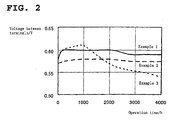
- FIG. 2 is a diagram illustrating the change with time of a voltage between terminals of the fuel cells of Examples 1, 2 and 3.
- a gas diffusion layer For both anode and cathode, as a gas diffusion layer, one comprising a carbon paper subjected to a water repellency treatment by means of PTFE (trade name: TGP-H-060M, manufactured by Toray Industries, Inc.) and a carbon layer made of carbon black and PTFE formed on the surface of the carbon paper, was used.
- PTFE trade name: TGP-H-060M, manufactured by Toray Industries, Inc.
- a carbon layer made of carbon black and PTFE formed on the surface of the carbon paper was used.
- the thickness of the carbon paper was 200 ⁇ m
- the thickness of the carbon layer was 50 ⁇ m
- An electrode/membrane assembly was prepared in the same manner as in Example 1 except that the above gas diffusion layer was used. This was incorporated into a fuel cell in the same manner as in Example 1, a continuous electricity generation was carried out in the same manner as in Example 1, and evaluation was carried out in the same manner as in Example 1. The results are shown in FIG. 2.
- Example 3 the cell voltage started to decrease after 1200 hours had passed, and it decreased from 0.61V to 0.54V after 4000 hours.
- Example 1 and 2 continuous operation properties were extremely stable, and even after 4000 hours, the cell voltage only decreased to 0.59V relative to the initial value of 0.60V in Example 1, and in Example 2, it was substantially the same as the initial value.
- a coating of a water repellency agent comprising a solvent-soluble fluorine-containing polymer can efficiently be formed on a catalyst layer and minute portions of a gas diffusion layer, whereby water repellency which lasts for a long period of time can be imparted to the entire gas diffusion electrode even if the amount of the water repellency agent is small, and accordingly an electrode/membrane assembly for a polymer electrolyte fuel cell excellent in durability can be provided.
- the solvent-soluble fluorine-containing polymer can be handled as a liquid by dissolving it in a solvent, whereby the degree of freedom in designing the electrode is high.
Landscapes
- Chemical & Material Sciences (AREA)
- General Chemical & Material Sciences (AREA)
- Electrochemistry (AREA)
- Chemical Kinetics & Catalysis (AREA)
- Manufacturing & Machinery (AREA)
- Engineering & Computer Science (AREA)
- Physics & Mathematics (AREA)
- Thermal Sciences (AREA)
- Composite Materials (AREA)
- Life Sciences & Earth Sciences (AREA)
- Sustainable Development (AREA)
- Sustainable Energy (AREA)
- Fuel Cell (AREA)
- Inert Electrodes (AREA)
Abstract
Description


Claims (8)
- An electrode/membrane assembly for a polymer electrolyte fuel cell comprising an anode, an ion exchange membrane and a cathode laminated in this order and bonded to one another, wherein the above anode and/or the above cathode is a gas diffusion electrode which comprises a gas diffusion layer comprising a porous carbon substrate and a carbon layer made of a fluororesin and carbon black formed on the substrate, and a catalyst layer disposed to be in contact with the above carbon layer, containing a catalyst and a fluorocarbon polymer having sulfonic acid groups, and which contains a solvent-soluble fluorine-containing polymer having substantially no ion exchange group, the above gas diffusion electrode is disposed so that the above catalyst layer is in contact with the above ion exchange membrane, and the above ion exchange membrane comprises a fluorocarbon polymer having sulfonic acid groups having a thickness of from 20 to 150 µm.
- The electrode/membrane assembly for a polymer electrolyte fuel cell according to Claim 1, wherein the above carbon substrate has a thickness of from 100 to 700 µm, the above carbon layer has a thickness of from 10 to 100 µm, and components of the above carbon layer infiltrate into pore portions of the above carbon substrate in a depth of from 5 to 50 µm from the surface.
- The electrode/membrane assembly for a polymer electrolyte fuel cell according to Claim 1 or 2, wherein the above carbon substrate is a carbon cloth and/or a carbon paper.
- The electrode/membrane assembly for a polymer electrolyte fuel cell according to any one of Claims 1 to 3, wherein the above solvent-soluble fluorine-containing polymer is represented by any one of the following formulae 1 to 3:
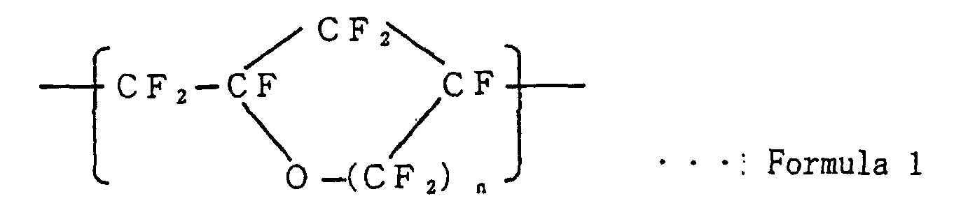
 wherein each of n, m, x and y is an integer of at least 1.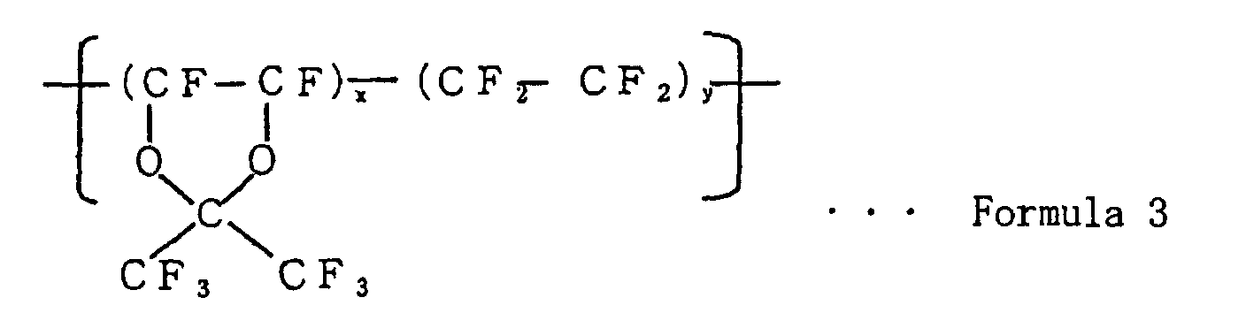
- A process for producing an electrode/membrane assembly for a polymer electrolyte fuel cell, which comprises:forming a carbon layer made of a fluororesin and carbon black on a porous carbon substrate so that components of said carbon layer infiltrate into at least part of pore portions of the above carbon substrate,coating said carbon layer with a liquid containing a catalyst and a fluorocarbon polymer having sulfonic acid groups to form a catalyst layer,followed by impregnation with a solution containing a solvent-soluble fluorine-containing polymer having substantially no ion exchange group and baking at from 100 to 200°C to prepare a gas diffusion electrode,disposing an anode and a cathode to face each other, by using the above gas diffusion electrode as the anode and/or the cathode so that the above catalyst layer faces inside, andinterposing between the anode and the cathode an ion exchange membrane comprising a fluorocarbon polymer having sulfonic acid groups having a thickness of from 20 to 150 µm, followed by hot pressing, so that the anode and the cathode are bonded to each side of the ion exchange membrane.
- The process for producing an electrode/membrane assembly for a polymer electrolyte fuel cell according to Claim 5, wherein the above solvent-soluble fluorine-containing polymer is represented by any one of the following formulae 1 to 3:
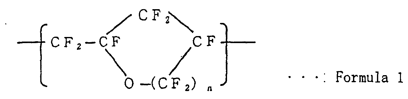
 wherein each of n, m, x and y is an integer of at least 1.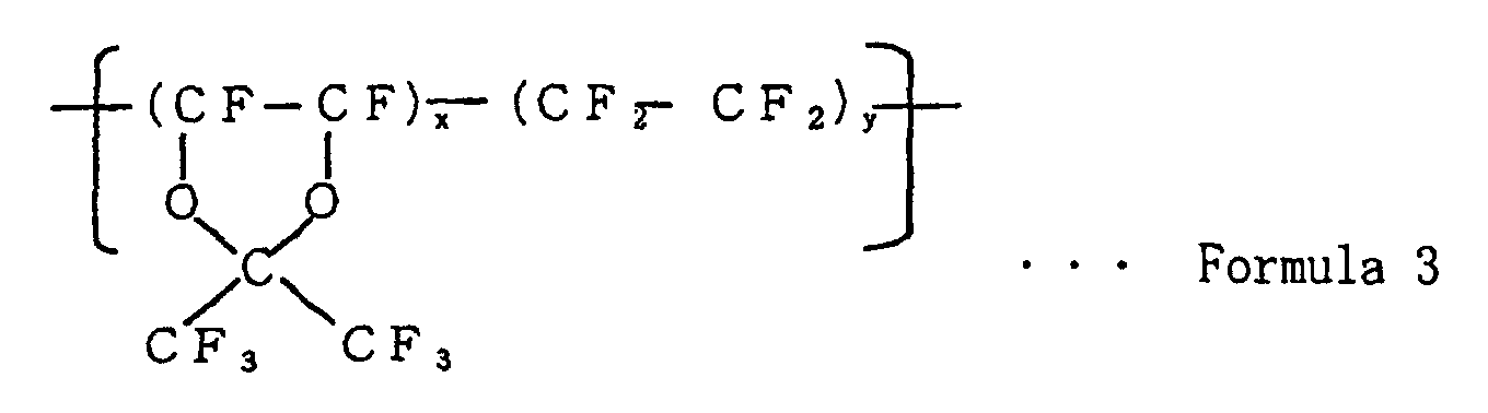
- The process for producing a polymer electrolyte fuel cell according to Claim 6,.wherein the solution containing a solvent-soluble fluorine-containing polymer has a concentration of from 0.01 to 30 mass%.
- The process for producing a polymer electrolyte fuel cell according to Claim 6 or 7, wherein the solvent of the solution containing a solvent-soluble fluorine-containing polymer is at least one member selected from the group consisting of fluoroalkanes, fluorotrialkylamines and fluoroalkyltetrahydrofurans.
Applications Claiming Priority (3)
| Application Number | Priority Date | Filing Date | Title |
|---|---|---|---|
| JP26606799 | 1999-09-20 | ||
| JP26606799 | 1999-09-20 | ||
| PCT/JP2000/006384 WO2001022510A1 (en) | 1999-09-20 | 2000-09-19 | Bonded electrode/film for solid polymer fuel cell and method for producing the same |
Publications (2)
| Publication Number | Publication Date |
|---|---|
| EP1223628A1 true EP1223628A1 (en) | 2002-07-17 |
| EP1223628A4 EP1223628A4 (en) | 2006-09-27 |
Family
ID=17425914
Family Applications (1)
| Application Number | Title | Priority Date | Filing Date |
|---|---|---|---|
| EP00961084A Withdrawn EP1223628A4 (en) | 1999-09-20 | 2000-09-19 | ELECTRODE / FILM ASSEMBLY FOR SOLID POLYMER FUEL CELL AND METHOD FOR MANUFACTURING THE SAME |
Country Status (4)
| Country | Link |
|---|---|
| US (1) | US20020098407A1 (en) |
| EP (1) | EP1223628A4 (en) |
| JP (1) | JP4852815B2 (en) |
| WO (1) | WO2001022510A1 (en) |
Cited By (1)
| Publication number | Priority date | Publication date | Assignee | Title |
|---|---|---|---|---|
| WO2005027244A3 (en) * | 2003-09-10 | 2005-11-10 | Hollingsworth & Vose Co | Fuel cell gas diffusion layer |
Families Citing this family (15)
| Publication number | Priority date | Publication date | Assignee | Title |
|---|---|---|---|---|
| JP4228643B2 (en) * | 2002-09-24 | 2009-02-25 | アイシン精機株式会社 | Method for producing membrane electrode assembly of polymer electrolyte fuel cell |
| JP4177697B2 (en) * | 2003-04-09 | 2008-11-05 | 松下電器産業株式会社 | Polymer membrane electrode assembly and polymer electrolyte fuel cell |
| JP4038453B2 (en) * | 2003-05-29 | 2008-01-23 | 大同メタル工業株式会社 | Membrane / electrode assembly for water electrolysis and water electrolyzer using the same |
| US10566669B2 (en) | 2004-02-20 | 2020-02-18 | Johnson Ip Holding, Llc | Lithium oxygen batteries having a carbon cloth current collector and method of producing same |
| US7229944B2 (en) * | 2004-07-23 | 2007-06-12 | Massachusetts Institute Of Technology | Fiber structures including catalysts and methods associated with the same |
| JP4846371B2 (en) * | 2005-01-26 | 2011-12-28 | 三星エスディアイ株式会社 | Membrane-electrode assembly for fuel cell and fuel cell system including the same |
| KR100825196B1 (en) * | 2005-03-28 | 2008-04-24 | 산요덴키가부시키가이샤 | Fuel cell |
| DE102008004164A1 (en) * | 2007-01-16 | 2008-09-25 | Dai Nippon Printing Co., Ltd. | Catalytic layered electrolyte membrane assembly, transfer sheet and method of making the same |
| JP5660879B2 (en) | 2010-12-20 | 2015-01-28 | トヨタ自動車株式会社 | Cathode side catalyst layer, membrane electrode assembly, polymer electrolyte fuel cell and method for producing the same |
| JP5530954B2 (en) * | 2011-02-21 | 2014-06-25 | 株式会社日本自動車部品総合研究所 | Fuel cell |
| WO2013049460A1 (en) * | 2011-09-28 | 2013-04-04 | Excellatron Solid State, Llc | Lithium oxygen batteries having a carbon cloth current collector and method of producing same |
| WO2015002287A1 (en) * | 2013-07-05 | 2015-01-08 | 国立大学法人九州大学 | Electrode for fuel cell and method for manufacturing same, membrane electrode assembly, and solid polymer fuel cell |
| KR102120691B1 (en) * | 2014-02-24 | 2020-06-09 | 도레이 카부시키가이샤 | Gas diffusion electrode substrate, and membrane electrode assembly and fuel cell provided therewith |
| EP3522275B1 (en) | 2016-09-29 | 2022-08-31 | Toray Industries, Inc. | Gas diffusion electrode and fuel cell |
| DE102018205571A1 (en) * | 2018-03-29 | 2019-10-02 | Siemens Aktiengesellschaft | Gas diffusion electrode, an electrolysis device and a method for operating an electrolysis system |
Family Cites Families (7)
| Publication number | Priority date | Publication date | Assignee | Title |
|---|---|---|---|---|
| JP3503193B2 (en) * | 1994-06-21 | 2004-03-02 | トヨタ自動車株式会社 | Fuel cell assembly and method of manufacturing the same |
| JPH09265992A (en) * | 1996-03-29 | 1997-10-07 | Mazda Motor Corp | Fuel cell electrode structure |
| JP3584612B2 (en) * | 1996-05-30 | 2004-11-04 | 旭硝子株式会社 | Polymer electrolyte fuel cell and method for manufacturing electrode thereof |
| JPH1012250A (en) * | 1996-06-26 | 1998-01-16 | Asahi Glass Co Ltd | Low temperature fuel cell |
| JPH10241700A (en) * | 1997-02-27 | 1998-09-11 | Toyota Central Res & Dev Lab Inc | Electrode materials for gas reaction or gas generation batteries |
| JPH1125992A (en) * | 1997-07-01 | 1999-01-29 | Tanaka Kikinzoku Kogyo Kk | Electrode for polymer solid oxide fuel cell and method for producing the same |
| JPH11354129A (en) * | 1998-06-05 | 1999-12-24 | Asahi Chem Ind Co Ltd | Electrode catalyst coating agent for fuel cell and membrane/electrode joint body using same coating agent |
-
2000
- 2000-09-19 JP JP2001525782A patent/JP4852815B2/en not_active Expired - Fee Related
- 2000-09-19 EP EP00961084A patent/EP1223628A4/en not_active Withdrawn
- 2000-09-19 WO PCT/JP2000/006384 patent/WO2001022510A1/en not_active Ceased
-
2002
- 2002-03-20 US US10/101,177 patent/US20020098407A1/en not_active Abandoned
Cited By (1)
| Publication number | Priority date | Publication date | Assignee | Title |
|---|---|---|---|---|
| WO2005027244A3 (en) * | 2003-09-10 | 2005-11-10 | Hollingsworth & Vose Co | Fuel cell gas diffusion layer |
Also Published As
| Publication number | Publication date |
|---|---|
| WO2001022510A1 (en) | 2001-03-29 |
| EP1223628A4 (en) | 2006-09-27 |
| US20020098407A1 (en) | 2002-07-25 |
| JP4852815B2 (en) | 2012-01-11 |
Similar Documents
| Publication | Publication Date | Title |
|---|---|---|
| US8007953B2 (en) | Process for producing membrane/electrode assembly for polymer electrolyte fuel cell | |
| CN1191653C (en) | Gas diffusion electrode for polymer electrolyte membrane fuel cells | |
| US6733915B2 (en) | Gas diffusion backing for fuel cells | |
| EP1615282A1 (en) | Solid polymer electrolyte membrane, membrane electrode assembly for solid polymer fuel cell, and method for producing solid polymer electrolyte membrane | |
| EP1490426B1 (en) | Ion conducting membrane having high hardness and dimensional stability | |
| US20020098407A1 (en) | Electrode/membrane assembly for a polymer electrolyte fuel cell and process for its production | |
| US20070087245A1 (en) | Multilayer polyelectrolyte membranes for fuel cells | |
| WO1998028811A1 (en) | Multiple layer membranes for fuel cells employing direct feed fuels | |
| JPH11288727A (en) | Solid high polymer fuel cell film/electrode junction body | |
| JP2009193825A (en) | Composite electrolyte membrane and method for producing the same | |
| US20110039189A1 (en) | Membrane/electrode assembly for polymer electrolyte fuel cell | |
| US20080317945A1 (en) | Electrolyte membranes for use in fuel cells | |
| JPWO2001022510A1 (en) | Electrode-membrane assembly for polymer electrolyte fuel cells and method for producing same | |
| JP3556171B2 (en) | Polymer electrolyte fuel cell and method of manufacturing the same | |
| KR102563567B1 (en) | Polymer electrolyte membrane for fuel cell and manufacturing method thereof | |
| JP2004178995A (en) | Electrolyte membrane for polymer electrolyte fuel cell and method for producing the same | |
| KR20050045878A (en) | Membrane electrode assembly, manufacturing process therefor and direct type fuel cell therewith | |
| CN114730900B (en) | Polymer electrolyte membrane, membrane-electrode assembly including the polymer electrolyte membrane, and fuel cell | |
| KR20070019868A (en) | Polymer electrolyte membrane for fuel cell, membrane-electrode assembly comprising same, fuel cell system comprising same, and method for manufacturing same | |
| EP1154505B1 (en) | Solid polymer type fuel cell and production method thereof | |
| JP4771702B2 (en) | Polymer solid electrolyte membrane with reinforcing material | |
| EP4683013A1 (en) | Polymer electrolyte membrane and membrane-electrode assembly comprising same | |
| EP1298744A1 (en) | Fuel cell | |
| JP2006269266A (en) | Composite polymer solid electrolyte membrane with reinforcing material | |
| KR20080101180A (en) | Electrolyte Membrane Improves Adhesion of Membrane-Electrode Assembly for Fuel Cell |
Legal Events
| Date | Code | Title | Description |
|---|---|---|---|
| PUAI | Public reference made under article 153(3) epc to a published international application that has entered the european phase |
Free format text: ORIGINAL CODE: 0009012 |
|
| 17P | Request for examination filed |
Effective date: 20020314 |
|
| AK | Designated contracting states |
Kind code of ref document: A1 Designated state(s): AT BE CH CY DE DK ES FI FR GB GR IE IT LI LU MC NL PT SE |
|
| A4 | Supplementary search report drawn up and despatched |
Effective date: 20060828 |
|
| RIC1 | Information provided on ipc code assigned before grant |
Ipc: H01M 8/10 20060101ALI20060822BHEP Ipc: H01M 8/02 20060101ALI20060822BHEP Ipc: H01M 4/88 20060101ALI20060822BHEP Ipc: H01M 4/96 20060101AFI20010405BHEP |
|
| 17Q | First examination report despatched |
Effective date: 20100503 |
|
| STAA | Information on the status of an ep patent application or granted ep patent |
Free format text: STATUS: THE APPLICATION IS DEEMED TO BE WITHDRAWN |
|
| 18D | Application deemed to be withdrawn |
Effective date: 20100914 |