EP1223555A2 - Image processing apparatus - Google Patents
Image processing apparatus Download PDFInfo
- Publication number
- EP1223555A2 EP1223555A2 EP02250213A EP02250213A EP1223555A2 EP 1223555 A2 EP1223555 A2 EP 1223555A2 EP 02250213 A EP02250213 A EP 02250213A EP 02250213 A EP02250213 A EP 02250213A EP 1223555 A2 EP1223555 A2 EP 1223555A2
- Authority
- EP
- European Patent Office
- Prior art keywords
- image
- value
- image processing
- images
- partial images
- Prior art date
- Legal status (The legal status is an assumption and is not a legal conclusion. Google has not performed a legal analysis and makes no representation as to the accuracy of the status listed.)
- Withdrawn
Links
Images







Classifications
-
- G—PHYSICS
- G06—COMPUTING OR CALCULATING; COUNTING
- G06T—IMAGE DATA PROCESSING OR GENERATION, IN GENERAL
- G06T5/00—Image enhancement or restoration
- G06T5/50—Image enhancement or restoration using two or more images, e.g. averaging or subtraction
Definitions
- the present invention relates to a technique for synthesizing a plurality of images into one image.
- an x-ray sensing apparatus that creates an image from the amount of x-rays that have passed through the interior of an object to be sensed (the interior of a human body, etc.)
- a device in which a spatial distribution of the intensity of the x-rays that have passed through the object to be sensed is converted directly into an electric signal by a large-sized x-ray sensor panel, and the electric signal is converted into a digital value through analog-to-digital (A/D) conversion so that the x-ray image of the object to be sensed is available to image saving, image processing, image observation or the like as a digital image.
- A/D analog-to-digital
- the object to be sensed is a chest region of a human body, and the chest region of the human body is going to be sensed with x-rays all at once
- a sensor panel that is about 40 cm ⁇ 40 cm in size.
- the x-ray sensor panel of this size is brought substantially in contact with the chest region of the human body, and x-rays are irradiated onto the x-ray sensor panel from a direction facing the human body, to thereby obtain a digital image based on the intensity distribution of the x-rays that have passed through the chest region of the human body by one x-ray sensing.
- the fine structure of the human body is going to be sensed with x-rays
- an x-ray sensor panel having pixel resolution about 0.1 to 0.2 mm.
- the x-ray sensor panel becomes very large-sized to the degree of 2000 ⁇ 2000 pixels to 4000 ⁇ 4000 pixels.
- the electric signals that are outputted from the four segment panels of the sensor panel are digitalized by the amplifiers and the A/D converters which are independent from each other, and then temporarily saved as the four segment image data.
- the four segment panels of the sensor panel are driven under control in synchronization with a timing where the x-rays are irradiated to the object to be sensed.
- data related to a variation in the gains of the respective pixels in the four segment panels of the sensor panel is stored in the memory in advance. That information is generated by irradiating the x-rays toward the sensor panel in a state where there exists no object to be sensed, and acquiring the image information.
- the fixed pattern data saved in the memory is subtracted from the four segment image data acquired in advance, and further, correction for each of the pixels is conducted due to the gain variation data.
- the gain variation data for each of the pixels is obtained by irradiating the x-rays in a state where no object to be sensed exists. For example, in a normal medical spot, since it is very difficult to acquire the gain variation data for every x-ray sensing, the gain variation data is acquired by the x-ray sensing once a day.
- the fixed pattern data is acquired at a time that is very close to the x-ray sensing time, but not at the same time as the x-ray sensing time.
- the above-mentioned time difference in the data acquirement may results in change of the environments (temperature, humidity or the like) where the data is acquired, and thus leads to the possibility that change may occur in the characteristic of the sensor panel, the amplifiers disposed for the four segments of the sensor panel, or the like.
- an image processing apparatus comprising: an image processing circuit having a first mode that corrects an offset between a first image and a second image that are adjacent to each other to synthesize the first image and the second image into a new third image, and a second mode that corrects an offset between the third image and a fourth image that are adjacent to each other to synthesize the third image and the fourth image into a new fifth image.
- an image processing method comprising the steps of: correcting an offset between a first image and a second image that are adjacent to each other to synthesize the first image and the second image into a new third image; and correcting an offset between the third image and a fourth image that are adjacent to each other to synthesize the third image and the fourth image into a new fifth image.
- a storage medium that stores program therein, the program comprising a code of a step of correcting an offset between a first image and a second image that are adjacent to each other to synthesize the first image and the second image into a new third image, and a code of a step of correcting an offset between the third image and a fourth image that are adjacent to each other to synthesize the third image and the fourth image into a new fifth image.
- an image processing apparatus comprising a correcting circuit which obtains a correction value of a step between a plurality of partial images for every partial image on the basis of statistic property of a pixel value in boundary portions between the plurality of partial images, and corrects the plurality of partial images on the basis of the correction value in order to constitute a single image from the plurality of partial images.
- an image processing method comprising the steps of: obtaining a correction value of a step between a plurality of partial images for every partial image on the basis of statistic property of a pixel value in a boundary portions between the plurality of partial images; and correcting the plurality of partial images on the basis of the correction value in order to constitute a single image from the plurality of partial images.
- a storage medium that stores program therein, the program comprising a code of a step of obtaining a correction value of a step between a plurality of partial images for every partial image on the basis of statistic property of a pixel value in a boundary portions between the plurality of partial images, and a code of a step of correcting the plurality of partial images on the basis of the correction value in order to constitute a single image from the plurality of partial images.
- the present invention is applied to, for example, an x-ray sensing apparatus 100 shown in Fig. 1.
- the x-ray sensing apparatus 100 is an apparatus that is so designed as to acquire a single image from the assembly of a plurality of segment images that are acquired by divisionally driving a sheet of sensor panel, and particularly has a function of selecting two adjacent segment images from the plurality of segment images, adjusting the offset between those segment images to form one new portion, and repeatedly executing such a process to unify these segment images into one final image in which the boundary is not visible.
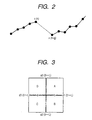
- Fig. 2 Paying attention to the one-dimensional direction of the image, it is assumed as shown in Fig. 2 that there exists a gap of g pixels between a segment image 1 and a segment image 2 adjacent to the segment image 1, and it is also assumed that the pixel value of the segment image 1 is x(0), x(1), ..., x(n), and the pixel values of the segment image 2 is x(n+g), x(n+g+1), ...
- segment image 1 and the segment image 2 are both segment images resulting from x-ray-sensing of the object to be sensed by divisionally driving a sheet of sensor panel, an error exists in the offset value between the pixel n of the segment image 1 and the pixel (n+g) of the segment image 2, and there is the possibility that the error is recognized as a step.
- the pixel n of the segment image 1 and the pixel (n+g) of the segment image 2 have a relationship that the inclination is continuous. Therefore, the average of an inclination obtained from the pixel values x(0), x(1), ..., x(n) of the segment image 1 and an inclination obtained from the pixel values x(n+g), x(n+2), ... of the segment image 2 is now defined as an inclination "K" of the object image information.
- a difference across the boundary of the pixel value x(i+p) of the segment image 1 and the pixel value x (i+p) of the segment image 2 is x(i+p) -(i).
- the inclination is the above-mentioned "K”
- an expected difference is "pK”
- a difference between the pK value and the value of x(i+p) - x(i) becomes an expected value (difference value) d of the substantial step. That is, the substantial step value d of the boundary of each of the segment images 1 and 2 is obtained by the following expression (1): d PK - x(i+P) + x(i)
- the inclination of the segment image 1 is obtained using the pixel value x(n) as a reference
- the inclination of the segment image 2 is obtained using the pixel value x(n+g) as a reference.
- the respective inclinations are averaged by using the pixel value of a point m to obtain the inclination K.
- the inclination K is represented by the following expression (2).
- differences across the boundary of the pixel value x(i+p) of the segment image 1 and the pixel value x(i) of the segment image 2 are considered as symmetry with respect to the boundary so as to be x(n+g)-x(n), x(n+g+1)-x(n-1), x(n+g+2)-x(n-2), ..., x(n+g+m)-x(n-m).
- the substantial step value d of the boundary of each of the segment images is represented by the following expression (3).
- the substantial step value d on a line that is cross one boundary can be obtained through the above-mentioned calculation process. Also, the calculation process is intensive to the calculation process of accumulative addition that makes accumulation by substantially multiplying the pixel value by a predetermined coefficient.
- a change in the pixel value with respect to the segment image (object segment image) to be processed is statistically obtained from such a step value line d(i).
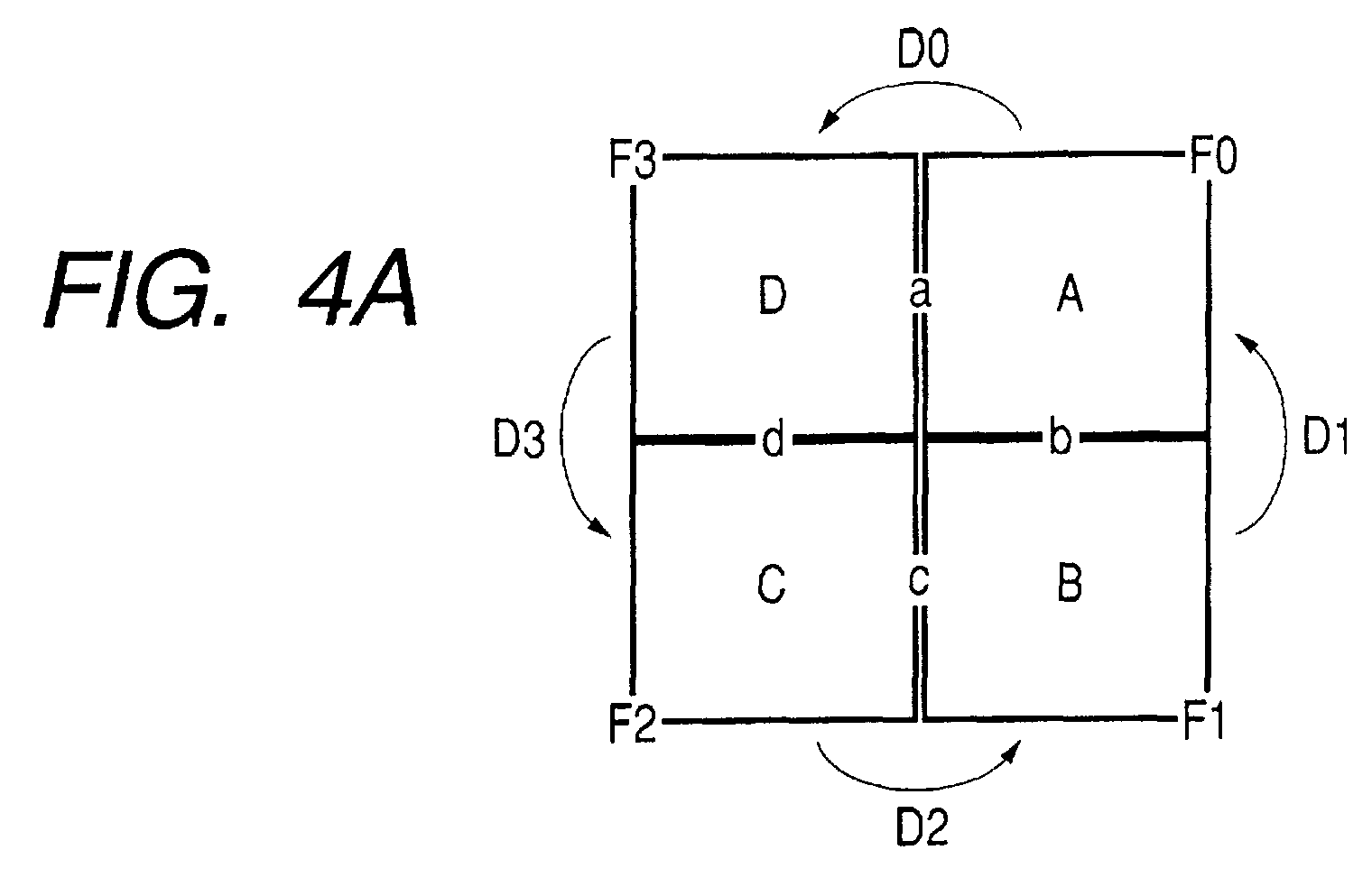
- a single sensor panel is divided into four segments and driven, as shown in Fig. 3, four segment images A, B, C and D are connected in the form of a matrix.
- the boundaries are represented by four boundaries a, b, c and d shown in Fig. 3.
- the step values obtained with the above-mentioned method are d0(0 to L-1), d1(0 to (L-1)), d2(-1 to -(L-1)) and d3(-1 to -(L-1)).
- the image center is an origin, and the position is represented by " ⁇ ".
- the step values d0(0 to L-1), d1(0 to (L-1)), d2(-1 to -(L-1)) and d3(-1 to -(L-1)) correspond to the offset value. Therefore, in this case, with the execution of the logarithmically converting process, the step values d0(0 to L-1), d1(0 to (L-1)), d2(-1 to -(L-1)) and d3(-1 to -(L-1)) correspond to a variation in the gain.
- the step values d0(0 to L-1), d1(0 to (L-1)), d2(-1 to -(L-1)) and d3(-1 to -(L-1)) at the boundaries a, b, c and d are consolidated into one certain value.
- values D0, D1, D2 and D3 are derived from the step values d0(0 to L-1), d1(0 to (L-1)), d2(-1 to -(L-1)) and d3 (-1 to - (L-1) ) one by one, respectively.
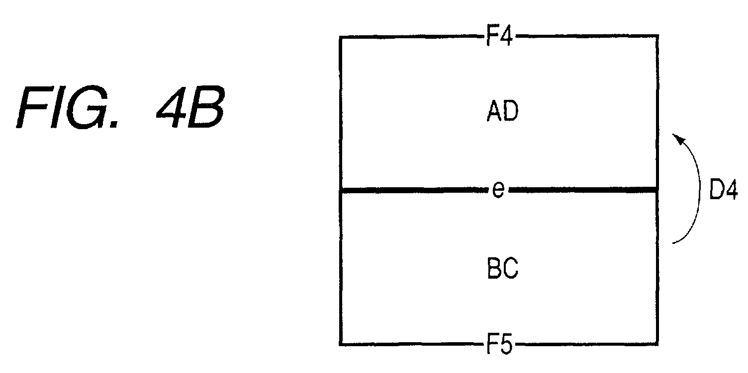
- a linear boundary is defined between the partial image AD and the partial image BC. Then, in that boundary, a step value line d4(-L to L) is newly calculated, thereby obtaining the correction value D4 as its representative value.
- the entire image is structured by the partial image AD and the partial image BC as shown in Fig. 4C.
- the inconsistency caused by only one calculation of a step value is prevented, and the partial images are synthesized without any inconsistency.
- the steps are corrected with respect to each of two partial images which are regarded as independent partial images, to constitute one new partial image, and the calculation of the step value with respect to the new partial image is repeatedly executed.
- the step value sequence are fitted by a function with a low degree of freedom, thereby being applicable to a case in which the interior of the partial images are not a constant offset error.
- the step values are shared to the respective faces such that the correction value when viewing the partial image A from the boundary a is "d0'(y)/2", and the correction value when viewing the partial image D is "-d0'(y)/2".
- the functions for correction is obtained in the above-mentioned manner to correct the partial images by adding the function values to the respective partial images. This correction enables the new partial image AD and the partial image BC to be obtained even if the offset steps of the partial images A, B, C and D are not constant within the partial images.
- the substantial step value sequence d4(-L to L) are calculated with respect to the boundary e between the new partial image AD and the partial image BC and then subjected to the function fitting, to thereby obtain the statistic step value d4'(x). Then, F4' (x,y) is added to the new partial image AD, and F5'(x,y) is added to the partial image BC, to thereby eliminate the step between the partial image AD and the partial image BC and produce one image.
- the above-mentioned process is a correcting process for the two-dimensional image, but in the correcting process, a one-dimensional function is employed.
- the boundary portion of the partial image is linear in a certain direction (x-direction or y-direction).
- the boundaries a and b shown in Fig. 3 are the boundaries of the partial image A, and even if other partial images B, C and D are coupled together so as to be regarded as a new partial image BCD as shown in Fig. 5, it is necessary to process the boundaries a and b as a series of steps. For that reason, it is necessary to fit the steps by one function or to fit the respective steps taking into consideration the bonding condition that makes two functions continuous.
- the two-dimensional function is structured by the above fitting and must be converted to a correction value to the partial image A.
- the step series different in shape is liable to be produced due to the characteristic of the sensor.
- the partial image are sequentially selected so as to prevent the shape shown in Fig. 5, and the selected partial images thus obtained are sequentially unified. Then, when two partial images are finally obtained, their boundary is made linear.
- the above process is a process for the vicinity of the boundaries a, b, c and d of the partial images A, B, C and D
- a method in which the components having the characteristic that is continuous in the boundary direction in the vicinity of the boundary are extracted with respect to the boundaries a, b, c and d, and the above characteristic components are removed in the vicinity of the boundary to make the boundaries a, b, c and d unvisible as disclosed in, for example, Japanese Patent Application Laid-open No. 2000-132663 or the like.
- Japanese Patent Application Laid-open No. 2000-132663 or the like.
- Fig. 6A schematically shows a state where attention is paid to two partial images (partial image 1 and partial image 2) among the partial images A, B, C and D, and the substantial boundary step of those partial images remain.
- reference numeral 51 denotes a section of the partial image 1
- 52 denotes a section of the partial image 2.
- Those lines 51 and 52 is provided with the moving average of some degree in the boundary direction and show the shapes of the steps.
- Fig. 6B shows a state of the boundary in the case where the components having the characteristic continuous in the boundary direction in the vicinity of the boundary are extracted with respect to the boundary of the partial image 1 and the partial image 2 to remove the characteristic components in the vicinity of the boundary so as to make the boundary unvisible through a method disclosed in Japanese Patent Application Laid-open No. 2000-132663 or the like.
- Fig. 6C shows a state where a smooth (linear in the figure) correction component is added to only W front and rear pixels of steps, as shown by "54" of Fig. 6C, and the partial image 1 and the partial image 2 are connected to each other so as to hold the fine image variation information in a direction parallel with the boundary direction.
- This step series indicated by d0(0 to L-1), d1(0 to (L-1)), d2(-1 to -(L-1)) and d3(-1 to -(L-1)) should be "0" on the average, but the steps partially remains, and an image noise is added thereto.
- the moving averages of the step series d0(0 to L-1), d1(0 to (L-1)), d2(-1 to -(L-1)) and d3(-1 to -(L-1)) are calculated, and its results are set as dm0(0 to L-1), dm1(0 to (L-1)), dm2(-1 to -(L-1)) and dm3(-1 to -(L-1)).
- C3(x,y) indicated by the following expression (16) is added to data of the partial image C:
- C3(x,y) dm3(x)(-y/W+1)/2 where x is 0 to W
- the substantial step hardly damages the image per se because the inclinations of data of the partial images A, B, C and D are taken into consideration, but if the substantial step is an extremely large value, a device may be made so as not to correct the difference.
- the above-mentioned correction of the local steps may be conducted each time when a new partial image is structured by the above-mentioned coupling of the partial images.
- the characteristic functions implemented by the x-ray sensing apparatus 100 according to this embodiment are described above. Hereinafter, the structure and operation of the x-ray sensing apparatus 100 will be described in more detail below.
- the x-ray sensing apparatus 100 includes partial panels 101a to 101d, amplifiers 102a to 102d, A/D converters 103a to 103d, DMA controllers 104a to 104d, a CPU 109, memories 105 to 108, 110 and 116, a memory unit 111 and an exposure control unit 112.
- a CPU 109, the memories 105 to 108, 110 and 116, the high-capacity memory unit 111, and the exposure control unit 112 are so connected as to communicate with each other through a bus 115.
- the CPU (central processing unit) 109 controls the operation of the entire x-ray sensing apparatus 100.
- the memory 116 stores processing program according to a flowchart of Fig. 7 therein in advance.
- the CPU 109 reads and executes the processing program from the program memory 116 to control the operation of the entire x-ray sensing apparatus 100. As a result, the operation of the x-ray sensing apparatus 100 is executed as described below.
- the exposure control unit 112 Upon radiation of x-rays onto an object 114 (a human body in this example), the exposure control unit 112 first controls an x-ray vessel so that the x-rays radiated from the x-ray vessel 113 pass through the object (human body) 114 and are inputted to each of the partial panels 101a to 101d.
- the partial panels 101a to 101d are panels divided from a sheet of sensor panel into four segments, and are driven on the basis of a timing at which the x-ray vessel 113 generates the x-rays independently (sequential driving of switching transistors not shown).
- the respective amplifiers 102a to 102d receive the electric signals outputted from the corresponding partial panels 101a to 101d, amplify and output the electric signals.
- the respective A/D converters 103a to 103d receive the electric signals outputted from the corresponding amplifiers 102a to 102d, digitalize and output the electric signals.
- the respective DMA controllers 104a to 104d store the data (partial image data) outputted from the corresponding A/D converters 103a to 103d in the memory 105(dual port memory).
- the dual port memory 105 is so structured as to read corresponding partial image data with a string of addresses through the bus 115.
- the partial image data stored in the dual port memory 105 is stored in the memory 106 (frame memory) by the CPU 109 or a DMA controller (not shown) on the bus 115.
- the partial image data thus obtained is stored in the memory 107 through the dual port memory 105 as the data of an offset-like fixed-pattern.
- x-rays are exposed toward the respective partial panels 101a to 101d by the x-ray vessel 113 in a state where no object 114 exists, and the partial image data resultantly obtained is stored in the memory 108 as the information on the gain variation for each of the pixels in the partial panels 101a to 101d.
- the CPU 109 subtracts the fixed pattern data stored in the memory 107 from the partial image data stored in the frame memory 106, and a correcting process for each pixel of the entire image using the gain variation information stored in the memory 108 is executed with respect to the subtraction result, and the correction result is stored in the memory 117.
- the above-mentioned correcting process includes a dividing process, and the dividing process may be dealt with, for example, as a subtracting process that conducts logarithmic transformation using a look up table (LUT).
- LUT look up table
- the CPU 109 stores in the memory 118 information pertaining to the position of a pixel that cannot be corrected on the basis of the gain variation information (a pixel which is a defective pixel from which no data is obtained, etc.) in the above-mentioned correcting process.
- the CPU 109 determines as a value of the defective pixel a pixel value analogized from the data of the peripheral pixels (pixels except for the defective pixels) of the pixels (defective pixels) indicated by the information stored in the memory 118 in the image data stored in the memory 117 which has been corrected. For example, the CPU 109 determines the average value of the peripheral pixels as a value of the defective pixel.
- the image data that has been subjected to the above-mentioned process is stored in the memory 110 as the image data of the object 114.
- the image data may be overwritten in the memory 117 without using the memory 110.
- the memory can be effectively employed.
- the image data may be saved in the memory unit 111 (a magnetic memory device, a large-capacity nonvolatile memory device or the like) as a file.
- the image data may be outputted to an external display device, recording device, memory device or the like by an interface (not shown).
- the partial image data obtained independently is normalized by a process using the above-mentioned data stored in the memory 107 (offset-like fixed pattern data), data (gain variation information) stored in the memory 108 or the like, and the user cannot recognize that the data is related to the partial image.
- the characteristic operation of the x-ray sensing apparatus 100 :
- Fig. 8 shows a state of the image data of the object 114 stored in the memory 110 through the above-mentioned operation.
- the data of the respective partial images A, B, C and D corresponding to the partial panels 101a to 101d is stored in the memory 110.
- a gap of g pixels (hereinafter referred to as "gap g") is defined between the images of the partial images A, B, C and D.
- the gap is a defective pixel in a sense, but in the case where the offset-like steps are produced between the respective partial images A, B, C and D, the average pixel correction is nonsense.
- the pixel is corrected with the average value.
- gap g is assumed to 1, for example.
- the substantial step value d is obtained in accordance with the above-mentioned expression (3).
- the coefficient of the pixel value x(n-2) to x(n+4) is obtained in accordance with a table shown in Fig. 9.
- a coefficient for obtaining the differentiation K at a value q and a coefficient for calculating the step value d are separated from each other, and finally summed.
- the substantial step value sequence d(i) are obtained with taking into consideration the inclination of the image data if the substantial step value d is converted into the one-dimensional data sequence that interpose the boundary x (n+1) of the partial image.
- the "i” in the above-mentioned expression (18) is an index in a direction parallel with the boundary of the partial image.
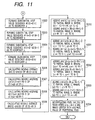
- Figs. 10 and 11 show a correcting process using the above-mentioned step value sequence d(i).
- the correcting process is implemented by executing the processing program in accordance with flowcharts shown in Figs. 10 and 11 which are stored in a program memory 116 in advance.
- Steps S301 and S302 See Fig. 10
- Step value sequence d0(0) to d0(n) of the boundary a are obtained, and the step value sequence d2(n+2) to d2(M-1) of the boundary c are obtained, through the above-mentioned expression (18).
- the pixel values are extracted across the boundary in accordance with the addresses of pixels indicated by "21” and then subjected to calculation process of the above-mentioned expression (12), to thereby obtain the difference value sequence d0(i).
- the above calculation process is executed with respect to all of the boundaries.
- the step value sequence d0(0) to d0(n) obtained in Steps S301 and S302 and the respective maximum frequency values D0, D1 of the step value sequence d2(n+2) to d2(M-1) are obtained.
- values that represent the distribution of the average values, the center values or the like may be used.
- Step S305 to Step S307
- the offset value that is added to the partial image A is set to "0", and the maximum frequency value D0 obtained in Step S303 is added to the partial image D that is opposite to the partial image A.
- the maximum frequency value D0 means the step value of the partial image D when viewed from the partial image A.
- the offset value that is added to the partial image B is set to "0", and the maximum frequency value D1 obtained in Step S304 is added to the partial image C that is opposite to the partial image B.
- the maximum frequency value D1 means the step value of the partial image C when viewed from the partial image B.
- the substantial step sequence d4(0) to d4(M-1) of the boundary e of the partial image AD and the partial image BC are prepared. Then, the maximum frequency value D2 is obtained.
- the offset value that is added to the partial image AD is set to "0"
- the step value D2 obtained in Step S312 is added to the partial image BC to unify the partial image AD and the partial image BC. Then, this result is stored in the memory 110.
- the image thus stored in the memory 110 results from conducting only the offset-like correction over the entire partial images A to D.
- the variations of the partial images A to D are not limited to the uniform offset, and there are many cases in which the above correction is insufficient.
- a process is executed in which only the vicinity of the boundaries of the image stored in the memory 110 is corrected so that a sense of incongruity that the entire image is the collection of a plurality of partial images is not given to an observer through process starting from Step S322 which will be described below.
- the correction is conducted by a method shown in Fig. 6C.
- Step S322 to Step S325 See Fig. 11
- Step S326 to Step S329
- the step value sequence d0(0) to d0(n), a1(n+2) to d1(M-1), d2(n+2) to d2(M-1), d3(0) to d3(n) obtained in Steps S322 to S325 are converted into smooth numeric sequence due to the moving average or the like. This is because the step value sequence d0(0) to d0(n), a1(n+2) to d1(M-1), d2(n+2) to d2(M-1), d3(0) to d3(n) are influenced by various noises.
- the changed origin of the above-mentioned expressions (10) and (11) is used, and dm0(y)(-x/W+1)/2, wherein x: n+1 to n+1+W, y: 0 to n, is added to the partial image A, and dm0(y)(x/W+1)/2, wherein x: n-W to n, y: 0 to n, is added to the partial image D.
- the pixels of the boundary portion that finally remains are interpolated with pixels that are not the defective pixels in the vicinity of the boundary portion.
- the region of the interpolated pixels includes a region where only one pixel does not exist in the boundary portion, that is, a region that cannot be subjected to interpolation unless correction is conducted for each of the partial images up to now.
- the above-mentioned operation is realized by programming in a calculator system, but the present invention is not limited to this structure.
- the above-mentioned operation may be realized by hardware, or may be realized by a structure that mixes hardware and program environments.
- the step value sequence is not represented by a fixed value (the maximum frequency value, the average value or the like), but the step value sequence between two partial images is fitted by a function of the low degree of freedom to prepare a step function, and the step function is divided into two and added to both of the partial images, to thereby unify two partial images.
- the step function is prepared, and the step function is divided into two and added to both of the partial images.
- the step function is added to one partial image, and a function resulting from reversing the sign of the step function is added to the other partial function.
- Figs. 13A to 13C schematically show this embodiment.
- the substantial step value sequence in the boundary region between the partial image A and the partial image B is obtained.
- a function resulting from fitting the step value sequence is divided into two, and the two step value sequences whose signs are reversed to each other are added to both of the partial image A and the partial image D so as to eliminate the step value sequence.
- the same process is conducted on the partial image B and the partial image C.
- Fig. 14 shows a process of this embodiment. This process is implemented by executing the processing program, for example, by a CPU 109 in accordance with a flowchart shown in Fig. 14 which is stored in the program memory 116 in advance. Step S401:
- the step value sequence d0(0) to d0(n) of the boundary between the partial image A and the partial image D is obtained through the above-mentioned expression (18).
- the step value sequence d2(n+2) to d2(M-1) of the boundary between the partial image B and the partial image C is obtained through the above-mentioned expression (18).
- the step value sequence d0(0) to d0(n) obtained in Step S401 is fitted by a function f0(y,p1).
- the function f0(y,p1) is a function having a parameter p1 assuming that y is the longitudinal axis of the image.
- the step value sequence d2(n+2) to d2(M-1) obtained in Step S402 is fitted by a function f2(y,p2).
- the function f2(y,p2) is a function having a parameter p2 assuming that y is the longitudinal axis of the image.
- f0(y,p1)/2 is added to the partial image A, and -f0(y,p1)/2 is added to the partial image D.
- f2(y,p2)/2 is added to the partial image B, and -f2(y,p2)/2 is added to the partial image C.
- the partial image A and the partial image D are unified into a new partial image AD, and similarly the partial image B and the partial image C are unified into a new partial image BC.
- the step value sequence d4(0) to d4(n) of the boundary between the new partial image AD and the new partial image BC is obtained through the above-mentioned expression (18).
- the step value sequence d4(0) to d4(n) obtained in Step S407 is fitted by a function f4(y,p3).
- the function f4(y,p3) is a function having a parameter p3 assuming that y is the longitudinal axis of the image.
- f4(y,p3)/2 is added to the partial image AD, and -f4(y,p3)/2 is added to the partial image BC.
- the above-mentioned process enables an appropriate correction of the step between the respective partial images A, B, C and D even if those four partial images A, B, C and D are images on which not uniform but the varied components are superimposed.
- the process shown in Fig. 11 is executed to add the repair at the step position.
- the repair in the vicinity of the boundary in this situation may be conducted every time the process shown in Fig. 14 is executed.
- the four partial panels 101a to 101d are replaced with nine partial panels to acquire nine partial images (00) to (22) as shown in Fig. 15A, and two partial images which are independent from each other are sequentially selected from those partial images (00) to (22) and combined together.
- the nine partial images (00) to (22) that are in a state shown in Fig. 15A are unified as indicated in the order of Fig. 15B, 15C, 15D and 15E.
- Fig. 15D it should be noted that when two partial images are formed, the boundary of both the partial images is linear.
- the process shown in Fig. 11 is executed to add the repair at the step position.
- the repair in the vicinity of the boundary in this situation may be conducted every time the process shown in Fig. 14 is executed.
- an image of the object 114 obtained by the x-ray sensing apparatus 100 shown in Fig. 1, that is, an image stored in the memory 110 is, for example, an image shown in Fig. 16.
- a pixel onto which the x-rays are hardly radiated or not radiated at all exists in the portion 41.
- a pixel onto which very intensive x-rays that have not passed through the object 114 are radiated exists in the portion 42 (a portion where there exists no object 114).
- a pixel onto which intermediate intensive x-rays are radiated exists in the portion 43 (a portion of the object 114).
- the output (electric signal) of the x-ray sensor panel is generally in proportion to the incident x-ray intensity, and in the energy transformation or the transforming process of the electric signal (the amplification, the impedance transformation or the like), the x-ray intensity and the linearity of the output electric signal are not always constant in the sensitive region of the sensor panel.
- the non-linearity gradually appears as approaching to the output saturation region of the electric system. Also, in the portion where the x-ray radiation is weak, the non-linearity appears due to the influence of noises, the non-stability of action at a super-low voltage of the electric circuit or the like.
- the image information on the portion where the above-mentioned non-linearity appears is nonsense information in almost all cases, and there arises no problem even if such image information normally exists.
- the offset component of the entire partial image for example, an offset in case of the image data that is in proportion to the x-rays, and a gain in case of the image data that is in proportion to the logarithm
- the offset component of the entire partial image is derived from the statistical action of a part of the partial image
- a section where the linearity is reliable is determined in the sensitive region of the sensor panels 101a to 101d in advance, and only in the case where a representative value such as the average value in the vicinity is in the reliable section before or at the same time when the substantial step value d is calculated, the step value d is used to provide the step value d in a necessary region.
- the x-ray amount is always adjusted to an optimum value, and the linearity at the portion where there exists the object information is always optimum in many cases.
- the average value m(i) of the data that interposes the boundary is obtained by the following expression (19). If the average value m(i) satisfies the following condition assuming that the minimum value is V0 and the maximum value is V1 in the reliable section, the step value d(i) obtained by the above-mentioned expression (18) is used and added to the histogram preparation. V0 ⁇ m(i) ⁇ V1
- two partial images are unified by using only the above-mentioned step value d(i). That is, in the generation of the histogram in Steps S303, S304 and S312 shown in Fig. 10, only a value obtained from the average value m(i) is used.
- an offset between two adjacent partial images selected from the plurality of partial images is corrected (adjusted) to generate one partial image where the boundary is not visible, as one new partial image into which the two partial images are unified.
- those two partial images may be corrected on the basis of the statistic property of the pixel value in the boundary portion region between the unified two partial images. This unifying process is repeatedly executed until all of the plural partial images have been unified into one new image with the result that one final image becomes an image where the boundary is not visible.
- Differences of the sixth embodiment from the first embodiment reside in a correcting method where the correction to the partial images A, B, C and D is conducted by addition/subtraction of a constant value, and the operation related to Steps S301 to S314 in the operation of the x-ray sensing apparatus 100.
- the correcting method according to the sixth embodiment will be described.
- the step values d0(0 to L-1), d1(0 to (L-1)), d2(-1 to -(L-1)) and d3(-1 to -(L-1)) at the boundaries a, b, c and d are consolidated into one certain value.
- the values D0, D1, D2 and D3 are derived from the step values d0(0 to L-1), d1(0 to (L-1)), d2 (-1 to -(L-1)) and d3(-1 to -(L-1)) one by one, respectively.
- the values D0, D1, D2 and D3 there may be applied a method of obtaining the respective average values of the step values d0(0 to L-1), d1(0 to (L-1)), d2(-1 to -(L-1)) and d3(-1 to -(L-1)) as the values D0, D1, D2 and D3.
- the step values are not averagely corrected, but a region as large as possible is corrected, for example, as shown in Fig. 17, the maximum frequency value (a peak of the histogram) is used as the values D0, D1, D2 and D3.
- D0 + D1 + D2 + D3 0
- D0 + D1 + D2 + D3 ⁇ ( ⁇ 0)
- correction values F0, F1, F2 and F3 are added to the data of the respective partial images A, B, C and D to correct the step on the boundary.
- F0 0
- F1 (D1 -D0 -D3 -D2)/2
- F2 (D1 + D2 -D0 -D3)/2
- F3 (D1 + D2 + D3 -D0)/2
- the minimum value among the correction values F0 to F3 may be added to all the values.
- Steps S301 to S321 which are the operation different from Steps S301 to S314 of the operation of the x-ray sensing apparatus 100 according to the first embodiment will be described below.
- Figs. 18 and 10 show a correcting process using the above-mentioned step value sequence d(i).
- the correcting process is implemented by executing the processing program by the CPU 109 in accordance with the flowcharts shown in Figs. 18 and 10 which are stored in the program memory 116 in advance.
- Step S301 to Step S304 See Fig. 18
- the pixel value is extracted across the boundaries in accordance with the address of a pixel indicated by "21”, and the calculation process of the above-mentioned expression (12) is conducted, to thereby obtain the step value sequence d0(i). This calculation process is executed on all of the boundaries.
- Step S305 to Step S308
- the respective maximum frequency values of d0(0) to d0(n), a1(n+2) to d1(M-1), d2(n+2) to d2(M-1), d3(0) to d3(n) obtained in Step S301 to Step S304 are obtained as D0, D1, D2 and D3.
- D0, D1, D2 and D3 for example, values that represent the distribution of the average value, the center value or the like may be employed.
- Step S313 to Step S317
- the offset values F0 to F3 obtained in Step S313 to Step S317 are added to the partial images A to D, respectively.
- the image thus stored in the memory 110 results from conducting only the offset-like correction over the partial images A to D.
- the variations of the partial images A to D are not limited to the uniform offset, but there are many cases in which the above-mentioned correction is insufficient.
- Step S322 there is executed a process in which only the vicinity of the boundaries of the image stored in the memory 110 is corrected so that a sense of incongruity that the entire image is the collection of a plurality of partial images is not given to an observer through processing starting from Step S322 which will be described below.
- a method shown in Fig. 6C is employed.
- a single image is made up of the collection of nine partial images (00), (01), (02), (10), (11), (12), (20), (21) and (22), 12 boundaries exist in partial images (00), (01), (02), (10), (11), (12), (20), (21) and (22).
- the substantial step value d is obtained in the same manner as that in the first embodiment in a direction indicated by an arrow in Fig. 19B with respect to the partial images (00), (01), (02), (10), (11), (12), (20), (21) and (22).
- the step value d is obtained, independently, and thus all of the step values d are not inconsistent. Accordingly, the correction offset values to be added to the respective partial images need to be obtained from the average value of the sum of the step values at every routes.
- the offset value F01 of a succeeding partial image (01) is obtained by averaging the offset values that pass through all of paths from the partial image (00) to the partial image (01).
- four routes indicated by a broken line in Fig. 19B are considered to cover all with the least routes.
- the offset value F01 in this case can be obtained by the following calculation process.
- F01 (d0001 + 3 ⁇ d0010 + 2 ⁇ d1020 + 2 ⁇ d2021 + d2122 - d1222 - 2 ⁇ d0212 - 2 ⁇ d0102 - d1121 - d0111)/4
- the substantial step value on the boundary portion can be statistically processed, thereby being capable of stably correcting the variations of the respective partial images. Therefore, one image excellent in image quality can be provided.
- the object of the present invention is achieved by supplying a storage medium that stores a program code of software which realizes the functions of a host computer and a terminal in accordance with the first to seventh embodiments therein to a system or a device, and reading and executing the program code stored in the storage medium by a computer (or a CPU or an MPU) in the system or the device.
- the program code per se read from the storage medium realizes the functions of the first to seventh embodiments, and the storage medium that stores the program code therein constitutes the present invention.
- the storage medium for supplying the program code there can be used a ROM, a floppy disk, a hard disk, an optical disk, an optical-magnetic disk, a CD-ROM, a CD-R, a magnetic tape, a nonvolatile memory card or the like.
- the present invention may be applied to a case in which after the program code read from the storage medium has been written into a memory of a function extension unit connected to an extension function board inserted into the computer or a function extension unit connected to the computer, a CPU disposed in the function extension board or the function extension unit, etc., conducts a part or all of the actual processing on the basis of the command of the program code, and the functions of the first to seventh embodiments are realized by that processing.
Landscapes
- Physics & Mathematics (AREA)
- General Physics & Mathematics (AREA)
- Engineering & Computer Science (AREA)
- Theoretical Computer Science (AREA)
- Image Processing (AREA)
Abstract
Description
correcting the plurality of partial images on the basis of the correction value in order to constitute a single image from the plurality of partial images.
(1) First, a substantial step value of the boundary of the segment images is acquired as follows:


In this case, four routes indicated by a broken line in Fig. 19B are considered to cover all with the least routes. The offset value F01 in this case can be obtained by the following calculation process.
Claims (35)
- An image processing apparatus, comprising:an image processing circuit having a first mode that corrects an offset between a first image and a second image that are adjacent to each other to synthesize said first image and said second image into a new third image, and a second mode that corrects an offset between said third image and a fourth image that are adjacent to each other to synthesize said third image and said fourth image into a new fifth image.
- An image processing apparatus according to claim 1, wherein said image processing circuit corrects an offset between a sixth image and a seventh image that are adjacent to each other to synthesize said sixth image and said seventh image into said fourth image.
- An image processing apparatus according to claim 1, wherein said image processing circuit corrects said two images on the basis of statistic property of a pixel value in a boundary portion region between the synthesized two images.
- An image processing apparatus according to claim 1, further comprising an image sensing element arranged to sense a plurality of images independently.
- An image processing apparatus according to claim 4, wherein said image sensing element includes a plurality of partial panels that constitute a single sensor panel.
- An image processing apparatus according to claim 5, wherein said sensor panel includes a radiation sensor panel, and wherein a pixel value that constitutes an image obtained by said radiation sensor panel is in proportion to a radiation intensity incident to said radiation sensor panel.
- An image processing apparatus according to claim 5, wherein said sensor panel includes a radiation sensor panel, and wherein a pixel value that constitutes an image obtained by said radiation sensor panel is in proportion to a logarithmic value of a radiation intensity incident to said radiation sensor panel.
- An image processing apparatus according to claim 3, wherein said image processing circuit obtains said correction value with the statistic property of the pixel value of said boundary portion region as statistic property of the substantial step value between the images, which results from subtracting a necessarily existing step value due to a tendency of the image per se from the differential value of the pixel value of the boundary portion of two images.
- An image processing apparatus according to claim 8, wherein said image processing circuit obtains said correction value with the statistic property of the substantial step value between the images as the maximum frequency value of a plurality of substantial step values obtained in association with the boundary of two images.
- An image processing apparatus according to claim 8, wherein said image processing circuit obtains said correction value with the statistic property of the substantial step value between the images as the average value of a plurality of substantial step values obtained in association with the boundary of two images.
- An image processing apparatus according to claim 8, wherein said image processing circuit obtains said correction value with the statistic property of the substantial step value between the images as a result of fitting a plurality of substantial step values obtained in association with the boundary of two images by a function of a low degree of freedom.
- An image processing apparatus according to claim 8, wherein said image processing circuit acquires the statistic property of the substantial step value between the images by using a pixel value for which the linearity of said image sensing element is ensured.
- An image processing apparatus according to claim 12, wherein said image sensing element includes a radiation sensor panel, and wherein said image processing circuit uses a pixel value within a region except for a region where no radiation is conducted to said radiation sensor panel and a region where the radiation is conducted directly to said radiation sensor panel without passing through an object, as the pixel value for which the linearity is ensured.
- An image processing apparatus according to claim 3, wherein when a substantial gap is defined in the boundary portion between said two images, said image processing circuit generates the pixel of the gap portion by interpolation after the correction.
- An image processing apparatus according to claim 3, wherein said image processing circuit locally corrects the step of said boundary portion region after the correction.
- An image processing apparatus comprising:a correcting circuit arranged to obtain a correction value of a step between a plurality of partial images for every partial image on the basis of statistic property of a pixel value in boundary portions between said plurality of partial images to correct said plurality of partial images on the basis of said correction value in order to constitute a single image from said plurality of partial images.
- An image processing apparatus according to claim 16, further comprising an image sensing element arranged to sense said plurality of partial images independently.
- An image processing apparatus according to claim 17, wherein said image sensing element includes a plurality of partial panels that constitute a single sensor panel.
- An image processing apparatus according to claim 18, wherein said sensor panel includes a radiation sensor panel, and wherein a pixel value that constitutes an image obtained by said radiation sensor panel is in proportion to a radiation intensity incident to said radiation sensor panel.
- An image processing apparatus according to claim 18, wherein said sensor panel includes a radiation sensor panel, and wherein a pixel value that constitutes an image obtained by said radiation sensor panel is in proportion to a logarithmic value of a radiation intensity incident to said radiation sensor panel.
- An image processing apparatus according to claim 16, wherein said correcting circuit obtains said correction value with the statistic property of the pixel value of said boundary portion region as statistic property of the substantial step value between the partial images, which results from subtracting a necessarily existing step value due to a tendency of the image per se from the differential value of the pixel value of the boundary portion of the partial images.
- An image processing apparatus according to claim 21, wherein said correcting circuit obtains said correction value with the statistic property of the substantial step value between the partial images as the maximum frequency value of a plurality of substantial step values obtained in association with the boundary of the partial images.
- An image processing apparatus according to claim 21, wherein said correcting circuit obtains said correction value with the statistic property of the substantial step value between the partial images as the average value of a plurality of substantial step values obtained in association with the boundary of the partial images.
- An image processing apparatus according to claim 21, wherein when said correcting circuit sets the correction value in the subjecting partial images as a reference value and obtains the correction values of other partial images, said correcting circuit obtains the statistic property of the step values between said plurality of substantial partial images from the subjecting partial images, taking into consideration the substantial step values in all of routes that reach other partial images.
- An image processing apparatus according to claim 16, wherein said correcting circuit obtains said correction value on the basis of the statistic property of the step values between a plurality of substantial partial images which are independently obtained as to a plurality of boundaries which exist in the plurality of partial images.
- An image processing apparatus according to claim 16, wherein said correcting circuit obtains the step value between said substantial partial images by using only the pixel value for which linearity is ensured in said plurality of partial images.
- An image processing apparatus according to claim 26, wherein said plurality of partial images include an image obtained by a plurality of partial panels that constitute a single radiation sensor panel, and wherein said correcting circuit obtains the substantial step value between the partial images with a pixel value of a portion except for a portion where irradiation is not conducted to said radiation sensor panel and a portion where the radiation is conducted directly to said radiation sensor panel without passing through an object, as a pixel value for which linearity is ensured.
- An image processing apparatus according to claim 16, wherein when a substantial gap is defined in the boundary portion region between said plurality of partial images, said correcting circuit generates the pixel of the gap portion by interpolation after the correction.
- An image processing apparatus according to claim 16, wherein said correcting circuit locally corrects the step of said boundary portion region after the correction.
- An image processing method, comprising the steps of:correcting an offset between a first image and a second image that are adjacent to each other to synthesize said first image and said second image into a new third image; andcorrecting an offset between said third image and a fourth image that are adjacent to each other to synthesize said third image and said fourth image into a new fifth image.
- A storage medium that stores program therein, said program comprising a code of a step of correcting an offset between a first image and a second image that are adjacent to each other to synthesize said first image and said second image into a new third image, and a code of a step of correcting an offset between said third image and a fourth image that are adjacent to each other to synthesize said third image and said fourth image into a new fifth image.
- An image processing method, comprising the steps of:obtaining a correction value of a step between a plurality of partial images for every partial image on the basis of statistic property of a pixel value in boundary portions between said plurality of partial images; andcorrecting said plurality of partial images on the basis of said correction value in order to constitute a single image from said plurality of partial images.
- A storage medium that stores program therein, said program comprising a code of a step of obtaining a correction value of a difference between a plurality of partial images for every partial images on the basis of statistic property of a pixel value in a boundary portion region between a plurality of partial images, and a code of a step of correcting said plurality of partial images on the basis of said correction value in order to constitute a single image from said plurality of partial images.
- A method according to claim 30 further comprising the steps of any one of claims 2 to 4 or claims 8 to 15.
- A method according to claim 32 further comprising the process steps of any one of claims 17 or 21 to 29.
Applications Claiming Priority (4)
| Application Number | Priority Date | Filing Date | Title |
|---|---|---|---|
| JP2001005572A JP3658324B2 (en) | 2001-01-12 | 2001-01-12 | Image processing apparatus, image processing system, image processing method, and storage medium |
| JP2001005573 | 2001-01-12 | ||
| JP2001005572 | 2001-01-12 | ||
| JP2001005573A JP3667234B2 (en) | 2001-01-12 | 2001-01-12 | Image processing apparatus, image processing system, image processing method, and storage medium |
Publications (2)
| Publication Number | Publication Date |
|---|---|
| EP1223555A2 true EP1223555A2 (en) | 2002-07-17 |
| EP1223555A3 EP1223555A3 (en) | 2003-11-05 |
Family
ID=26607634
Family Applications (1)
| Application Number | Title | Priority Date | Filing Date |
|---|---|---|---|
| EP02250213A Withdrawn EP1223555A3 (en) | 2001-01-12 | 2002-01-11 | Image processing apparatus |
Country Status (2)
| Country | Link |
|---|---|
| US (2) | US7003147B2 (en) |
| EP (1) | EP1223555A3 (en) |
Cited By (1)
| Publication number | Priority date | Publication date | Assignee | Title |
|---|---|---|---|---|
| WO2007075552A3 (en) * | 2005-12-16 | 2007-08-23 | Thomson Licensing | Imager and imaging method for digital cinematography |
Families Citing this family (19)
| Publication number | Priority date | Publication date | Assignee | Title |
|---|---|---|---|---|
| US6993183B2 (en) * | 2001-03-13 | 2006-01-31 | Canon Kabushiki Kaisha | Image processing apparatus, image processing system, image processing method, and computer-readable storage medium |
| US8285015B2 (en) * | 2002-07-05 | 2012-10-09 | Lawrence Livermore Natioonal Security, LLC | Simultaneous acquisition of differing image types |
| DE102004015876A1 (en) * | 2004-03-31 | 2005-10-27 | Siemens Ag | Method for reading a surface detector |
| JP2005304818A (en) * | 2004-04-22 | 2005-11-04 | Shimadzu Corp | Radiation imaging apparatus and radiation detection signal processing method |
| JP4708944B2 (en) * | 2005-09-26 | 2011-06-22 | キヤノン株式会社 | Image photographing apparatus and image photographing method |
| DE102006044189A1 (en) * | 2006-09-20 | 2008-04-17 | Siemens Ag | A method for providing a variety of processed image data, methods for processing a variety of image data and an X-ray image system |
| JP5523658B2 (en) * | 2007-03-23 | 2014-06-18 | 株式会社トプコン | Optical image measuring device |
| JP5229873B2 (en) * | 2008-01-31 | 2013-07-03 | 東芝メディカルシステムズ株式会社 | Image display device |
| JP5523025B2 (en) * | 2008-09-16 | 2014-06-18 | 富士フイルム株式会社 | Installation error detection method and image correction method for imaging surface of radiation image detector |
| US8872125B2 (en) | 2009-04-03 | 2014-10-28 | Lawrence Livermore National Security, Llc | Solution-grown crystals for neutron radiation detectors, and methods of solution growth |
| US8461546B2 (en) | 2009-04-03 | 2013-06-11 | Lawrence Livermore National Security, Llc | Compounds for neutron radiation detectors and systems thereof |
| JP5637816B2 (en) * | 2010-10-29 | 2014-12-10 | キヤノン株式会社 | Imaging apparatus, radiation imaging apparatus, and radiation imaging system |
| US9309456B2 (en) | 2011-04-15 | 2016-04-12 | Lawrence Livermore National Security, Llc | Plastic scintillator with effective pulse shape discrimination for neutron and gamma detection |
| US9121947B2 (en) | 2012-01-23 | 2015-09-01 | Lawrence Livermore National Security, Llc | Stress reduction for pillar filled structures |
| US8580054B2 (en) | 2012-04-04 | 2013-11-12 | Lawrence Livermore National Security, Llc | Melt-castable energetic compounds comprising oxadiazoles and methods of production thereof |
| US9650564B2 (en) | 2012-05-14 | 2017-05-16 | Lawrence Livermore National Security, Llc | System and plastic scintillator for discrimination of thermal neutron, fast neutron, and gamma radiation |
| US9274237B2 (en) | 2013-07-26 | 2016-03-01 | Lawrence Livermore National Security, Llc | Lithium-containing scintillators for thermal neutron, fast neutron, and gamma detection |
| CN106551701B (en) * | 2015-09-18 | 2020-04-10 | 上海奕瑞光电子科技股份有限公司 | Wireless flat panel detector and image correction method thereof |
| JP2024017481A (en) * | 2022-07-28 | 2024-02-08 | キヤノンメディカルシステムズ株式会社 | X-ray CT device, data collection system, data collection method, and program |
Family Cites Families (13)
| Publication number | Priority date | Publication date | Assignee | Title |
|---|---|---|---|---|
| US5181104A (en) * | 1988-05-20 | 1993-01-19 | Canon Kabushiki Kaisha | Image processing apparatus having a reader movable to a designated position |
| JPH0262671A (en) * | 1988-08-30 | 1990-03-02 | Toshiba Corp | Color editing processor |
| US5617224A (en) * | 1989-05-08 | 1997-04-01 | Canon Kabushiki Kaisha | Imae processing apparatus having mosaic processing feature that decreases image resolution without changing image size or the number of pixels |
| US6175406B1 (en) * | 1996-11-08 | 2001-01-16 | Canon Kabushiki Kaisha | Film holder and image reading apparatus |
| JPH10164437A (en) * | 1996-11-26 | 1998-06-19 | Canon Inc | Radiation imaging apparatus and radiation imaging element driving method |
| DE19718063C2 (en) | 1997-04-29 | 2001-05-17 | Rohde & Schwarz | Method for detecting and quantifying image changes in a video image that is processed with a block-based, data-reducing video code |
| JPH1155558A (en) | 1997-08-06 | 1999-02-26 | Minolta Co Ltd | Digital camera |
| JPH11234501A (en) | 1998-02-10 | 1999-08-27 | Sharp Corp | Still image synthesis method |
| US6546052B1 (en) * | 1998-05-29 | 2003-04-08 | Canon Kabushiki Kaisha | Image processing apparatus and method, and computer-readable memory |
| JP2000132663A (en) | 1998-10-23 | 2000-05-12 | Canon Inc | Image processing apparatus, method, and computer-readable storage medium |
| JP3595745B2 (en) * | 1999-01-29 | 2004-12-02 | キヤノン株式会社 | Image processing device |
| JP2002112992A (en) | 2000-06-30 | 2002-04-16 | Canon Inc | Apparatus and method for processing signal, and imaging device |
| US6993183B2 (en) | 2001-03-13 | 2006-01-31 | Canon Kabushiki Kaisha | Image processing apparatus, image processing system, image processing method, and computer-readable storage medium |
-
2002
- 2002-01-10 US US10/041,447 patent/US7003147B2/en not_active Expired - Fee Related
- 2002-01-11 EP EP02250213A patent/EP1223555A3/en not_active Withdrawn
-
2005
- 2005-11-14 US US11/271,881 patent/US7545968B2/en not_active Expired - Fee Related
Cited By (2)
| Publication number | Priority date | Publication date | Assignee | Title |
|---|---|---|---|---|
| WO2007075552A3 (en) * | 2005-12-16 | 2007-08-23 | Thomson Licensing | Imager and imaging method for digital cinematography |
| US8208047B2 (en) | 2005-12-16 | 2012-06-26 | Thomson Licensing | Imager and imaging method for digital cinematography |
Also Published As
| Publication number | Publication date |
|---|---|
| US7003147B2 (en) | 2006-02-21 |
| US7545968B2 (en) | 2009-06-09 |
| EP1223555A3 (en) | 2003-11-05 |
| US20020141255A1 (en) | 2002-10-03 |
| US20060067590A1 (en) | 2006-03-30 |
Similar Documents
| Publication | Publication Date | Title |
|---|---|---|
| EP1223555A2 (en) | Image processing apparatus | |
| EP1145568B1 (en) | Software correction of image distortion in digital cameras | |
| US6961478B2 (en) | Image processing apparatus, image processing method, and recording medium | |
| EP0021366B1 (en) | Spatial distortion correction method and apparatus for scintillation cameras | |
| US9105090B2 (en) | Wide-angle lens image correction | |
| US5336880A (en) | Process for the correction of distortions in radiological images | |
| WO2007110798A1 (en) | Temperature artifact correction | |
| US8389938B2 (en) | Method for processing images arising from a photosensitive detector and photosensitive detector | |
| EP2702450B1 (en) | System and method for correction of vignetting effect in multi-camera flat panel x-ray detectors | |
| US4538179A (en) | Image processing for unsharp masking of image | |
| US4819188A (en) | Image processing apparatus | |
| CN115825128A (en) | Wide-angle neutron photography method, device, equipment and medium with image correction function | |
| CN113096041A (en) | Image correction method and device | |
| JP3667234B2 (en) | Image processing apparatus, image processing system, image processing method, and storage medium | |
| JP3658324B2 (en) | Image processing apparatus, image processing system, image processing method, and storage medium | |
| JP4007018B2 (en) | Infrared imaging device | |
| US7417232B2 (en) | Systems and methods for camera calibration | |
| JP2000350032A (en) | Image reading method and apparatus, and storage medium | |
| JP3050396B2 (en) | Scintillation camera | |
| CN114092413B (en) | Dark field image restoration method, system, storage medium and electronic equipment | |
| JPH11134472A (en) | Image processing apparatus, computer-readable storage medium, and digital photographing apparatus | |
| CN116416188B (en) | Image processing methods, apparatus, flat panel detectors, devices and storage media | |
| JP3531256B2 (en) | Automatic correction method for variation of infrared detector | |
| JP2003126057A (en) | Image processing system | |
| JP3305749B2 (en) | Radiation image reader |
Legal Events
| Date | Code | Title | Description |
|---|---|---|---|
| PUAI | Public reference made under article 153(3) epc to a published international application that has entered the european phase |
Free format text: ORIGINAL CODE: 0009012 |
|
| AK | Designated contracting states |
Kind code of ref document: A2 Designated state(s): AT BE CH CY DE DK ES FI FR GB GR IE IT LI LU MC NL PT SE TR |
|
| AX | Request for extension of the european patent |
Free format text: AL;LT;LV;MK;RO;SI |
|
| PUAL | Search report despatched |
Free format text: ORIGINAL CODE: 0009013 |
|
| AK | Designated contracting states |
Kind code of ref document: A3 Designated state(s): AT BE CH CY DE DK ES FI FR GB GR IE IT LI LU MC NL PT SE TR |
|
| AX | Request for extension of the european patent |
Extension state: AL LT LV MK RO SI |
|
| 17P | Request for examination filed |
Effective date: 20040326 |
|
| AKX | Designation fees paid |
Designated state(s): DE FR GB IT |
|
| 17Q | First examination report despatched |
Effective date: 20040723 |
|
| 17Q | First examination report despatched |
Effective date: 20040723 |
|
| STAA | Information on the status of an ep patent application or granted ep patent |
Free format text: STATUS: THE APPLICATION HAS BEEN WITHDRAWN |
|
| 18W | Application withdrawn |
Effective date: 20160128 |