EP1223462A1 - Projector - Google Patents
Projector Download PDFInfo
- Publication number
- EP1223462A1 EP1223462A1 EP02250214A EP02250214A EP1223462A1 EP 1223462 A1 EP1223462 A1 EP 1223462A1 EP 02250214 A EP02250214 A EP 02250214A EP 02250214 A EP02250214 A EP 02250214A EP 1223462 A1 EP1223462 A1 EP 1223462A1
- Authority
- EP
- European Patent Office
- Prior art keywords
- front cover
- projector
- main body
- hinge
- projector main
- Prior art date
- Legal status (The legal status is an assumption and is not a legal conclusion. Google has not performed a legal analysis and makes no representation as to the accuracy of the status listed.)
- Granted
Links
Images





Classifications
-
- G—PHYSICS
- G03—PHOTOGRAPHY; CINEMATOGRAPHY; ANALOGOUS TECHNIQUES USING WAVES OTHER THAN OPTICAL WAVES; ELECTROGRAPHY; HOLOGRAPHY
- G03B—APPARATUS OR ARRANGEMENTS FOR TAKING PHOTOGRAPHS OR FOR PROJECTING OR VIEWING THEM; APPARATUS OR ARRANGEMENTS EMPLOYING ANALOGOUS TECHNIQUES USING WAVES OTHER THAN OPTICAL WAVES; ACCESSORIES THEREFOR
- G03B21/00—Projectors or projection-type viewers; Accessories therefor
- G03B21/14—Details
- G03B21/30—Details adapted to collapse or fold, e.g. for portability
-
- G—PHYSICS
- G03—PHOTOGRAPHY; CINEMATOGRAPHY; ANALOGOUS TECHNIQUES USING WAVES OTHER THAN OPTICAL WAVES; ELECTROGRAPHY; HOLOGRAPHY
- G03B—APPARATUS OR ARRANGEMENTS FOR TAKING PHOTOGRAPHS OR FOR PROJECTING OR VIEWING THEM; APPARATUS OR ARRANGEMENTS EMPLOYING ANALOGOUS TECHNIQUES USING WAVES OTHER THAN OPTICAL WAVES; ACCESSORIES THEREFOR
- G03B21/00—Projectors or projection-type viewers; Accessories therefor
- G03B21/005—Projectors using an electronic spatial light modulator but not peculiar thereto
- G03B21/006—Projectors using an electronic spatial light modulator but not peculiar thereto using LCD's
-
- G—PHYSICS
- G03—PHOTOGRAPHY; CINEMATOGRAPHY; ANALOGOUS TECHNIQUES USING WAVES OTHER THAN OPTICAL WAVES; ELECTROGRAPHY; HOLOGRAPHY
- G03B—APPARATUS OR ARRANGEMENTS FOR TAKING PHOTOGRAPHS OR FOR PROJECTING OR VIEWING THEM; APPARATUS OR ARRANGEMENTS EMPLOYING ANALOGOUS TECHNIQUES USING WAVES OTHER THAN OPTICAL WAVES; ACCESSORIES THEREFOR
- G03B21/00—Projectors or projection-type viewers; Accessories therefor
- G03B21/14—Details
- G03B21/145—Housing details, e.g. position adjustments thereof
Definitions
- the present invention relates to a projector for displaying an image in which picture light produced by modulating light from a light source by light valves such as a liquid crystal panel is projected on a screen by a projection lens to thereby display an image, and particularly to a projector excellent in portability such as a portable type liquid crystal projector.
- liquid crystal projector main body is constructed in the shape of a flat box, the projection lens is exposed on the front side of the projector main body, and the front side of the projection lens is opened and closed with a front cover.
- a control panel is desirably disposed on the upper side of the main body from the viewpoint of operability.
- control panel when the control panel is disposed on the upper side of the liquid crystal projector, a space for the control panel must be provided on the upper side of the main body, so that the size of the liquid crystal projector, particularly the height (thickness) of the main body, is enlarged, leading to poor portability. Furthermore, operating buttons and the like of the control panel are always exposed to the exterior, and protection thereof at the time of carrying is not sufficient, leading to possible easy breakage by collision against other things.
- the locations of the audience who see and hear the picture and voice outputted from the liquid crystal projector are arbitrary as far as they can see the picture on the screen, and, therefore, it is desired that the loudspeaker is located at an upper position in the main body of the liquid crystal projector so that the voice output is uniform in all directions.
- the loudspeaker when the loudspeaker is incorporated at an upper position in the main body of the liquid crystal projector, a surplus space for incorporating the loudspeaker is needed at an upper portion in the main body. As a result, the size of the liquid crystal projector, particularly the height (thickness) of the main body, is increased, resulting in poor portability.
- the loudspeaker when the loudspeaker is incorporated at, for example, a side face of the main body of the liquid crystal projector, the height (thickness) of the projector is not increased, but the acoustic effects (particularly, the spreading of sound) become a problem depending on the location of listening to the voice.
- the loudspeaker in order to enhance the acoustic effects, it may be contemplated to project the loudspeaker to the exterior of the main body of the liquid crystal projector and dispose the loudspeaker in a predetermined location.
- the outside surface of the liquid crystal projector has recesses and projections, resulting in that the portability of the projector is deteriorated.
- the present invention has been made in order to solve the above-mentioned problems. Accordingly, it is an object of the present invention to provide a projector such that the outside surfaces of the projector are flat at non-use times and that a control panel at a front cover can be operated at an upper portion of the projector main body at the time of using the projector.
- the projector according to the present invention comprises a roughly box-type projector main body, a projection lens exposed on the front side of the projector main body, a front cover for opening and closing the front side of the projection lens, and a left-right pair of double hinge mechanisms for turnably supporting both left and right end portions of the front cover on the projector main body, wherein the left-right pair of double hinge mechanisms comprise a pair of first and second parallel hinge pins having one-side ends supported respectively on the front cover and the projector main body, and hinge arms rectangularly connecting the other-side ends of the first and second hinge pins, and the front cover can be turned between a storage position of being roughly vertically disposed on the front side of the projector main body to cover the front side of the projection lens and an open position of being turned to an upper portion of the projector main body to open the front side of the projection lens.
- the projector according to the present invention is such that the inner side of the front cover for closing the projection lens is constructed to be a control panel.
- the front cover is turnably supported on the projector main body by the double hinge mechanisms. Therefore, the projector as a whole assumes a box type shape when the front cover is stored in the storage position for covering the front side of the projection lens.
- the hinge pins on the front cover side of the double hinge mechanisms for the front cover can be moved to positions above the upper surface of the projector main body, and the front cover can be directed to the skewly rear upper side of the projector main body.
- the inner side of the front cover for closing the projection lens is constructed to be a control panel. Therefore, it is unnecessary to provide a space for disposing the control panel at an upper portion of the main body, it is possible to secure reduction in size and protection of the control panel at the time of carrying the projector, and the control panel can be directed to the upper side of the main body and can be easily operated on the upper side of the main body at the time of using the projector.
- the projector according to the present invention is so constructed that a projection lens is exposed on the front side of a roughly box type projector main body, a loudspeaker is incorporated in a front cover for opening and closing the front side of the projection lens, and the loudspeaker is projected to the upper side of the projector main body by the movement of the front cover from a storage position for covering the front side of the projection lens to an open position on the upper side of the projector main body for opening the front side of the projection lens.
- the projector according to the present invention constituted as above can store the loudspeaker in the projector and eliminate recesses and projections at the outside surfaces of the projector at non-use times such as at the time of carrying the projector, and can project the loudspeaker to the upper side of the projector by opening the front side of the projection lens at the time of using the projector.
- the portable type liquid crystal projector is formed in a flat design not having recesses and projections at the outside surfaces, and a projection lens 2 is exposed at a position near one side of a front surface 1a of a liquid crystal projector main body 1 formed in a flat box type.
- a front cover 3 is provided which opens and closes the front side of the projection lens 2.
- the front cover 3 is used also as a control panel, and a left-right pair of loudspeakers 4 are incorporated at both left and right end positions inside of the front cover 3.
- Front end portions of both left and right side portions 1b of the liquid crystal projector main body 1 are projected to the front side in parallel, to form recessed portions 5 on the front side of the front surface la.
- the inside surface opposite to the outside surface 3a of the front cover 3 is formed to be a control panel surface 3b, and a plurality of operating buttons 6 for operating the liquid crystal projector such as a power source button, an input changeover button, an image adjustment and menu button, a menu selection and adjustment button, an adjustment end button and a reset button are disposed at a central portion of the control panel surface 3b.
- a left-right pair of sound discharging portion 7 provided with a multiplicity of sound discharging holes are disposed at both left and right positions of the control panel surface 3b, and the left-right pair of loudspeakers 4 are disposed on the inner side of the left-right pair of sound discharging portions 7.
- the front cover 3 is vertically turnably supported on the liquid crystal projector main body 1 by a left-right pair of double hinge mechanisms 11, 12 which will be described below.
- the front cover 3 can be turned in the directions of arrows a and b, namely, in vertical and forward and rearward directions in an angle range of not less than 270 ° , between a storage position of being vertically stored in the recessed portion 5 of the liquid crystal projector main body 1 so as to cover the front side of the projection lens 2, as shown in FIG. 3, and an open position of being turned to the upper side of the liquid crystal projector main body 1 to direct the control panel surface 3b and the left-right pair of loudspeakers 4 to the skewly rear upper side, as shown in FIG. 4.
- the liquid crystal projector main body 5 When the front cover 3 is vertically stored in the recessed portion 5 of the liquid crystal projector main body 5 to cover the front side of the projection lens 2, the five surfaces other than the bottom surface of the liquid crystal projector are all flat, and the liquid crystal projector is in a simple design.
- a left-right pair of double hinge mechanisms 11, 12 are connected between upper end portions of both left and right end portions 3c of the front cover 3 (the upper end positions in the condition where the front cover 3 is vertically stored in the recessed portion 5) and both left and right side portions of a front end portion 1e in an upper portion 1d of the liquid crystal projector main body 1.
- the left-right pair of double hinge mechanisms 11, 12 include first and second parallel hinge pins 13, 14 and 15, 16, and hinge arms 17, 18.
- the left-right pair of double hinge mechanisms 11, 12 are contained in a left-right pair of recessed portions 19 formed at upper end portions of the front end portions 1c at both left and right side portions 1b of the liquid crystal projector main body 1.
- the left and right pairs of hinge pins 13, 14 and 15, 16 of the left-right pair of double hinge mechanisms 11, 12 are disposed on two parallel rotation center lines.
- one-side ends 13a, 14a being the inside ends of the parallel first and second hinge pins 13, 14 present in one-side double hinge mechanism 11 are attached respectively to brackets 20, 21, which are attached to the inside of the front cover 3 and the inside of the upper portion 1d of the liquid crystal projector main body 1 by screws 22, 23, whereby the first and second hinge pins 13, 14 are attached respectively to the front cover 3 and the liquid crystal projector main body 1.
- the hinge arm 17 rectangularly connects between the other-side ends 13b, 14b being the outside ends of the first and second hinge pins 13, 14, and the other-side ends 13b, 14b of the first and second hinge pins 13, 14 are supported rotatably relative to the hinge arm 17.
- First and second torsion coil springs 24, 25 as first and second rotation energizing means are fitted over the outside peripheries of the first and second hinge pins 13, 14, and both end portions 24a, 24b and 25a, 25b of the first and second torsion coil springs 24, 25 are hooked respectively on the brackets 20, 21 and the hinge arm 17.
- the front cover 3 is turningly energized in the direction of arrow c, namely, to the upper side with the first hinge pin 13 as a center relatively to the hinge arm 17;
- the hinge arm 17 is turningly energized in the direction of e, namely, to the rear upper side with the second hinge pin 14 as a center relatively to the liquid crystal projector main body 1.
- a pair of dampers 26, 27 for giving a difference between the rotational loads of the first and second hinge pins 13, 14 are incorporated in the hinge arm 17 on the outside peripheries of the first and second hinge pins 13, 14.
- the dampers 26, 27 are, for example, composed of a cylindrical silicone rubber provided with a slit at a portion of the outside periphery thereof.
- the one-side double hinge mechanism 11 is provided with rotational angle restricting means 28, 29 for restricting the rotational angle (turning angle) of the front cover 3 in the direction of arrow c relative to the hinge arm 17 to about 270 ° and restricting the rotational angle (turning angle) of the hinge arm 17 in the direction of arrow e relative to the liquid crystal projector main body 1 to about 90° .
- the rotational angle restricting means 28, 29 include stopper pins 30, 31 projected rectangularly at portions of the outside peripheries of the hinge pins 13, 14, and stopper pin abutment portions 32, 33 formed as one body with the hinge arm 17.
- Bisected covers 34, 35 formed of a plastic or the like are attached to the outside periphery of the hinge arm 17 by screwing or the like, and a cap 36 formed of a plastic or the like is fitted over the outside peripheries of the bisected covers 34, 35, whereby the first and second hinge pins 13, 14 and the hinge arm 17 are covered.
- the other-side double hinge mechanism 12 includes first and second parallel hinge pins 15, 16 and a hinge arm 18 rectangularly connecting between them, which are integrally formed of a plastic or the like.
- the first and second hinge pins 15, 16 are formed in the shape of hollow pins, and the hinge arm 18 is also formed to be hollow.
- the first and second hinge pins 15, 16 are turnably fitted respectively to the front cover 3 and the liquid crystal projector main body 1.
- a cap 37 formed of a plastic or the like is fitted over the outside of the hinge arm 18. Therefore, a roughly U-shaped hollow portion 38 is formed over the first and second hinge pins 15, 16 and the hinge arm 18.
- the first and second hinge pins 15, 16 and the hinge arm 18 are constituted in a bisected piece structure, and the hollow portion 38 is formed by combining the bisected pieces and fixing them by screws.
- a control substrate 41 being a printed wiring board on which a plurality of control switches operated by a plurality of operating buttons 6 of the control panel described above are mounted is incorporated in a roughly central portion in the front cover 3.
- Wires 42 being a harness for electrical connection between the control substrate 41 and a main circuit substrate (not shown) in the liquid crystal projector main body 1 are passed in a roughly U-shape through the roughly U-shaped hollow portion 38 formed along the first and second hinge pins 15, 16 and the hinge arm 17 of the other-side double hinge mechanism 12.
- Both left and right end portions of the control substrate 41 and the left-right pair of loudspeakers 4 are electrically connected by two wires 43, 44, and the lengths of the two wires 43, 44 are equal, whereby a reduction in cost by common design of the left-right pair of loudspeakers 4 and the wires 43, 44 is contrived.
- the left-right pair of loudspeakers 4 are also electrically connected to the main circuit substrate (not shown) in the liquid crystal projector main body 1 by the wires 42 through the control substrate 41.
- the liquid crystal projector is provided with a mechanism whereby the front cover 3 is automatically locked when the front cover 3 is roughly vertically stored in the recessed portion 45 of the liquid crystal projector main body 1 and the lock can be released by pushing an unlocking button.
- a locking/unlocking hook portion 51 is projected, slidably in the left-right directions of arrows g, h, at one 5a of a left-right pair of opposed surfaces 5a, 5b opposite to each other from both left and right sides in the recessed portion 5 of the front surface 1a of the liquid crystal projector main body 1, and the hook portion 51 is operated in conjunction with the unlocking button 25 fitted on the front side of one side portion 1b of the liquid crystal projector main body 1.
- the hook portion 51 is slidingly energized in a locking direction of arrow g to a lock position indicated by solid lines in FIG. 11 by a locking spring (not shown), and, by pushing a pushbutton 52, the hook portion 51 can be slidingly driven in an unlocking direction of arrow h against a locking spring to an unlock position indicated by dot-dash lines in FIG. 11 through a conjunction mechanism (not shown).
- a hook portion 53 in a two streak shape or one streak shape is provided at the other opposed surface 5b of the recessed portion 5 of the liquid crystal projector main body 1, and a left-right pair of engaging portions 54, 55 being recessed portions with which the left-right pair of the hook portions 51, 53 of the liquid crystal projector main body 1 can be engaged and disengaged are provided at both left and right end faces 3c, 3d of the front cover 3.
- a slant surface 51a is provided at an upper surface of the tip end of one-side hook portion 51, and a slant surface 53a is provided particularly on the lower side of the other-side hook portion 53.
- slant surfaces 54a, 55a are provided particularly on the lower side of the outside peripheries of the left-right pair of engaging portions 54, 55. Little gaps 56 are provided between the left and right end faces 3d of the front cover 3 and the left-right pair of opposed surfaces 5a, 5b of the liquid crystal projector main body 1.
- FIGS. 1(A), 4 and 5 show the condition where the front cover 3 is roughly vertically stored at a storage position in the recessed portion 5 of the liquid crystal projector main body 1 so as to cover the front side of the projection lens 2.
- the left-right pair of hook portions 51, 53 of the liquid crystal projector main body 1 are engaged with the left-right pair of engaging portions 54, 55 of the front cover 3, and the front cover 3 is locked at the storage position in the recessed portion 5.
- the liquid crystal projector When the front cover 3 is in the stored condition, the five outside surfaces other than the bottom surface of the liquid crystal projector are all flat, the liquid crystal projector is in the condition of being small in size and high in portability, so that the liquid crystal projector can easily be carried by, for example, containing it in a bag.
- the unlocking button 52 shown in FIG. 11 is pushed, and the locking/unlocking hook portion 5a is slidingly driven in the direction of arrow h from the lock position indicated by solid lines to the unlock position indicated by dot-dash lines in FIG. 11.
- the lock of the front cover 3 in the stored position is released, and the front cover 3 is automatically turned in the direction of arrow a in FIG. 2 to the open position shown in FIG. 1(C) and FIGS. 2 and 4.
- a stopper pin abutment portion 32 of the hinge arm 17 abuts on a stopper pin 30 shown in FIG. 7 from the direction of arrow c, whereby the front cover 3 is stopped by being restricted in angle at about 90 relative to the hinge arm 17.
- a stopper pin abutment portion 33 of the hinge arm 17 abuts on a stopper pin 31 shown in FIG. 7 from the direction of arrow e, whereby the front cover 3 is stopped at the open position.
- the open condition of the front cover 3 shown in FIG. 1(C), 2 and 4 is the use condition of the liquid crystal projector where the front side of the projection lens 2 is opened and a picture can be projected onto a screen or the like by the projection lens 2.
- the operator and the audience are seated on the side of a rear surface 1f of the liquid crystal projector main body 1. Since the control panel surface 3b and the left-right pair of loudspeakers 4 of the front cover 3 are directed to the skewly rear upper side of the liquid crystal projector main body 1, the operability of the plurality of operating buttons 6 on the control panel surface 3b for the operator is-conspicuously enhanced.
- the voice generated from the left-right pair of loudspeakers 4 is directed to the skewly rear upper side of the liquid crystal projector, the voice is easy to hear for the audience seated on the side of the rear surface 1f of the liquid crystal projector main body 1, and acoustic effects are conspicuously enhanced.
- the front cover 3 is pushed in the direction of arrow b in FIG. 2.
- first the hinge arms 17, 18 of the left-right pair of double hinge mechanisms 11, 12 are turned as one body with the front cover 3 in the direction of arrow f in FIG. 7 with the left-right pair of second hinge pins 14, 16 as a center, while a spring force is charged in the second torsion coil spring 25.
- the front cover 3 is turned relative to the left-right pair of hinge arms 17, 18 in the direction of arrow d in FIG. 7 with the left-right pair of first hinge pins 13, 15 as a center, while a spring force is charged in the first torsion coil spring 24.
- the front cover 3 is returned to and stored in the storage position in the recessed portion 5 and the front side of the projection lens 2 is covered by the front cover 3, when the left-right pair of engaging portions 54, 55 are automatically engaged with the left-right pair of hook portions 51, 53 against the spring force of the lock spring and owing to guide actions of the slant surfaces 51a, 53a, 54a, 55a of these components, whereby the front cover 3 is automatically locked in the storage position.
- the projector of the present invention constituted as described above, recesses and projections at the outside surfaces of the projector are eliminated, so that the projector can be constituted in a flat design, and portability of the projector is enhanced.
- a control panel or the like can be directed skewly rearwardly upward at an upper portion of the projector main body when the front cover is opened, so that operability at the time of projection of a picture or the like is conspicuously enhanced.
- the opening and closing of the front cover can be semi-automated, and the opening and closing operations can be made to be a smooth continuous operation.
- the front cover can be stably locked in the storage position at the time of carrying the projector, the problems of chattering of the front cover and unintentional opening of the front cover due to unlocking at the time of carrying can be obviated, so that portability and safety are enhanced.
- the loudspeakers incorporated in the front panel are contained in the projector, and recesses and projections at the outside surfaces of the projector can be eliminated; at the time of use of the projector, the front side of the projection lens is opened, whereby the loudspeakers can be projected at an upper portion of the projector. Therefore, deterioration of appearance and deterioration of anti-dust property and anti-drop property as to the projector main body due to incorporation of the loudspeakers in the projector main body and exposition of a sound discharging portion provided with a multiplicity of minute holes at the outside surface of the projector main body can be obviated, and a simple appearance can be obtained.
- wirings to the loudspeakers and a substrate which are incorporated in the front panel are connected to a circuit in the projector main body by passing through a hollow portion of the hinges, so that the wirings are not exposed to the exterior and good appearance can be maintained.
Landscapes
- Physics & Mathematics (AREA)
- General Physics & Mathematics (AREA)
- Projection Apparatus (AREA)
Abstract
Description
- The present invention relates to a projector for displaying an image in which picture light produced by modulating light from a light source by light valves such as a liquid crystal panel is projected on a screen by a projection lens to thereby display an image, and particularly to a projector excellent in portability such as a portable type liquid crystal projector.
- One important factor of a portable type liquid crystal projector is smallness in size and excellent portability. For this factor, it is necessary that, in a non-use condition such as at the time of carrying the projector, recesses and projections on the outside surface of the projector are as few and little as possible so that the projector can be easily contained in a bag or the like, and that the portion where the projection lens is exposed is protected. Thus, conventionally, it is contemplated that the liquid crystal projector main body is constructed in the shape of a flat box, the projection lens is exposed on the front side of the projector main body, and the front side of the projection lens is opened and closed with a front cover.
- However, when the projection lens exposed on the front side of the liquid crystal projector main body is simply opened and closed with the front cover, the front cover becomes a projected portion on the front side at the time of carrying, resulting in an increase in size or lowering in portability of the liquid crystal projector. In addition, there is a problem as to the protection of the front cover, such as possible easy breakage of the front cover by collision on other things at the time of carrying. Besides, in a portable type liquid crystal projector, a control panel is desirably disposed on the upper side of the main body from the viewpoint of operability. However, when the control panel is disposed on the upper side of the liquid crystal projector, a space for the control panel must be provided on the upper side of the main body, so that the size of the liquid crystal projector, particularly the height (thickness) of the main body, is enlarged, leading to poor portability. Furthermore, operating buttons and the like of the control panel are always exposed to the exterior, and protection thereof at the time of carrying is not sufficient, leading to possible easy breakage by collision against other things.
- In addition, in order to make a portable type liquid crystal projector small in size and excellent in portability, it is necessary that, in a non-use condition such as at the time of carrying, recesses and projections on the outside surface of the projector are as few and little as possible so that the projector can easily be contained in a bag or the like. In a conventional liquid crystal projector, an inputted picture signal is projected onto a screen or the like and, at the same time, a voice signal is outputted as voice from a loudspeaker incorporated in the liquid crystal projector main body. In a meeting or the like, the locations of the audience who see and hear the picture and voice outputted from the liquid crystal projector are arbitrary as far as they can see the picture on the screen, and, therefore, it is desired that the loudspeaker is located at an upper position in the main body of the liquid crystal projector so that the voice output is uniform in all directions.
- However, when the loudspeaker is incorporated at an upper position in the main body of the liquid crystal projector, a surplus space for incorporating the loudspeaker is needed at an upper portion in the main body. As a result, the size of the liquid crystal projector, particularly the height (thickness) of the main body, is increased, resulting in poor portability. On the other hand, when the loudspeaker is incorporated at, for example, a side face of the main body of the liquid crystal projector, the height (thickness) of the projector is not increased, but the acoustic effects (particularly, the spreading of sound) become a problem depending on the location of listening to the voice. Taking this into account, in order to enhance the acoustic effects, it may be contemplated to project the loudspeaker to the exterior of the main body of the liquid crystal projector and dispose the loudspeaker in a predetermined location. In that case, also, the outside surface of the liquid crystal projector has recesses and projections, resulting in that the portability of the projector is deteriorated.
- The present invention has been made in order to solve the above-mentioned problems. Accordingly, it is an object of the present invention to provide a projector such that the outside surfaces of the projector are flat at non-use times and that a control panel at a front cover can be operated at an upper portion of the projector main body at the time of using the projector.
- It is another object of the present invention to provide a projector which can have both good portability of the projector and good acoustic property at the time of using the projector.
- In order to attain the above objects, the projector according to the present invention comprises a roughly box-type projector main body, a projection lens exposed on the front side of the projector main body, a front cover for opening and closing the front side of the projection lens, and a left-right pair of double hinge mechanisms for turnably supporting both left and right end portions of the front cover on the projector main body, wherein the left-right pair of double hinge mechanisms comprise a pair of first and second parallel hinge pins having one-side ends supported respectively on the front cover and the projector main body, and hinge arms rectangularly connecting the other-side ends of the first and second hinge pins, and the front cover can be turned between a storage position of being roughly vertically disposed on the front side of the projector main body to cover the front side of the projection lens and an open position of being turned to an upper portion of the projector main body to open the front side of the projection lens. In addition, the projector according to the present invention is such that the inner side of the front cover for closing the projection lens is constructed to be a control panel.
- In the projector according to the present invention constituted as above, the front cover is turnably supported on the projector main body by the double hinge mechanisms. Therefore, the projector as a whole assumes a box type shape when the front cover is stored in the storage position for covering the front side of the projection lens. In addition, when the front cover is turned from the storage position for covering the front side of the projection lens to the open position at an upper portion of the projector main body so that the front side of the projection lens is opened, the hinge pins on the front cover side of the double hinge mechanisms for the front cover can be moved to positions above the upper surface of the projector main body, and the front cover can be directed to the skewly rear upper side of the projector main body. Besides, the inner side of the front cover for closing the projection lens is constructed to be a control panel. Therefore, it is unnecessary to provide a space for disposing the control panel at an upper portion of the main body, it is possible to secure reduction in size and protection of the control panel at the time of carrying the projector, and the control panel can be directed to the upper side of the main body and can be easily operated on the upper side of the main body at the time of using the projector.
- In addition, the projector according to the present invention is so constructed that a projection lens is exposed on the front side of a roughly box type projector main body, a loudspeaker is incorporated in a front cover for opening and closing the front side of the projection lens, and the loudspeaker is projected to the upper side of the projector main body by the movement of the front cover from a storage position for covering the front side of the projection lens to an open position on the upper side of the projector main body for opening the front side of the projection lens.
- The projector according to the present invention constituted as above can store the loudspeaker in the projector and eliminate recesses and projections at the outside surfaces of the projector at non-use times such as at the time of carrying the projector, and can project the loudspeaker to the upper side of the projector by opening the front side of the projection lens at the time of using the projector.
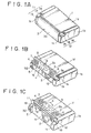
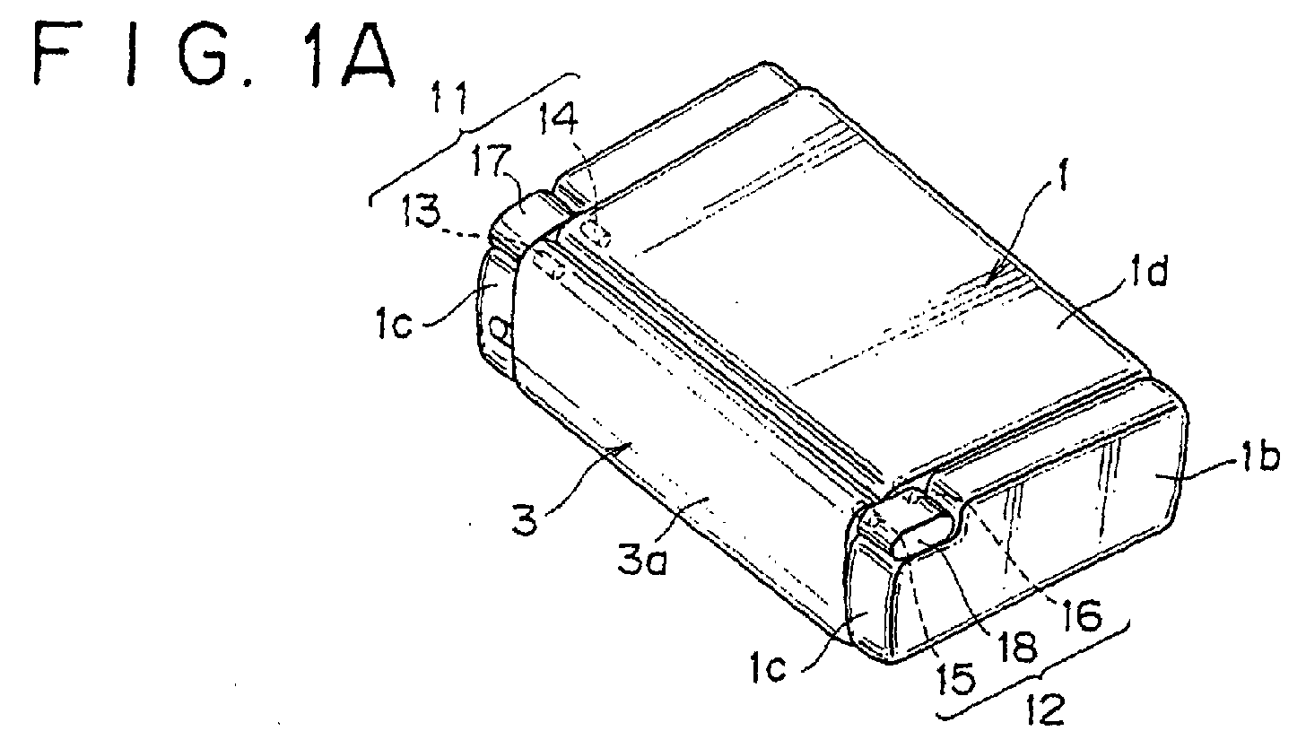
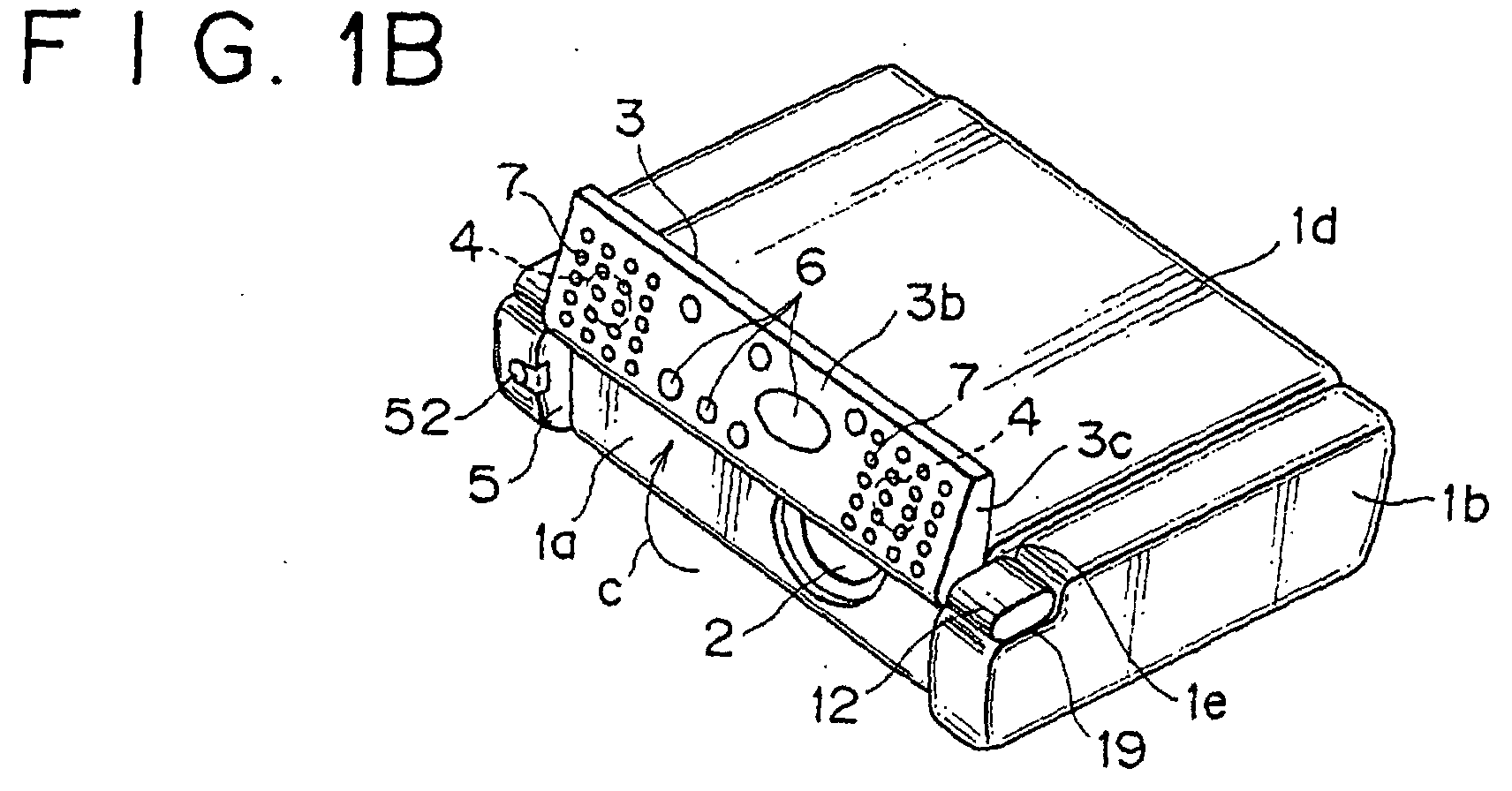
Embodiments of the invention will now be described, by way of example only, with reference to the accompanying drawings in which:- - FIG. 1A to 1C are perspective views showing the manner of opening and closing a front cover of a liquid crystal projector to which the present invention is applied;
- FIG. 2 is a side view showing the opening and closing movements of the front cover of the liquid crystal projector;
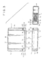
- FIG. 3 shows a plan view, a front view and a side view showing the stored condition of the front cover of the liquid crystal projector;
- FIG. 4 shows a plan view, a front view and a side view showing the opened condition of the front cover of the liquid crystal projector;
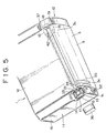
- FIG. 5 is a partly exploded perspective view of one of double hinge mechanisms of the liquid crystal projector;
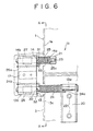
- FIG. 6 is a plan view illustrating the double hinge mechanism;
- FIG. 7 is a sectional view taken along line A-A of FIG. 6;
- FIG. 8 is a partly exploded perspective view showing the condition of passing a wire through the other double hinge mechanism;
- FIG. 9 is a perspective view illustrating the wiring in the front cover of the liquid crystal projector;
- FIG. 10A and 10B are perspective views illustrating a lock mechanism of the front cover of the liquid crystal projector; and
- FIG. 11 is a partly broken front view illustrating a locking/unlocking mechanism of the front cover.
-
- Now, embodiments of a liquid crystal projector to which the present invention is applied will be described below in the following order.
- (1) Description of an opening and closing mechanism
of a front cover incorporating a loudspeaker and used
also as a control panel (FIGS. 1 to 11);
- (1-1) Description of double hinge mechanisms (FIGS. 1 to 7) ;
- (1-2) Description of a wiring structure of wires for the loudspeakers (FIGS. 8 and 9);
- (1-3) Description of a locking/unlocking means for the front cover (FIGS. 9 to 11);
- (1-4) Description of opening and closing operations of the front cover (FIGS. 1 to 11).
-
- First, as shown in FIGS. 1 to 11, the portable type liquid crystal projector is formed in a flat design not having recesses and projections at the outside surfaces, and a
projection lens 2 is exposed at a position near one side of afront surface 1a of a liquid crystal projectormain body 1 formed in a flat box type. Afront cover 3 is provided which opens and closes the front side of theprojection lens 2. Thefront cover 3 is used also as a control panel, and a left-right pair ofloudspeakers 4 are incorporated at both left and right end positions inside of thefront cover 3. Front end portions of both left andright side portions 1b of the liquid crystal projectormain body 1 are projected to the front side in parallel, to formrecessed portions 5 on the front side of the front surface la. The inside surface opposite to theoutside surface 3a of thefront cover 3 is formed to be acontrol panel surface 3b, and a plurality ofoperating buttons 6 for operating the liquid crystal projector such as a power source button, an input changeover button, an image adjustment and menu button, a menu selection and adjustment button, an adjustment end button and a reset button are disposed at a central portion of thecontrol panel surface 3b. A left-right pair ofsound discharging portion 7 provided with a multiplicity of sound discharging holes are disposed at both left and right positions of thecontrol panel surface 3b, and the left-right pair ofloudspeakers 4 are disposed on the inner side of the left-right pair of sounddischarging portions 7. - The
front cover 3 is vertically turnably supported on the liquid crystal projectormain body 1 by a left-right pair ofdouble hinge mechanisms front cover 3 can be turned in the directions of arrows a and b, namely, in vertical and forward and rearward directions in an angle range of not less than 270 ° , between a storage position of being vertically stored in therecessed portion 5 of the liquid crystal projectormain body 1 so as to cover the front side of theprojection lens 2, as shown in FIG. 3, and an open position of being turned to the upper side of the liquid crystal projectormain body 1 to direct thecontrol panel surface 3b and the left-right pair ofloudspeakers 4 to the skewly rear upper side, as shown in FIG. 4. When thefront cover 3 is vertically stored in therecessed portion 5 of the liquid crystal projectormain body 5 to cover the front side of theprojection lens 2, the five surfaces other than the bottom surface of the liquid crystal projector are all flat, and the liquid crystal projector is in a simple design. - Next, as shown in FIGS. 1 to 7, a left-right pair of
double hinge mechanisms right end portions 3c of the front cover 3 (the upper end positions in the condition where thefront cover 3 is vertically stored in the recessed portion 5) and both left and right side portions of afront end portion 1e in anupper portion 1d of the liquid crystal projectormain body 1. The left-right pair ofdouble hinge mechanisms parallel hinge pins arms double hinge mechanisms portions 19 formed at upper end portions of thefront end portions 1c at both left andright side portions 1b of the liquid crystal projectormain body 1. The left and right pairs ofhinge pins double hinge mechanisms - As shown in FIGS. 5 and 6, one-side ends 13a, 14a being the inside ends of the parallel first and
second hinge pins double hinge mechanism 11 are attached respectively tobrackets front cover 3 and the inside of theupper portion 1d of the liquid crystal projectormain body 1 byscrews second hinge pins front cover 3 and the liquid crystal projectormain body 1. Thehinge arm 17 rectangularly connects between the other-side ends 13b, 14b being the outside ends of the first and second hinge pins 13, 14, and the other-side ends 13b, 14b of the first and second hinge pins 13, 14 are supported rotatably relative to thehinge arm 17. - First and second torsion coil springs 24, 25 as first and second rotation energizing means are fitted over the outside peripheries of the first and second hinge pins 13, 14, and both
end portions brackets hinge arm 17. By the firsttorsion coil spring 24, thefront cover 3 is turningly energized in the direction of arrow c, namely, to the upper side with thefirst hinge pin 13 as a center relatively to thehinge arm 17; by the secondtorsion coil spring 25, thehinge arm 17 is turningly energized in the direction of e, namely, to the rear upper side with thesecond hinge pin 14 as a center relatively to the liquid crystal projectormain body 1. - In order that a first rotation mode of rotating the
front cover 3 in the direction of arrow c with thefirst hinge pin 13 as a center is first carried out and subsequently a second rotation mode of rotating thefront cover 3 in the direction of arrow e with thesecond hinge pin 14 as a center is carried out at the time of opening thefront cover 3 described later, a pair ofdampers hinge arm 17 on the outside peripheries of the first and second hinge pins 13, 14. Thedampers - The one-side
double hinge mechanism 11 is provided with rotationalangle restricting means front cover 3 in the direction of arrow c relative to thehinge arm 17 to about 270 ° and restricting the rotational angle (turning angle) of thehinge arm 17 in the direction of arrow e relative to the liquid crystal projectormain body 1 to about 90° . The rotationalangle restricting means pin abutment portions hinge arm 17. Bisected covers 34, 35 formed of a plastic or the like are attached to the outside periphery of thehinge arm 17 by screwing or the like, and acap 36 formed of a plastic or the like is fitted over the outside peripheries of the bisected covers 34, 35, whereby the first and second hinge pins 13, 14 and thehinge arm 17 are covered. - Next, the other-side
double hinge mechanism 12 includes first and second parallel hinge pins 15, 16 and ahinge arm 18 rectangularly connecting between them, which are integrally formed of a plastic or the like. The first and second hinge pins 15, 16 are formed in the shape of hollow pins, and thehinge arm 18 is also formed to be hollow. The first and second hinge pins 15, 16 are turnably fitted respectively to thefront cover 3 and the liquid crystal projectormain body 1. Acap 37 formed of a plastic or the like is fitted over the outside of thehinge arm 18. Therefore, a roughly U-shapedhollow portion 38 is formed over the first and second hinge pins 15, 16 and thehinge arm 18. The first and second hinge pins 15, 16 and thehinge arm 18 are constituted in a bisected piece structure, and thehollow portion 38 is formed by combining the bisected pieces and fixing them by screws. - Next, as shown in FIGS. 8 and 9, a
control substrate 41 being a printed wiring board on which a plurality of control switches operated by a plurality ofoperating buttons 6 of the control panel described above are mounted is incorporated in a roughly central portion in thefront cover 3.Wires 42 being a harness for electrical connection between thecontrol substrate 41 and a main circuit substrate (not shown) in the liquid crystal projectormain body 1 are passed in a roughly U-shape through the roughly U-shapedhollow portion 38 formed along the first and second hinge pins 15, 16 and thehinge arm 17 of the other-sidedouble hinge mechanism 12. Both left and right end portions of thecontrol substrate 41 and the left-right pair ofloudspeakers 4 are electrically connected by twowires wires loudspeakers 4 and thewires loudspeakers 4 are also electrically connected to the main circuit substrate (not shown) in the liquid crystal projectormain body 1 by thewires 42 through thecontrol substrate 41. - Next, as shown in FIGS. 9 to 11, the liquid crystal projector is provided with a mechanism whereby the
front cover 3 is automatically locked when thefront cover 3 is roughly vertically stored in the recessed portion 45 of the liquid crystal projectormain body 1 and the lock can be released by pushing an unlocking button. In this case, a locking/unlockinghook portion 51 is projected, slidably in the left-right directions of arrows g, h, at one 5a of a left-right pair ofopposed surfaces portion 5 of thefront surface 1a of the liquid crystal projectormain body 1, and thehook portion 51 is operated in conjunction with the unlockingbutton 25 fitted on the front side of oneside portion 1b of the liquid crystal projectormain body 1. Namely, thehook portion 51 is slidingly energized in a locking direction of arrow g to a lock position indicated by solid lines in FIG. 11 by a locking spring (not shown), and, by pushing apushbutton 52, thehook portion 51 can be slidingly driven in an unlocking direction of arrow h against a locking spring to an unlock position indicated by dot-dash lines in FIG. 11 through a conjunction mechanism (not shown). - A
hook portion 53 in a two streak shape or one streak shape is provided at the otheropposed surface 5b of the recessedportion 5 of the liquid crystal projectormain body 1, and a left-right pair of engagingportions hook portions main body 1 can be engaged and disengaged are provided at both left and right end faces 3c, 3d of thefront cover 3. Aslant surface 51a is provided at an upper surface of the tip end of one-side hook portion 51, and aslant surface 53a is provided particularly on the lower side of the other-side hook portion 53. Also, slant surfaces 54a, 55a are provided particularly on the lower side of the outside peripheries of the left-right pair of engagingportions Little gaps 56 are provided between the left and right end faces 3d of thefront cover 3 and the left-right pair ofopposed surfaces main body 1. - Next, opening and closing operations of the
front cover 3 will be described referring to FIGS. 1 to 11. First, FIGS. 1(A), 4 and 5 show the condition where thefront cover 3 is roughly vertically stored at a storage position in the recessedportion 5 of the liquid crystal projectormain body 1 so as to cover the front side of theprojection lens 2. At this time, as shown in FIG. 11, the left-right pair ofhook portions main body 1 are engaged with the left-right pair of engagingportions front cover 3, and thefront cover 3 is locked at the storage position in the recessedportion 5. When thefront cover 3 is in the stored condition, the five outside surfaces other than the bottom surface of the liquid crystal projector are all flat, the liquid crystal projector is in the condition of being small in size and high in portability, so that the liquid crystal projector can easily be carried by, for example, containing it in a bag. - Next, at the time of opening the
front cover 3 to an upper portion of the liquid crystal projectormain body 1, the unlockingbutton 52 shown in FIG. 11 is pushed, and the locking/unlockinghook portion 5a is slidingly driven in the direction of arrow h from the lock position indicated by solid lines to the unlock position indicated by dot-dash lines in FIG. 11. By this, the lock of thefront cover 3 in the stored position is released, and thefront cover 3 is automatically turned in the direction of arrow a in FIG. 2 to the open position shown in FIG. 1(C) and FIGS. 2 and 4. - In this case, in the condition where the left-right pair of
hinge arms portions 19 as shown in FIGS. 1(B) and 3 due to the rotational load exerted by thedamper 27 at the outside periphery of thesecond hinge pin 14 of the one-sidedouble hinge mechanism 11, thefront cover 3 is rotated by roughly 180 in the direction of arrow c relatively to the left-right pair ofhinge arms double hinge mechanisms portion 5 to a half-open position shown in FIG. 1(B) by the spring force charged in the firsttorsion coil spring 24 at the outside periphery of thefirst hinge pin 13, resulting in that thefront cover 3 rises up roughly vertically to the upper side. At this time, a stopperpin abutment portion 32 of thehinge arm 17 abuts on astopper pin 30 shown in FIG. 7 from the direction of arrow c, whereby thefront cover 3 is stopped by being restricted in angle at about 90 relative to thehinge arm 17. - The moment the stopper
pin abutment portion 32 abuts on thestopper pin 30 from the direction of arrow c, a rotational force in the direction of arrow e with thesecond hinge pin 14 as a center is subsequently exerted on thehinge arm 17 by the spring force charged in the secondtorsion coil spring 25 at the outside periphery of thesecond hinge pin 14. By this, the left-right pair ofhinge arms double hinge mechanisms front cover 3 is subsequently turned automatically in the direction of arrow e from the half-open position shown in FIG. 1(B) to the open position at an upper portion of the liquid crystal projectormain body 1 shown in FIGS. 1(C), 2 and 4. Then, a stopperpin abutment portion 33 of thehinge arm 17 abuts on astopper pin 31 shown in FIG. 7 from the direction of arrow e, whereby thefront cover 3 is stopped at the open position. - Then, with the
front cover 3 rotated in the direction of arrow e to the open position at the upper portion of the liquid crystal projectormain body 1, the left-right pair ofhinge arms double hinge mechanisms front cover 3 are raised to positions higher than theupper portion 1d of the liquid crystal projectormain body 1, whereby thecontrol panel surface 3b and the left-right pair ofloudspeakers 4 turned up of thefront cover 3 are directed to the skewly rear upper side of the liquid crystal projectormain body 1. - The open condition of the
front cover 3 shown in FIG. 1(C), 2 and 4 is the use condition of the liquid crystal projector where the front side of theprojection lens 2 is opened and a picture can be projected onto a screen or the like by theprojection lens 2. In the use condition of the liquid crystal projector, the operator and the audience are seated on the side of arear surface 1f of the liquid crystal projectormain body 1. Since thecontrol panel surface 3b and the left-right pair ofloudspeakers 4 of thefront cover 3 are directed to the skewly rear upper side of the liquid crystal projectormain body 1, the operability of the plurality ofoperating buttons 6 on thecontrol panel surface 3b for the operator is-conspicuously enhanced. In addition, since the voice generated from the left-right pair ofloudspeakers 4 is directed to the skewly rear upper side of the liquid crystal projector, the voice is easy to hear for the audience seated on the side of therear surface 1f of the liquid crystal projectormain body 1, and acoustic effects are conspicuously enhanced. - At the time of returning the
front cover 3 from the open position to the storage position, thefront cover 3 is pushed in the direction of arrow b in FIG. 2. At this time, in reverse operation to that at the time of opening, first thehinge arms double hinge mechanisms front cover 3 in the direction of arrow f in FIG. 7 with the left-right pair of second hinge pins 14, 16 as a center, while a spring force is charged in the secondtorsion coil spring 25. Subsequently, thefront cover 3 is turned relative to the left-right pair ofhinge arms torsion coil spring 24. - Then, as shown in FIG. 11, the
front cover 3 is returned to and stored in the storage position in the recessedportion 5 and the front side of theprojection lens 2 is covered by thefront cover 3, when the left-right pair of engagingportions hook portions front cover 3 is automatically locked in the storage position. - According to the projector of the present invention constituted as described above, recesses and projections at the outside surfaces of the projector are eliminated, so that the projector can be constituted in a flat design, and portability of the projector is enhanced. A control panel or the like can be directed skewly rearwardly upward at an upper portion of the projector main body when the front cover is opened, so that operability at the time of projection of a picture or the like is conspicuously enhanced. The opening and closing of the front cover can be semi-automated, and the opening and closing operations can be made to be a smooth continuous operation. In addition, since the front cover can be stably locked in the storage position at the time of carrying the projector, the problems of chattering of the front cover and unintentional opening of the front cover due to unlocking at the time of carrying can be obviated, so that portability and safety are enhanced.
- Besides, at non-use times such as at the time of carrying, the loudspeakers incorporated in the front panel are contained in the projector, and recesses and projections at the outside surfaces of the projector can be eliminated; at the time of use of the projector, the front side of the projection lens is opened, whereby the loudspeakers can be projected at an upper portion of the projector. Therefore, deterioration of appearance and deterioration of anti-dust property and anti-drop property as to the projector main body due to incorporation of the loudspeakers in the projector main body and exposition of a sound discharging portion provided with a multiplicity of minute holes at the outside surface of the projector main body can be obviated, and a simple appearance can be obtained. In addition, acoustic effects at the time of projecting a picture are enhanced. Besides, wirings to the loudspeakers and a substrate which are incorporated in the front panel are connected to a circuit in the projector main body by passing through a hollow portion of the hinges, so that the wirings are not exposed to the exterior and good appearance can be maintained.
- While the invention has been described with reference to specific embodiment chosen for purpose of illustration, it should be apparent that numerous modifications could be made thereto by those skilled in the art without departing from the basic concept and scope of the invention.
Claims (13)
- A projector comprising:wherein said left-right pair of double hinge mechanisms comprise:a roughly box-like projector main body;a projection lens exposed on the front side of said projector main body;a front cover for opening and closing the front side of said projection lens; anda left-right pair of double hinge mechanisms for turnably supporting both left and right end portions of said front cover on said projector main body,two pairs of hinge pins, each pair comprising first and second parallel hinge pins, one end of each first hinge pin being supported on said front cover and one end of each second hinge pin being supported on said projector main body; anda hinge arm for each pair of hinge pins, perpendicularly connecting the other ends of said first and second hinge pins,said front cover being turnable between a storage position of being roughly vertically disposed on the front side of said projector main body to cover the front side of said projection lens and an open position of being turned to an upper portion of said projector main body to open the front side of said projection lens.
- A projector as set forth in claim 1, wherein said storage position of said front cover is formed in a recessed portion provided on the front side of said projector main body, and said front cover is stored by being disposed in said recessed portion.
- A projector as set forth in claim 1 or 2, wherein the inner side of said front cover for closing said projection lens is constructed to be a control panel.
- A projector as set forth in claim 3, wherein the surface of said control panel of said front cover is inclined to be directed slanted rearwardly upward when said front cover is turned to the open position at said upper portion of said projector main body.
- A projector according to any one of the preceding claims, further comprising:a means for locking and unlocking said front cover at said storage position;a first rotation energizing means for turningly energizing said front cover to the upper side relative to said hinge arms; anda second rotation energizing means for turningly energizing said front cover to the rear upward side relative to said hinge arms,said first and second rotation energizing means disposed respectively at the outer peripheries of said first and second hinge pins of one of said double hinge mechanisms.
- A projector as set forth in claim 5, wherein said one of said double hinge mechanisms comprises:a first rotation mode in which said front cover is rotated upward by about 180° with said first hinge pin as a center by said first rotation energizing means, through unlocking of said front cover at said storage position; anda second rotation mode in which, after the end of said first rotation mode, said front cover is rotated to the rear side by about 90° with said second hinge pin as a center by said second rotation energizing means.
- A projector as set forth in claim 5 or 6, wherein said one of said double hinge mechanisms comprises a pair of dampers different in rotational load for performing said first rotation mode and said second rotation mode.
- A projector as set forth in claim 5, 6 or 7, wherein said first and second rotation energizing means are each composed of a torsion coil spring.
- A projector as set forth in claim 5, 6 , 7 or 8, wherein said storage position of said front cover is. formed in a recessed portion provided at the front side of said projector main body, said front cover is stored by being vertically disposed in said recessed portion, a left-right pair of opposite surfaces in said recessed portion opposed to left and right end faces of said front cover are provided with a left-right pair of hook portions, said left and right end faces of said front cover are provided with engaging portions for engagement with said left-right pair of hook portions, and one of said left-right pair of hook portions is constructed to be said locking and unlocking means.
- A projector comprising:a roughly box-like projector main body;a projection lens exposed on the front side of said projector main body;a front cover for opening and closing the front side of said projection lens; anda loudspeaker incorporated in said front cover and projected to an upper portion of said projector main body when said front cover is moved from a storage position in which said front cover covers the front side of said projection lens to an open position in which said front cover is moved to an upper portion of said projector main body to open the front side of said projection lens.
- A projector as set forth in claim 10, wherein said loudspeaker is directed slanted rearwardly upwards when said front cover is moved to said open position at the upper portion of said projector main body.
- A projector as set forth in claim 10 or 11, wherein a hinge mechanism is provided for turning said front cover relative to said projector main body between said storage position and said open position, and said loudspeaker is disposed on the inner side of said front cover for closing said projection lens so that said loudspeaker is directed to the upper side or the skewly rear upper side of said projector main body when said front cover is rotated from said storage position to said open position by said hinge mechanism and said inner side of said front cover is directed upwards or skewly rearwardly upwards.
- A projector as set forth in claim 12, wherein said hinge mechanism is provided with a hollow hinge pin, and a wiring for connection between a circuit in said projector main body and said loudspeaker and/or a control panel substrate incorporated in said front cover is passed through said hollow hinge pin.
Applications Claiming Priority (4)
| Application Number | Priority Date | Filing Date | Title |
|---|---|---|---|
| JP2001005313 | 2001-01-12 | ||
| JP2001005318A JP2002214698A (en) | 2001-01-12 | 2001-01-12 | projector |
| JP2001005313A JP2002214709A (en) | 2001-01-12 | 2001-01-12 | projector |
| JP2001005318 | 2001-01-12 |
Publications (2)
| Publication Number | Publication Date |
|---|---|
| EP1223462A1 true EP1223462A1 (en) | 2002-07-17 |
| EP1223462B1 EP1223462B1 (en) | 2006-03-22 |
Family
ID=26607621
Family Applications (1)
| Application Number | Title | Priority Date | Filing Date |
|---|---|---|---|
| EP02250214A Expired - Lifetime EP1223462B1 (en) | 2001-01-12 | 2002-01-11 | Projector |
Country Status (3)
| Country | Link |
|---|---|
| US (1) | US6726336B2 (en) |
| EP (1) | EP1223462B1 (en) |
| DE (1) | DE60210008T2 (en) |
Cited By (3)
| Publication number | Priority date | Publication date | Assignee | Title |
|---|---|---|---|---|
| WO2006087831A1 (en) | 2005-02-18 | 2006-08-24 | Mitsubishi Denki Kabushiki Kaisha | Projection display device |
| TWI450023B (en) * | 2013-03-13 | 2014-08-21 | Acer Inc | Projector and projector setting method |
| CN105159016A (en) * | 2015-10-30 | 2015-12-16 | 广西中才铝业有限公司 | Projector shell |
Families Citing this family (16)
| Publication number | Priority date | Publication date | Assignee | Title |
|---|---|---|---|---|
| US7108382B2 (en) * | 2003-07-08 | 2006-09-19 | Hewlett-Packard Development Company, L.P. | Digital projector access panel |
| JP2005055812A (en) * | 2003-08-07 | 2005-03-03 | Olympus Corp | Projector device and desk having the projector device fitted therein |
| US7222395B2 (en) * | 2003-11-12 | 2007-05-29 | Toshiba International Corporation | Incremental locking hinge assembly |
| NL1026677C2 (en) * | 2004-07-19 | 2006-01-23 | Klaas Boudewijn Van Gelder | Self-adjusting asymmetrical keel, sword, or rudder for a vessel. |
| US20060062414A1 (en) * | 2004-09-20 | 2006-03-23 | Chih-Wei Yeh | Loudspeaker rotary mechanism attached to a display |
| JP2006154260A (en) * | 2004-11-29 | 2006-06-15 | Fuji Photo Film Co Ltd | Projector |
| USD557317S1 (en) * | 2005-12-12 | 2007-12-11 | Infocus Corporation | Projection device |
| KR101370911B1 (en) * | 2007-10-23 | 2014-03-10 | 엘지전자 주식회사 | Thin projector |
| CN101522000B (en) * | 2008-02-26 | 2010-10-06 | 佛山普立华科技有限公司 | Casing with closing component structure |
| US20100013362A1 (en) * | 2008-07-18 | 2010-01-21 | Infocus Corporation | Cord organizing apparatus for an image display device |
| TR201514002A1 (en) * | 2015-11-09 | 2017-05-22 | Arcelik As | A HOME APPLIANCE CONTROL UNIT CONTROLLED BY THE IMAGE REFLECTED BY THE PROJECTOR |
| US10547817B2 (en) * | 2017-04-12 | 2020-01-28 | Mr. Christmas Incorporated | Programmable laser device |
| JP2019198985A (en) * | 2018-05-14 | 2019-11-21 | 東芝テック株式会社 | Processing terminal |
| CN111240146A (en) * | 2020-03-09 | 2020-06-05 | 深圳职业技术学院 | Projector |
| JP7452293B2 (en) | 2020-07-02 | 2024-03-19 | セイコーエプソン株式会社 | projector |
| CN113126400B (en) * | 2021-04-01 | 2022-06-07 | 深圳市皓龙激光设备有限公司 | Light shielding safety device |
Citations (2)
| Publication number | Priority date | Publication date | Assignee | Title |
|---|---|---|---|---|
| US5676442A (en) * | 1995-03-30 | 1997-10-14 | Seiko Epson Corporation | Projection display apparatus |
| EP0834765A1 (en) * | 1996-10-04 | 1998-04-08 | Seiko Epson Corporation | Projection display apparatus |
Family Cites Families (3)
| Publication number | Priority date | Publication date | Assignee | Title |
|---|---|---|---|---|
| US6486862B1 (en) * | 1996-10-31 | 2002-11-26 | Kopin Corporation | Card reader display system |
| USD465233S1 (en) * | 2001-10-19 | 2002-11-05 | Sony Corporation | Projector |
| USD464667S1 (en) * | 2001-10-19 | 2002-10-22 | Sony Corporation | Projector |
-
2002
- 2002-01-10 US US10/043,599 patent/US6726336B2/en not_active Expired - Fee Related
- 2002-01-11 EP EP02250214A patent/EP1223462B1/en not_active Expired - Lifetime
- 2002-01-11 DE DE60210008T patent/DE60210008T2/en not_active Expired - Fee Related
Patent Citations (2)
| Publication number | Priority date | Publication date | Assignee | Title |
|---|---|---|---|---|
| US5676442A (en) * | 1995-03-30 | 1997-10-14 | Seiko Epson Corporation | Projection display apparatus |
| EP0834765A1 (en) * | 1996-10-04 | 1998-04-08 | Seiko Epson Corporation | Projection display apparatus |
Cited By (4)
| Publication number | Priority date | Publication date | Assignee | Title |
|---|---|---|---|---|
| WO2006087831A1 (en) | 2005-02-18 | 2006-08-24 | Mitsubishi Denki Kabushiki Kaisha | Projection display device |
| EP1821145A4 (en) * | 2005-02-18 | 2010-06-09 | Mitsubishi Electric Corp | PROJECTION DISPLAY DEVICE |
| TWI450023B (en) * | 2013-03-13 | 2014-08-21 | Acer Inc | Projector and projector setting method |
| CN105159016A (en) * | 2015-10-30 | 2015-12-16 | 广西中才铝业有限公司 | Projector shell |
Also Published As
| Publication number | Publication date |
|---|---|
| US6726336B2 (en) | 2004-04-27 |
| EP1223462B1 (en) | 2006-03-22 |
| DE60210008T2 (en) | 2007-03-15 |
| DE60210008D1 (en) | 2006-05-11 |
| US20020109822A1 (en) | 2002-08-15 |
Similar Documents
| Publication | Publication Date | Title |
|---|---|---|
| EP1223462B1 (en) | Projector | |
| EP0981790B1 (en) | Presentation device | |
| WO2011037176A1 (en) | Mobile electronic device | |
| JPH05207405A (en) | Video projector with monitor screen | |
| US20050078385A1 (en) | Compact magnifier for mounting to a portable video device | |
| CN101395036A (en) | Mechanism for opening and closing monitor | |
| CN100468282C (en) | Electronic equipment | |
| US20060148517A1 (en) | Video conference feature for a mobile communication terminal | |
| JP4633849B1 (en) | Portable electronic devices | |
| JP6252109B2 (en) | Keyboard instrument | |
| JP4501452B2 (en) | Intercom unit with camera | |
| CN223637872U (en) | Vehicle comprising a projection system | |
| JP5466930B2 (en) | Portable electronic devices | |
| JP2002214709A (en) | projector | |
| JP5466931B2 (en) | Portable electronic devices | |
| JP2002214698A (en) | projector | |
| JP5094945B2 (en) | Portable electronic devices | |
| JP4208320B2 (en) | Rear projection display | |
| JP4026966B2 (en) | Video camera | |
| JP2011071865A (en) | Portable electronic equipment | |
| JP2595380Y2 (en) | Opening / closing lid video device with built-in screen | |
| JP2023140830A (en) | Storage device for portable terminal | |
| JP2003249779A (en) | Rack | |
| JP2011070527A (en) | Portable electronic apparatus | |
| JPH08294029A (en) | Video tape recorder with integrated camera |
Legal Events
| Date | Code | Title | Description |
|---|---|---|---|
| PUAI | Public reference made under article 153(3) epc to a published international application that has entered the european phase |
Free format text: ORIGINAL CODE: 0009012 |
|
| AK | Designated contracting states |
Kind code of ref document: A1 Designated state(s): AT BE CH CY DE DK ES FI FR GB GR IE IT LI LU MC NL PT SE TR |
|
| AX | Request for extension of the european patent |
Free format text: AL;LT;LV;MK;RO;SI |
|
| 17P | Request for examination filed |
Effective date: 20021220 |
|
| AKX | Designation fees paid |
Designated state(s): DE FR GB |
|
| 17Q | First examination report despatched |
Effective date: 20040611 |
|
| GRAP | Despatch of communication of intention to grant a patent |
Free format text: ORIGINAL CODE: EPIDOSNIGR1 |
|
| GRAS | Grant fee paid |
Free format text: ORIGINAL CODE: EPIDOSNIGR3 |
|
| GRAA | (expected) grant |
Free format text: ORIGINAL CODE: 0009210 |
|
| AK | Designated contracting states |
Kind code of ref document: B1 Designated state(s): DE FR GB |
|
| REG | Reference to a national code |
Ref country code: GB Ref legal event code: FG4D |
|
| REF | Corresponds to: |
Ref document number: 60210008 Country of ref document: DE Date of ref document: 20060511 Kind code of ref document: P |
|
| ET | Fr: translation filed | ||
| PLBE | No opposition filed within time limit |
Free format text: ORIGINAL CODE: 0009261 |
|
| STAA | Information on the status of an ep patent application or granted ep patent |
Free format text: STATUS: NO OPPOSITION FILED WITHIN TIME LIMIT |
|
| 26N | No opposition filed |
Effective date: 20061227 |
|
| PGFP | Annual fee paid to national office [announced via postgrant information from national office to epo] |
Ref country code: DE Payment date: 20090108 Year of fee payment: 8 |
|
| PGFP | Annual fee paid to national office [announced via postgrant information from national office to epo] |
Ref country code: GB Payment date: 20090107 Year of fee payment: 8 |
|
| PGFP | Annual fee paid to national office [announced via postgrant information from national office to epo] |
Ref country code: FR Payment date: 20090113 Year of fee payment: 8 |
|
| GBPC | Gb: european patent ceased through non-payment of renewal fee |
Effective date: 20100111 |
|
| REG | Reference to a national code |
Ref country code: FR Ref legal event code: ST Effective date: 20100930 |
|
| PG25 | Lapsed in a contracting state [announced via postgrant information from national office to epo] |
Ref country code: FR Free format text: LAPSE BECAUSE OF NON-PAYMENT OF DUE FEES Effective date: 20100201 |
|
| PG25 | Lapsed in a contracting state [announced via postgrant information from national office to epo] |
Ref country code: DE Free format text: LAPSE BECAUSE OF NON-PAYMENT OF DUE FEES Effective date: 20100803 |
|
| PG25 | Lapsed in a contracting state [announced via postgrant information from national office to epo] |
Ref country code: GB Free format text: LAPSE BECAUSE OF NON-PAYMENT OF DUE FEES Effective date: 20100111 |