EP1223356A1 - Internal combustion engine connecting rod - Google Patents
Internal combustion engine connecting rod Download PDFInfo
- Publication number
- EP1223356A1 EP1223356A1 EP01934425A EP01934425A EP1223356A1 EP 1223356 A1 EP1223356 A1 EP 1223356A1 EP 01934425 A EP01934425 A EP 01934425A EP 01934425 A EP01934425 A EP 01934425A EP 1223356 A1 EP1223356 A1 EP 1223356A1
- Authority
- EP
- European Patent Office
- Prior art keywords
- metal piece
- hole
- slide metal
- connecting rod
- inner peripheral
- Prior art date
- Legal status (The legal status is an assumption and is not a legal conclusion. Google has not performed a legal analysis and makes no representation as to the accuracy of the status listed.)
- Granted
Links
Images




Classifications
-
- F—MECHANICAL ENGINEERING; LIGHTING; HEATING; WEAPONS; BLASTING
- F16—ENGINEERING ELEMENTS AND UNITS; GENERAL MEASURES FOR PRODUCING AND MAINTAINING EFFECTIVE FUNCTIONING OF MACHINES OR INSTALLATIONS; THERMAL INSULATION IN GENERAL
- F16C—SHAFTS; FLEXIBLE SHAFTS; ELEMENTS OR CRANKSHAFT MECHANISMS; ROTARY BODIES OTHER THAN GEARING ELEMENTS; BEARINGS
- F16C33/00—Parts of bearings; Special methods for making bearings or parts thereof
- F16C33/02—Parts of sliding-contact bearings
- F16C33/04—Brasses; Bushes; Linings
- F16C33/06—Sliding surface mainly made of metal
- F16C33/08—Attachment of brasses, bushes or linings to the bearing housing
-
- F—MECHANICAL ENGINEERING; LIGHTING; HEATING; WEAPONS; BLASTING
- F16—ENGINEERING ELEMENTS AND UNITS; GENERAL MEASURES FOR PRODUCING AND MAINTAINING EFFECTIVE FUNCTIONING OF MACHINES OR INSTALLATIONS; THERMAL INSULATION IN GENERAL
- F16C—SHAFTS; FLEXIBLE SHAFTS; ELEMENTS OR CRANKSHAFT MECHANISMS; ROTARY BODIES OTHER THAN GEARING ELEMENTS; BEARINGS
- F16C17/00—Sliding-contact bearings for exclusively rotary movement
- F16C17/02—Sliding-contact bearings for exclusively rotary movement for radial load only
-
- F—MECHANICAL ENGINEERING; LIGHTING; HEATING; WEAPONS; BLASTING
- F16—ENGINEERING ELEMENTS AND UNITS; GENERAL MEASURES FOR PRODUCING AND MAINTAINING EFFECTIVE FUNCTIONING OF MACHINES OR INSTALLATIONS; THERMAL INSULATION IN GENERAL
- F16C—SHAFTS; FLEXIBLE SHAFTS; ELEMENTS OR CRANKSHAFT MECHANISMS; ROTARY BODIES OTHER THAN GEARING ELEMENTS; BEARINGS
- F16C17/00—Sliding-contact bearings for exclusively rotary movement
- F16C17/02—Sliding-contact bearings for exclusively rotary movement for radial load only
- F16C17/022—Sliding-contact bearings for exclusively rotary movement for radial load only with a pair of essentially semicircular bearing sleeves
-
- F—MECHANICAL ENGINEERING; LIGHTING; HEATING; WEAPONS; BLASTING
- F16—ENGINEERING ELEMENTS AND UNITS; GENERAL MEASURES FOR PRODUCING AND MAINTAINING EFFECTIVE FUNCTIONING OF MACHINES OR INSTALLATIONS; THERMAL INSULATION IN GENERAL
- F16C—SHAFTS; FLEXIBLE SHAFTS; ELEMENTS OR CRANKSHAFT MECHANISMS; ROTARY BODIES OTHER THAN GEARING ELEMENTS; BEARINGS
- F16C9/00—Bearings for crankshafts or connecting-rods; Attachment of connecting-rods
- F16C9/04—Connecting-rod bearings; Attachments thereof
-
- F—MECHANICAL ENGINEERING; LIGHTING; HEATING; WEAPONS; BLASTING
- F16—ENGINEERING ELEMENTS AND UNITS; GENERAL MEASURES FOR PRODUCING AND MAINTAINING EFFECTIVE FUNCTIONING OF MACHINES OR INSTALLATIONS; THERMAL INSULATION IN GENERAL
- F16C—SHAFTS; FLEXIBLE SHAFTS; ELEMENTS OR CRANKSHAFT MECHANISMS; ROTARY BODIES OTHER THAN GEARING ELEMENTS; BEARINGS
- F16C2226/00—Joining parts; Fastening; Assembling or mounting parts
- F16C2226/50—Positive connections
-
- F—MECHANICAL ENGINEERING; LIGHTING; HEATING; WEAPONS; BLASTING
- F16—ENGINEERING ELEMENTS AND UNITS; GENERAL MEASURES FOR PRODUCING AND MAINTAINING EFFECTIVE FUNCTIONING OF MACHINES OR INSTALLATIONS; THERMAL INSULATION IN GENERAL
- F16C—SHAFTS; FLEXIBLE SHAFTS; ELEMENTS OR CRANKSHAFT MECHANISMS; ROTARY BODIES OTHER THAN GEARING ELEMENTS; BEARINGS
- F16C2360/00—Engines or pumps
- F16C2360/22—Internal combustion engines
-
- F—MECHANICAL ENGINEERING; LIGHTING; HEATING; WEAPONS; BLASTING
- F16—ENGINEERING ELEMENTS AND UNITS; GENERAL MEASURES FOR PRODUCING AND MAINTAINING EFFECTIVE FUNCTIONING OF MACHINES OR INSTALLATIONS; THERMAL INSULATION IN GENERAL
- F16C—SHAFTS; FLEXIBLE SHAFTS; ELEMENTS OR CRANKSHAFT MECHANISMS; ROTARY BODIES OTHER THAN GEARING ELEMENTS; BEARINGS
- F16C33/00—Parts of bearings; Special methods for making bearings or parts thereof
- F16C33/02—Parts of sliding-contact bearings
- F16C33/04—Brasses; Bushes; Linings
- F16C33/046—Brasses; Bushes; Linings divided or split, e.g. half-bearings or rolled sleeves
Definitions
- the present invention relates to an internal combustion engine connecting rod whose end is divided and disposed circumferentially with respect to a hole formed therein, and which has a slide metal piece mounted in the hole. More particularly, the invention relates to a technique for preventing relative rotation of the slide metal piece with respect to the hole.
- Fig. 10A is a perspective view showing a large end of the main body of the internal combustion engine connecting rod (referred to simply as “connecting rod” hereinafter) having the structure described above.
- a hole 2 is formed in the center of the large end 1.
- the large end 1 is divided into a rod portion 3 and a cap portion 4 which are disposed as two semi-circles in the longitudinal direction of the hole 2, and the rod portion 3 and the cap portion 4 are mounted with bolts which are not shown in the drawing.
- grooves 5 which are in the circumferential direction and which gradually deepen until the mating surface is reached, are formed so as to be on different sides from each other, and such that the mating surface is disposed therebetween.
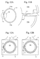
- the slide metal piece 10 shown in Fig. 11 is mounted in the hole 2 of the connecting rod body having the structure described above.
- the slide metal piece 10 comprises two ring halves 10a and 10b obtained by dividing the ring. At one mating portion of the ring halves 10a and 10b, nails 11 which extend from the outer periphery side are formed so as to be opposite to each other.
- the slide metal piece 10 is fit into the hole 2 by the nails 11 being accommodated in the grooves 5 of the connecting rods, and the slide metal piece is mounted into the hole 2 with a fixed tightness by tightening the bolts. Furthermore, relative movement of the slide metal piece 10 is prevented by the end surfaces of the nails 11 which are accommodated in the grooves 5, being caused to abut the end surface of the rod portion 3 or the cap portion 4.
- the rod portion 3 and the cap portion 4 are formed separately by sintering, forging, casting or the like, but they may also be formed integrally.
- the connecting rod may be formed first, and then the hole and the grooves are mechanically machined.
- the rod portion and the cap portion are then divided by being split so as to break, and thus have a similar structure to that described above, and then the slide metal piece is mounted.
- the machining of grooves like those shown in Fig. 10B is difficult.
- the connecting rod is machined to form grooves which straddle the rod portion 3 and the cap portion 4.
- the slide metal piece may be mounted without providing grooves for fixing the slide metal piece.
- Fig. 12A is a cross sectional view showing the breaking-split type connecting rod described above in a state in which the crank pin 15 is mounted. Because the nail 11 of the slide metal piece 10 does not abut the end surface inside the groove 5, as shown in Fig. 12B, the slide metal piece 10 may rotate due to deformation of the large end 1 caused by load being exerted on the connecting rod. In addition, by being deformed from the unloaded state in Fig. 13A, to the state in Fig. 13B in which the large end was deformed in the longitudinal direction thereof, as shown in Fig. 13C, the nail 11 is pressed in the direction of the arrow and there is a danger that the base plate B will eventually breaking due to fatigue. Also, broken pieces from the nail 11 may become caught between the crank pin 15 and the slide metal piece 10, and in the worst case, the slide metal piece 10 and the crank pin 15 may heat up.
- a slide metal piece 10 having no nail may also be used. In this case, it is easier for the large end to deform due to load applied to the connecting rod than in the case described above in which the slide metal piece is provided with nails.
- crush relief portions 20 are formed at both ends of the ring halves 10a and 10b which comprise the slide metal piece 10. The crush relief portion 20 is formed such that its thickness decreases as the end thereof is approached, by causing the diameter of the inner peripheral surface to gradually increase as the end is approached.
- the joint surface may be slid. In this case, the crush relief portions 20 prevent localized contact between the slide metal piece 10 and the crank pin 15.
- the crush height (the height of the slide metal piece which projects from the hole in the large end in an unloaded state) is excessive, due to the elastic deformation of the mating portion of the ring halves 10a and 10b, the crush height portion distends toward the inner side, and the effective inner diameter of the shaft receiving metal piece is decreased. In that case also, the crush relief portion 20 functions to prevent localized contact between the slide metal piece 10 and the crank pin 15.
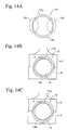
- the crush relief portion 20 is not able to function to prevent the localized contact between the slide metal piece 10 and the crank pin 15. That is to say, the crush relief portion 20 functions to prevent localized contact between the slide metal piece 10 and the crank pin 15 along the direction of the joint surface of the rod portion 3 and the cap portion 4. Accordingly, when as shown in Fig. 14C, the slide metal piece 10 rotates and the phase is slid, the portion which is slid and distends towards the inner side becomes close to the crank pin 15 side, and thus there is localized contact between the sliding portion and the crank pin 15. Furthermore, when the large end 1 in an unloaded state shown in Fig. 13A is deformed in the longitudinal direction so as to be in the state shown in the Fig. 13B, localized contact is more intense, and this may cause great damage to the inner peripheral surface of the slide metal piece 10.
- an object of the present invention is to provide a connecting rod in which rotation and relative slippage of the slide metal piece is restricted, and the problems described above are eliminated.
- the present invention is a connecting rod comprising a hole in the end of the connecting rod main body, the end being divided into a plurality of parts which are in a circumferential direction with respect to the hole and a slide member is disposed on the inner peripheral surface of the hole, wherein the inner peripheral surface of the hole is provided with slits which extend in one direction at an angle of 13 to 90° with respect to the circumferential direction.
- slits are provided at a predetermined angle in a circumferential direction with respect to the inner peripheral surface of an end of the connecting rod main body.
- the slits may be formed by a polishing process such honing, grinding with a grindstone, or by carrying out shaving using a bite, or with a rotating tool such as a drill, a reamer, an end mill or the like.
- the angle of the slits with respect to the circumferential direction of the hole can be set at 13 to 90°. It is to be noted that for making the angle of the slits 90°, broaching, for example, may be carried out. However, in the case of the rotation processing, if consideration is given to processability, it is preferable that the slit angle does not exceed 35°.
- the tool such as the grindstone, the bite and the like, may also be inserted from the direction opposite to the direction referred to above to form slits which cross the slits which were first formed (cross slitting).
- the present invention is a connecting rod comprising a hole in the end of the connecting rod main body, the end being divided into a plurality of parts which are in a circumferential direction with respect to the hole and a slide member is disposed on the inner peripheral surface of the hole, wherein the inner peripheral surface of the hole is provided with slits which extend in one direction at an angle of 17 to 90° with respect to the circumferential direction and also with slits that extend in a direction which crosses the one direction.
- the slits will form a net meshing and thus there is some reduction in frictional resistance. For this reason, it is necessary to set the angle so as to be larger in the case of cross slitting than in the case of linear slitting.
- Fig. 1A is an unfolded plane view of the inner peripheral surface of the hole 2 formed in the large end of the connecting rod.
- the transverse direction in these figures is the circumferential direction.
- slits L are formed by linear slitting, at an angle ⁇ in the circumferential direction.
- the slits L are lines of unevenness caused by using a tool such as a honing grindstone for example, to mechanically process the material surface.
- the angle ⁇ of the slits L in the circumferential direction is set at 13 to 90° by the adjustment of the rotation speed and the conveying speed of the tool.
- Fig. 1B shows the hole 2 having slits L formed, wherein slitting is carried out by a tool being conveyed in the direction opposite to that in which it was conveyed in Fig. 1A, thus forming slits L' which cross the slits L.
- the angle of the slits L and L' is set at 17 to 90°.
- the slide member is preferably mounted in the hole such that the tightness of the slide member which is defined by the difference between the outer peripheral length thereof and the inner peripheral length of the hole, is made to be 0.05 mm or greater.
- the slide metal piece is generally mounted on the large end, but the present invention may be applied by disposing the slide metal piece at only the small end, or at both the large end and the small end. Furthermore, in the present invention, in the case where the nail of the slide metal piece does not abut an end surface of the rod portion or the like, the effect of the nail is fully exhibited. However, the structure in which the nail of the slide metal piece abuts the rod portion and the like (see Fig. 10A) may also be applied. In that case, the relative slippage of the slide metal piece with respect to the hole at the time when the large end is deformed due to the load exerted on the connecting rod decreases, and thus the generation of fretting can be controlled.
- Fig. 2 is a perspective view of the slide metal piece (slide member) 10 of the example, which is formed for measuring slip torque of the slide metal piece with respect to the hole of the large end.
- the ring slide metal piece of the example is formed in the same manner as the actual slide metal piece, except that a notch 10c for engagement with the torque meter jig is formed at the end of the ring halves 10a and 10b.
- As the slide metal piece 10 an SP material whose outer peripheral surface was plated with Ni, whose inner peripheral surface was plated with Pb-Sn-Cu and whose entire surface was subsequently flush plated with Sn was used.
- Fig. 3 shows the steps for mounting the slide metal piece 10 in the large end 1 of the connecting rod.
- the outer diameter of the slide metal piece 10 is set so as to be larger than the inner diameter of the hole 2 of the large end 1.
- the large end 1 protrudes by the amount of the crush height.
- the bolts 18 are tightened in this state, the slide metal piece 10 elastically deforms as shown in Fig. 3B and the large end 1 is in the hole 2 in a state in which it is pressure-inserted.
- the tightness is a value obtained by subtracting the inner peripheral length of the hole 2 from the outer peripheral length of the slide metal piece 10.
- the connecting rod main body portion is one formed by forging an FC-0205 sintered member and dividing the large end 1 so as to be split in the longitudinal direction thereof.
- the tightness of the slide metal piece 10 was set to 0.1 mm and the surface roughness (Ry) of the hole 2 of the large end 1 was set to 2 to 3 ⁇ m.
- the angle of the slits in the circumferential direction was then changed and the slip torque was measured.
- the results are shown in Fig. 4. It is to be noted that in the state of Fig. 3B, the torque meter jig is engaged with the notch 10c of the slide metal piece 10, and torque is applied to the jig.
- the torque when the slide metal piece 10 rotates relative to the hole 2 is referred to as the slip torque.
- the slip torque increases as the slit angle increases.
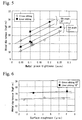
- the surface roughness (Ry) of the hole 2 of the large end 1 was set to 2 to 3 ⁇ m and the slit angle was set to be 15° and 30°.
- the tightness of the slide metal piece 10 was varied and the slip torque was measured.
- the results are shown in Fig. 5.
- the slip torque was changed by the slit angle. That is to say, in the case where the slit angle is 30°, in the case of both linear slitting and cross slitting, as long as the tightness is no less than 0.05 mm, the slip torque will be not be less than 15 kgf ⁇ m. Also, in the case where the slit angle was 15° and the slitting was linear, if the tightness is no less than 0.07 mm, the slip torque will be no be less than 15 kgf ⁇ m.
- the tightness of the slide metal piece 10 was set to be 0.1 mm and also the slit angle was set to 15°.
- the surface roughness (Ry) of the inner peripheral portion of the hole 2 of the large end 1 was changed and the slip torque was measured.
- the results are shown in Fig. 6.
- Fig. 6 As shown in Fig. 6, as the surface roughness increases, there is a tendency for the slip torque to increase, but it can be seen that the effect of surface roughness is limited. Thus, a surface roughness of the inner peripheral portion of the hole 2 of 2 ⁇ m can be considered to be sufficient.
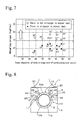
- the tightness of the slide metal piece 10 was set to 0.1 mm, the surface roughness (Ry) of the hole 2 of the large end 1 was set to 2 to 3 ⁇ m, and various slit angles were set and cross slitting was carried out.
- the inner diameter of the hole 2 of the large end 1 was changed and the slit torque was measured.
- the slide metal piece used for measuring was formed in the same manner as that shown in Fig. 11, and the connecting rod was formed with this slide metal piece. The actual testing was then carried out. These results are shown in Fig. 7. As can be seen from Fig. 7, the internal diameter of the hole 2 has no effect on the slip torque. Furthermore, it was confirmed that as long as the slip torque is no less than 15 kgf ⁇ m, the slide metal piece was not slid in the actual test.
- the tightness of the slide metal piece is to be appropriately set in accordance with the slit angle such that the slip torque is greater than or equal to 15 kgf ⁇ m.
- the tightness of the slide metal piece it is sufficient for the tightness of the slide metal piece to be 0.05 mm or more, and in the case where the slit angle is 15° and slitting is linear, the tightness should be 0.07 mm or more.
- the slide metal piece tightness 0.1 mm or more.
- the range for the tightness of the slide metal piece is preferably to 0.05 mm or greater, more preferably 0.07 mm or greater, and even more preferably, 0.1 mm or greater.
- a slide metal piece the same as that of the actual test above, and in which the slit angles are 17° (cross slitting) was used, and as shown in Fig. 8, the relative slippage was measured.
- the slide metal piece 10 was mounted in the large end 1 and a crank pin 15 was fit into the slide metal piece 10.
- the mating surface at the left side of the ring halves 10a and 10b which form the slide metal piece 10 was used as a reference position, and from this reference position, the ring half 10a was moved in a clockwise direction, and a target plate 25 which extends in the radial direction was fixed to the 10°, 50°, 130°, and 170° positions, respectively.
- a distance sensor 30 which causes the detecting portion to approach the target plate 25, was mounted on the rod portion 3 of the large end 1.
- a load of approximately 2000 kgf was applied to the crank pin 15 and the connecting rod, and both were deformed so as to be pulled apart in the vertical direction in the figure.
- the target plate 25 moves away from the distance sensor 30. The amount of movement was then measured as relative slippage.
- the relative slippage was at most, 4 ⁇ m less than that in which the slit angle of the slide metal piece mounted was 0.5°. From this it can be seen that the present invention is effective in preventing rotation of the slide metal piece, and in restricting relative slippage.
Landscapes
- Engineering & Computer Science (AREA)
- General Engineering & Computer Science (AREA)
- Mechanical Engineering (AREA)
- Shafts, Cranks, Connecting Bars, And Related Bearings (AREA)
Abstract
Description
Claims (3)
- An internal combustion engine connecting rod comprising a hole in an end of the connecting rod main body, the end being divided into a plurality of parts which are in a circumferential direction with respect to the hole, and a slide member is disposed on an inner peripheral surface of the hole, wherein the inner peripheral surface of the hole is provided with slits extending in one direction at an angle of 13 to 90° with respect to the circumferential direction.
- An internal combustion engine connecting rod comprising a hole in an end of the connecting rod main body, the end being divided into a plurality of parts which are in a circumferential direction with respect to the hole, and a slide member is disposed on an inner peripheral surface of the hole, wherein the inner peripheral surface of the hole is provided with slits extending in one direction at an angle of 17 to 90° with respect to the circumferential direction, and slits that extend in a direction crossing the one direction.
- The internal combustion engine connecting rod of Claim 1 or 2, wherein when the slide member is mounted in the hole and a force causing relative rotation of the slide member and the hole is applied, the slip torque necessary for causing relative rotation of the slide member and the hole is no less than 15 kgf·m.
Applications Claiming Priority (3)
| Application Number | Priority Date | Filing Date | Title |
|---|---|---|---|
| JP2000235599A JP2002048124A (en) | 2000-08-03 | 2000-08-03 | Connecting rod for internal combustion engine |
| JP2000235599 | 2000-08-03 | ||
| PCT/JP2001/004558 WO2002012739A1 (en) | 2000-08-03 | 2001-05-30 | Internal combustion engine connecting rod |
Publications (3)
| Publication Number | Publication Date |
|---|---|
| EP1223356A1 true EP1223356A1 (en) | 2002-07-17 |
| EP1223356A4 EP1223356A4 (en) | 2007-01-17 |
| EP1223356B1 EP1223356B1 (en) | 2013-03-13 |
Family
ID=18727787
Family Applications (1)
| Application Number | Title | Priority Date | Filing Date |
|---|---|---|---|
| EP01934425A Expired - Lifetime EP1223356B1 (en) | 2000-08-03 | 2001-05-30 | Internal combustion engine connecting rod |
Country Status (5)
| Country | Link |
|---|---|
| US (1) | US6637400B2 (en) |
| EP (1) | EP1223356B1 (en) |
| JP (1) | JP2002048124A (en) |
| BR (1) | BR0107067B1 (en) |
| WO (1) | WO2002012739A1 (en) |
Cited By (4)
| Publication number | Priority date | Publication date | Assignee | Title |
|---|---|---|---|---|
| DE102005032852A1 (en) * | 2005-07-14 | 2007-01-25 | Federal-Mogul Wiesbaden Gmbh & Co. Kg | Bearing shell and method for its production |
| DE10325910B4 (en) * | 2002-08-02 | 2010-03-18 | Mauser-Werke Oberndorf Maschinenbau Gmbh | Method for introducing structures into abutment surfaces, device for introducing such structures and non-positively connected bodies |
| WO2010115518A3 (en) * | 2009-04-08 | 2011-06-16 | Robert Bosch Gmbh | Grooved bearing sleeve for an externally toothed gear machine |
| EP3173638A4 (en) * | 2015-02-27 | 2017-06-21 | Taiho Kogyo Co., Ltd | Bearing and bearing device |
Families Citing this family (5)
| Publication number | Priority date | Publication date | Assignee | Title |
|---|---|---|---|---|
| US7703431B2 (en) * | 2002-07-26 | 2010-04-27 | Cummins, Inc. | Connecting rod apparatus and method |
| ES2241944T3 (en) * | 2002-11-16 | 2005-11-01 | GEHRING GMBH & CO. KG | ROD AND PROCEDURE FOR MANUFACTURING. |
| US7418886B2 (en) * | 2002-12-26 | 2008-09-02 | Yamaha Hatsudoki Kabushiki Kaisha | Split type connecting rod |
| DE112009000365B4 (en) * | 2008-05-19 | 2015-08-06 | Mitsubishi Electric Corporation | Fastening device for a intake exhaust gas recirculation valve |
| DE102010052004B4 (en) * | 2010-11-19 | 2012-06-21 | Audi Ag | Asymmetrically split plain bearing for radial bearing shell mounting |
Family Cites Families (5)
| Publication number | Priority date | Publication date | Assignee | Title |
|---|---|---|---|---|
| US3705753A (en) * | 1970-08-03 | 1972-12-12 | Gen Motors Corp | Method and means for reducing fretting of contacting surfaces |
| DE3328509C1 (en) * | 1983-08-06 | 1985-04-11 | Glyco-Metall-Werke Daelen & Loos Gmbh, 6200 Wiesbaden | Plain bearing arrangement |
| JP3070815B2 (en) * | 1993-09-03 | 2000-07-31 | トヨタ自動車株式会社 | Slide bearing structure |
| JP3416367B2 (en) | 1995-11-22 | 2003-06-16 | 三菱重工業株式会社 | Slide bearing device |
| JPH10131969A (en) | 1996-10-30 | 1998-05-22 | Mitsubishi Heavy Ind Ltd | Sliding bearing |
-
2000
- 2000-08-03 JP JP2000235599A patent/JP2002048124A/en active Pending
-
2001
- 2001-05-30 US US10/088,510 patent/US6637400B2/en not_active Expired - Lifetime
- 2001-05-30 EP EP01934425A patent/EP1223356B1/en not_active Expired - Lifetime
- 2001-05-30 WO PCT/JP2001/004558 patent/WO2002012739A1/en not_active Ceased
- 2001-05-30 BR BRPI0107067-3A patent/BR0107067B1/en not_active IP Right Cessation
Cited By (8)
| Publication number | Priority date | Publication date | Assignee | Title |
|---|---|---|---|---|
| DE10325910B4 (en) * | 2002-08-02 | 2010-03-18 | Mauser-Werke Oberndorf Maschinenbau Gmbh | Method for introducing structures into abutment surfaces, device for introducing such structures and non-positively connected bodies |
| DE10362303B4 (en) * | 2002-08-02 | 2011-01-27 | Mauser-Werke Oberndorf Maschinenbau Gmbh | Device for surface structuring |
| DE10325910C5 (en) * | 2002-08-02 | 2017-01-26 | Mauser-Werke Oberndorf Maschinenbau Gmbh | Method for introducing structures into abutment surfaces, device for introducing such structures and non-positively connected bodies |
| DE102005032852A1 (en) * | 2005-07-14 | 2007-01-25 | Federal-Mogul Wiesbaden Gmbh & Co. Kg | Bearing shell and method for its production |
| DE102005032852B4 (en) * | 2005-07-14 | 2009-08-27 | Federal-Mogul Wiesbaden Gmbh & Co. Kg | Bearing shell and method for its production |
| WO2010115518A3 (en) * | 2009-04-08 | 2011-06-16 | Robert Bosch Gmbh | Grooved bearing sleeve for an externally toothed gear machine |
| EP3173638A4 (en) * | 2015-02-27 | 2017-06-21 | Taiho Kogyo Co., Ltd | Bearing and bearing device |
| US10132348B2 (en) | 2015-02-27 | 2018-11-20 | Taiho Kogyo Co., Ltd. | Bearing and bearing device |
Also Published As
| Publication number | Publication date |
|---|---|
| EP1223356A4 (en) | 2007-01-17 |
| BR0107067B1 (en) | 2009-08-11 |
| WO2002012739A1 (en) | 2002-02-14 |
| US6637400B2 (en) | 2003-10-28 |
| EP1223356B1 (en) | 2013-03-13 |
| JP2002048124A (en) | 2002-02-15 |
| BR0107067A (en) | 2002-06-11 |
| US20020148434A1 (en) | 2002-10-17 |
Similar Documents
| Publication | Publication Date | Title |
|---|---|---|
| US5307708A (en) | Camshaft for controlling valves in internal combustion engines | |
| EP1223356B1 (en) | Internal combustion engine connecting rod | |
| EP3759366B1 (en) | Double row spherical roller bearing | |
| EP1957758B1 (en) | Assembly comprising a turbocharger bearing housing and a semi-floating bearing | |
| EP1761708B1 (en) | Device and method for detachably connecting an impeller to a shaft | |
| EP2932123B1 (en) | Torque limiting tolerance ring | |
| CA2863320C (en) | Inner ring with undercut to improve tang flexibility | |
| EP1479952A2 (en) | Shaft seal mechanism | |
| JP6223562B2 (en) | Tolerance ring, assembly with tolerance ring, and method for splitting torque transmission | |
| US8251590B2 (en) | Anti-rotation bearing assembly and bearing | |
| US6997617B2 (en) | Roller bearing | |
| JPS5926805B2 (en) | Fixing method of fitting member to shaft part | |
| KR940005891A (en) | Shrow member of Shrow compressor and processing method thereof | |
| US20100166350A1 (en) | Split-type sliding bearing for crankshaft in internal combustion engine and split-type sliding bearing device | |
| JP5492811B2 (en) | Scroll compressor | |
| EP2728211B1 (en) | Halved sliding bearing and method for producing same | |
| CN100333854C (en) | Shaft and its forming device | |
| EP4102088A1 (en) | Roller bearing | |
| JP2583628Y2 (en) | Bearing washers for split bearings | |
| KR20080084983A (en) | Precise placement and repositioning of powder metal parts | |
| JPH089479Y2 (en) | Assembly camshaft | |
| JP2004108513A (en) | Roller bearing | |
| WO2019234876A1 (en) | Multi-link piston crank mechanism for internal combustion engine | |
| JPS59169734A (en) | Binding method of shaft and engaging member | |
| JPH06129419A (en) | Ball joint device |
Legal Events
| Date | Code | Title | Description |
|---|---|---|---|
| PUAI | Public reference made under article 153(3) epc to a published international application that has entered the european phase |
Free format text: ORIGINAL CODE: 0009012 |
|
| 17P | Request for examination filed |
Effective date: 20020403 |
|
| AK | Designated contracting states |
Kind code of ref document: A1 Designated state(s): DE GB |
|
| A4 | Supplementary search report drawn up and despatched |
Effective date: 20061215 |
|
| RIC1 | Information provided on ipc code assigned before grant |
Ipc: F16C 33/10 20060101ALI20061211BHEP Ipc: F16C 17/02 20060101ALI20061211BHEP Ipc: F16C 9/04 20060101AFI20020215BHEP |
|
| 17Q | First examination report despatched |
Effective date: 20080415 |
|
| GRAP | Despatch of communication of intention to grant a patent |
Free format text: ORIGINAL CODE: EPIDOSNIGR1 |
|
| GRAS | Grant fee paid |
Free format text: ORIGINAL CODE: EPIDOSNIGR3 |
|
| GRAA | (expected) grant |
Free format text: ORIGINAL CODE: 0009210 |
|
| RIN1 | Information on inventor provided before grant (corrected) |
Inventor name: SATOU, YASUNORI Inventor name: IIDA, ZENJI Inventor name: SUZUKI, SHIGERU Inventor name: MIDORIKAWA, TERUAKI |
|
| AK | Designated contracting states |
Kind code of ref document: B1 Designated state(s): DE GB |
|
| REG | Reference to a national code |
Ref country code: GB Ref legal event code: FG4D |
|
| REG | Reference to a national code |
Ref country code: DE Ref legal event code: R096 Ref document number: 60147766 Country of ref document: DE Effective date: 20130508 |
|
| PGFP | Annual fee paid to national office [announced via postgrant information from national office to epo] |
Ref country code: DE Payment date: 20130328 Year of fee payment: 13 |
|
| PLBE | No opposition filed within time limit |
Free format text: ORIGINAL CODE: 0009261 |
|
| STAA | Information on the status of an ep patent application or granted ep patent |
Free format text: STATUS: NO OPPOSITION FILED WITHIN TIME LIMIT |
|
| 26N | No opposition filed |
Effective date: 20131216 |
|
| GBPC | Gb: european patent ceased through non-payment of renewal fee |
Effective date: 20130613 |
|
| REG | Reference to a national code |
Ref country code: DE Ref legal event code: R097 Ref document number: 60147766 Country of ref document: DE Effective date: 20131216 |
|
| PG25 | Lapsed in a contracting state [announced via postgrant information from national office to epo] |
Ref country code: GB Free format text: LAPSE BECAUSE OF NON-PAYMENT OF DUE FEES Effective date: 20130613 |
|
| REG | Reference to a national code |
Ref country code: DE Ref legal event code: R119 Ref document number: 60147766 Country of ref document: DE |
|
| REG | Reference to a national code |
Ref country code: DE Ref legal event code: R119 Ref document number: 60147766 Country of ref document: DE Effective date: 20141202 |
|
| PG25 | Lapsed in a contracting state [announced via postgrant information from national office to epo] |
Ref country code: DE Free format text: LAPSE BECAUSE OF NON-PAYMENT OF DUE FEES Effective date: 20141202 |