EP1223324A2 - Device and method for suppressing hydrocarbon-discharge for vehicle - Google Patents
Device and method for suppressing hydrocarbon-discharge for vehicle Download PDFInfo
- Publication number
- EP1223324A2 EP1223324A2 EP02000897A EP02000897A EP1223324A2 EP 1223324 A2 EP1223324 A2 EP 1223324A2 EP 02000897 A EP02000897 A EP 02000897A EP 02000897 A EP02000897 A EP 02000897A EP 1223324 A2 EP1223324 A2 EP 1223324A2
- Authority
- EP
- European Patent Office
- Prior art keywords
- temperature
- internal combustion
- combustion engine
- adsorbent
- engine
- Prior art date
- Legal status (The legal status is an assumption and is not a legal conclusion. Google has not performed a legal analysis and makes no representation as to the accuracy of the status listed.)
- Granted
Links
Images



Classifications
-
- B—PERFORMING OPERATIONS; TRANSPORTING
- B60—VEHICLES IN GENERAL
- B60W—CONJOINT CONTROL OF VEHICLE SUB-UNITS OF DIFFERENT TYPE OR DIFFERENT FUNCTION; CONTROL SYSTEMS SPECIALLY ADAPTED FOR HYBRID VEHICLES; ROAD VEHICLE DRIVE CONTROL SYSTEMS FOR PURPOSES NOT RELATED TO THE CONTROL OF A PARTICULAR SUB-UNIT
- B60W10/00—Conjoint control of vehicle sub-units of different type or different function
- B60W10/04—Conjoint control of vehicle sub-units of different type or different function including control of propulsion units
- B60W10/06—Conjoint control of vehicle sub-units of different type or different function including control of propulsion units including control of combustion engines
-
- B—PERFORMING OPERATIONS; TRANSPORTING
- B60—VEHICLES IN GENERAL
- B60K—ARRANGEMENT OR MOUNTING OF PROPULSION UNITS OR OF TRANSMISSIONS IN VEHICLES; ARRANGEMENT OR MOUNTING OF PLURAL DIVERSE PRIME-MOVERS IN VEHICLES; AUXILIARY DRIVES FOR VEHICLES; INSTRUMENTATION OR DASHBOARDS FOR VEHICLES; ARRANGEMENTS IN CONNECTION WITH COOLING, AIR INTAKE, GAS EXHAUST OR FUEL SUPPLY OF PROPULSION UNITS IN VEHICLES
- B60K6/00—Arrangement or mounting of plural diverse prime-movers for mutual or common propulsion, e.g. hybrid propulsion systems comprising electric motors and internal combustion engines
- B60K6/20—Arrangement or mounting of plural diverse prime-movers for mutual or common propulsion, e.g. hybrid propulsion systems comprising electric motors and internal combustion engines the prime-movers consisting of electric motors and internal combustion engines, e.g. HEVs
- B60K6/42—Arrangement or mounting of plural diverse prime-movers for mutual or common propulsion, e.g. hybrid propulsion systems comprising electric motors and internal combustion engines the prime-movers consisting of electric motors and internal combustion engines, e.g. HEVs characterised by the architecture of the hybrid electric vehicle
- B60K6/44—Series-parallel type
- B60K6/445—Differential gearing distribution type
-
- F—MECHANICAL ENGINEERING; LIGHTING; HEATING; WEAPONS; BLASTING
- F01—MACHINES OR ENGINES IN GENERAL; ENGINE PLANTS IN GENERAL; STEAM ENGINES
- F01N—GAS-FLOW SILENCERS OR EXHAUST APPARATUS FOR MACHINES OR ENGINES IN GENERAL; GAS-FLOW SILENCERS OR EXHAUST APPARATUS FOR INTERNAL-COMBUSTION ENGINES
- F01N13/00—Exhaust or silencing apparatus characterised by constructional features
- F01N13/009—Exhaust or silencing apparatus characterised by constructional features having two or more separate purifying devices arranged in series
-
- F—MECHANICAL ENGINEERING; LIGHTING; HEATING; WEAPONS; BLASTING
- F01—MACHINES OR ENGINES IN GENERAL; ENGINE PLANTS IN GENERAL; STEAM ENGINES
- F01N—GAS-FLOW SILENCERS OR EXHAUST APPARATUS FOR MACHINES OR ENGINES IN GENERAL; GAS-FLOW SILENCERS OR EXHAUST APPARATUS FOR INTERNAL-COMBUSTION ENGINES
- F01N3/00—Exhaust or silencing apparatus having means for purifying, rendering innocuous, or otherwise treating exhaust
- F01N3/08—Exhaust or silencing apparatus having means for purifying, rendering innocuous, or otherwise treating exhaust for rendering innocuous
- F01N3/0807—Exhaust or silencing apparatus having means for purifying, rendering innocuous, or otherwise treating exhaust for rendering innocuous by using absorbents or adsorbents
- F01N3/0814—Exhaust or silencing apparatus having means for purifying, rendering innocuous, or otherwise treating exhaust for rendering innocuous by using absorbents or adsorbents combined with catalytic converters, e.g. NOx absorption/storage reduction catalysts
-
- F—MECHANICAL ENGINEERING; LIGHTING; HEATING; WEAPONS; BLASTING
- F01—MACHINES OR ENGINES IN GENERAL; ENGINE PLANTS IN GENERAL; STEAM ENGINES
- F01N—GAS-FLOW SILENCERS OR EXHAUST APPARATUS FOR MACHINES OR ENGINES IN GENERAL; GAS-FLOW SILENCERS OR EXHAUST APPARATUS FOR INTERNAL-COMBUSTION ENGINES
- F01N3/00—Exhaust or silencing apparatus having means for purifying, rendering innocuous, or otherwise treating exhaust
- F01N3/08—Exhaust or silencing apparatus having means for purifying, rendering innocuous, or otherwise treating exhaust for rendering innocuous
- F01N3/0807—Exhaust or silencing apparatus having means for purifying, rendering innocuous, or otherwise treating exhaust for rendering innocuous by using absorbents or adsorbents
- F01N3/0828—Exhaust or silencing apparatus having means for purifying, rendering innocuous, or otherwise treating exhaust for rendering innocuous by using absorbents or adsorbents characterised by the absorbed or adsorbed substances
- F01N3/0835—Hydrocarbons
-
- F—MECHANICAL ENGINEERING; LIGHTING; HEATING; WEAPONS; BLASTING
- F01—MACHINES OR ENGINES IN GENERAL; ENGINE PLANTS IN GENERAL; STEAM ENGINES
- F01N—GAS-FLOW SILENCERS OR EXHAUST APPARATUS FOR MACHINES OR ENGINES IN GENERAL; GAS-FLOW SILENCERS OR EXHAUST APPARATUS FOR INTERNAL-COMBUSTION ENGINES
- F01N3/00—Exhaust or silencing apparatus having means for purifying, rendering innocuous, or otherwise treating exhaust
- F01N3/08—Exhaust or silencing apparatus having means for purifying, rendering innocuous, or otherwise treating exhaust for rendering innocuous
- F01N3/10—Exhaust or silencing apparatus having means for purifying, rendering innocuous, or otherwise treating exhaust for rendering innocuous by thermal or catalytic conversion of noxious components of exhaust
- F01N3/18—Exhaust or silencing apparatus having means for purifying, rendering innocuous, or otherwise treating exhaust for rendering innocuous by thermal or catalytic conversion of noxious components of exhaust characterised by methods of operation; Control
- F01N3/20—Exhaust or silencing apparatus having means for purifying, rendering innocuous, or otherwise treating exhaust for rendering innocuous by thermal or catalytic conversion of noxious components of exhaust characterised by methods of operation; Control specially adapted for catalytic conversion
- F01N3/2006—Periodically heating or cooling catalytic reactors, e.g. at cold starting or overheating
-
- F—MECHANICAL ENGINEERING; LIGHTING; HEATING; WEAPONS; BLASTING
- F02—COMBUSTION ENGINES; HOT-GAS OR COMBUSTION-PRODUCT ENGINE PLANTS
- F02D—CONTROLLING COMBUSTION ENGINES
- F02D41/00—Electrical control of supply of combustible mixture or its constituents
- F02D41/02—Circuit arrangements for generating control signals
- F02D41/021—Introducing corrections for particular conditions exterior to the engine
- F02D41/0235—Introducing corrections for particular conditions exterior to the engine in relation with the state of the exhaust gas treating apparatus
-
- F—MECHANICAL ENGINEERING; LIGHTING; HEATING; WEAPONS; BLASTING
- F02—COMBUSTION ENGINES; HOT-GAS OR COMBUSTION-PRODUCT ENGINE PLANTS
- F02D—CONTROLLING COMBUSTION ENGINES
- F02D41/00—Electrical control of supply of combustible mixture or its constituents
- F02D41/02—Circuit arrangements for generating control signals
- F02D41/04—Introducing corrections for particular operating conditions
- F02D41/06—Introducing corrections for particular operating conditions for engine starting or warming up
- F02D41/062—Introducing corrections for particular operating conditions for engine starting or warming up for starting
-
- F—MECHANICAL ENGINEERING; LIGHTING; HEATING; WEAPONS; BLASTING
- F02—COMBUSTION ENGINES; HOT-GAS OR COMBUSTION-PRODUCT ENGINE PLANTS
- F02N—STARTING OF COMBUSTION ENGINES; STARTING AIDS FOR SUCH ENGINES, NOT OTHERWISE PROVIDED FOR
- F02N11/00—Starting of engines by means of electric motors
- F02N11/08—Circuits specially adapted for starting of engines
- F02N11/0814—Circuits specially adapted for starting of engines comprising means for controlling automatic idle-start-stop
- F02N11/0818—Conditions for starting or stopping the engine or for deactivating the idle-start-stop mode
-
- F—MECHANICAL ENGINEERING; LIGHTING; HEATING; WEAPONS; BLASTING
- F02—COMBUSTION ENGINES; HOT-GAS OR COMBUSTION-PRODUCT ENGINE PLANTS
- F02N—STARTING OF COMBUSTION ENGINES; STARTING AIDS FOR SUCH ENGINES, NOT OTHERWISE PROVIDED FOR
- F02N2200/00—Parameters used for control of starting apparatus
- F02N2200/02—Parameters used for control of starting apparatus said parameters being related to the engine
- F02N2200/026—Catalyst temperature
-
- Y—GENERAL TAGGING OF NEW TECHNOLOGICAL DEVELOPMENTS; GENERAL TAGGING OF CROSS-SECTIONAL TECHNOLOGIES SPANNING OVER SEVERAL SECTIONS OF THE IPC; TECHNICAL SUBJECTS COVERED BY FORMER USPC CROSS-REFERENCE ART COLLECTIONS [XRACs] AND DIGESTS
- Y02—TECHNOLOGIES OR APPLICATIONS FOR MITIGATION OR ADAPTATION AGAINST CLIMATE CHANGE
- Y02A—TECHNOLOGIES FOR ADAPTATION TO CLIMATE CHANGE
- Y02A50/00—TECHNOLOGIES FOR ADAPTATION TO CLIMATE CHANGE in human health protection, e.g. against extreme weather
- Y02A50/20—Air quality improvement or preservation, e.g. vehicle emission control or emission reduction by using catalytic converters
-
- Y—GENERAL TAGGING OF NEW TECHNOLOGICAL DEVELOPMENTS; GENERAL TAGGING OF CROSS-SECTIONAL TECHNOLOGIES SPANNING OVER SEVERAL SECTIONS OF THE IPC; TECHNICAL SUBJECTS COVERED BY FORMER USPC CROSS-REFERENCE ART COLLECTIONS [XRACs] AND DIGESTS
- Y02—TECHNOLOGIES OR APPLICATIONS FOR MITIGATION OR ADAPTATION AGAINST CLIMATE CHANGE
- Y02T—CLIMATE CHANGE MITIGATION TECHNOLOGIES RELATED TO TRANSPORTATION
- Y02T10/00—Road transport of goods or passengers
- Y02T10/10—Internal combustion engine [ICE] based vehicles
- Y02T10/12—Improving ICE efficiencies
-
- Y—GENERAL TAGGING OF NEW TECHNOLOGICAL DEVELOPMENTS; GENERAL TAGGING OF CROSS-SECTIONAL TECHNOLOGIES SPANNING OVER SEVERAL SECTIONS OF THE IPC; TECHNICAL SUBJECTS COVERED BY FORMER USPC CROSS-REFERENCE ART COLLECTIONS [XRACs] AND DIGESTS
- Y02—TECHNOLOGIES OR APPLICATIONS FOR MITIGATION OR ADAPTATION AGAINST CLIMATE CHANGE
- Y02T—CLIMATE CHANGE MITIGATION TECHNOLOGIES RELATED TO TRANSPORTATION
- Y02T10/00—Road transport of goods or passengers
- Y02T10/10—Internal combustion engine [ICE] based vehicles
- Y02T10/40—Engine management systems
-
- Y—GENERAL TAGGING OF NEW TECHNOLOGICAL DEVELOPMENTS; GENERAL TAGGING OF CROSS-SECTIONAL TECHNOLOGIES SPANNING OVER SEVERAL SECTIONS OF THE IPC; TECHNICAL SUBJECTS COVERED BY FORMER USPC CROSS-REFERENCE ART COLLECTIONS [XRACs] AND DIGESTS
- Y02—TECHNOLOGIES OR APPLICATIONS FOR MITIGATION OR ADAPTATION AGAINST CLIMATE CHANGE
- Y02T—CLIMATE CHANGE MITIGATION TECHNOLOGIES RELATED TO TRANSPORTATION
- Y02T10/00—Road transport of goods or passengers
- Y02T10/60—Other road transportation technologies with climate change mitigation effect
- Y02T10/62—Hybrid vehicles
Definitions
- the invention relates to suppression of the discharge of HC from an internal combustion engine of a vehicle to the atmosphere.
- present-day vehicles are normally provided with a catalytic converter including a catalyst such as a three-way catalyst having the functions of causing noxious components such as NOx, HC, and CO to react with one another and converting them into harmless components such as N 2 , CO 2 , and H 2 O.
- a catalyst such as a three-way catalyst having the functions of causing noxious components such as NOx, HC, and CO to react with one another and converting them into harmless components such as N 2 , CO 2 , and H 2 O.
- an HC adsorbent for temporarily adsorbing and holding a great amount of HC, which is generated especially during cold start of the engine, until the catalyst is warmed up and activated is disposed in an exhaust system upstream of the catalytic converter.
- the HC adsorbent which is disposed upstream of the catalytic converter including the three-way catalyst, is either accommodated in a container different from a container for the catalytic converter or accommodated in the container for the catalytic converter while constituting a stratified structure together with the three-way catalyst.
- the exhaust system of the engine is provided with the HC adsorbent and the catalytic converter that causes HC, CO, and NOx to react with one another and that converts them into harmless components such as N 2 , CO 2 , and H 2 O.
- the HC adsorbent temporarily adsorbs and captures a great amount of HC that is generated during cold start of the engine until the catalytic converter is warmed up and activated by exhaust gas in the engine. As soon as the catalytic converter is warmed up and activated, the catalyst thus activated becomes capable of purifying the HC discharged from the HC adsorbent, which is also warmed up by exhaust gas in the engine in the meantime while losing its HC-adsorbing ability.
- Such a convenient HC-discharge preventing mechanism is obtained in this manner.
- a combination of the HC adsorbent and the HC oxidation catalyst occasionally leads to the possibility that the HC adsorbent might reach a temperature at which HC is discharged before the HC oxidation catalyst reaches its activation temperature and that HC might be discharged to the atmosphere in between times.
- Such a problem constitutes a serious threat especially to an economy-running vehicle equipped with an engine that is stopped temporarily if the vehicle is stopped temporarily because of a red light or traffic jam or to a hybrid vehicle that is suitably driven by either an engine or an electric motor depending on the operational state of the vehicle.
- This is because of the fact that the engine is often stopped temporarily, that the HC adsorbent and the catalytic converter cool off in the meantime, and that cold start of the engine may be repeated many times.
- the invention has been made as a solution to such a problem. It is an object of the invention to reliably suppress the discharge of HC to the atmosphere during cold start of an engine and to thereby improve the properties of exhaust gas in a vehicle whose engine is repeatedly started with great frequency, such as an eco-run vehicle or a hybrid vehicle.
- One aspect of the invention provides an HC-discharge suppressing device and an operational method of suppressing the discharge of HC in a vehicle equipped with an engine that has an exhaust system including an HC adsorbent and an HC oxidation catalyst and that is stopped temporarily upon fulfillment of a predetermined condition for operating the vehicle.
- the operation of the engine is controlled after cold start thereof in accordance with a temperature of the HC adsorbent and the HC oxidation catalyst, in such a manner as to minimize the amount of HC discharged from the exhaust system to the atmosphere.
- the HC-holding performance of the former and the HC-purifying performance of the latter change as shown in Fig. 1.
- the axis of ordinate represents the HC-holding performance and the HC-purifying performance.
- the axis of abscissa intrinsically represents temperatures of the HC adsorbent and the HC oxidation catalyst.
- the temperatures of the HC adsorbent and the HC oxidation catalyst correspond to the elapsed time after cold start of the engine.
- the operation of the engine after cold start thereof is controlled such that the rise of temperatures of the HC adsorbent and the HC oxidation catalyst, which are heated up by exhaust gas in the engine, minimizes the amount of HC discharged to the atmosphere during a period in which exhaust gas in the engine has heated up the HC adsorbent sufficiently but not the HC oxidation catalyst, the area in which a curve indicating the HC-holding performance of the HC adsorbent and a curve indicating the HC-purifying performance of the HC oxidation catalyst overlap with each other is basically increased to a maximum possible extent.
- the device and method as described above may be designed such that if, after cold start of the engine, the temperature of the HC adsorbent has become equal to or higher than a predetermined temperature at which adsorbed HC is discharged but the temperature of the HC oxidation catalyst has not reached a predetermined temperature at which HC is oxidized sufficiently, the engine is not stopped.
- the device and method as described above may be designed such that if, after cold start of the engine, the temperature of the HC adsorbent has temporarily risen to become equal to or higher than the predetermined temperature at which adsorbed HC is discharged, the engine is not stopped until the temperature of the HC adsorbent reaches a predetermined temperature at which the adsorbed HC is estimated to have been discharged sufficiently.
- the device and method as described above may be designed such that if, after cold start of the engine, the temperature of the HC oxidation catalyst has reached a first predetermined temperature at which HC is oxidized sufficiently, and if, after stoppage of the engine, the temperature of the HC oxidation catalyst has fallen to become equal to or lower than a second predetermined temperature at which HC is oxidized sufficiently, the engine is started. It is appropriate herein that the second predetermined temperature be lower than the first predetermined temperature.
- the device and method as described above may be designed such that even if, after cold start of the engine, the temperature of the HC oxidation catalyst has reached a first predetermined temperature at which HC is oxidized sufficiently, and even if, after stoppage of the engine, the temperature of the HC oxidation catalyst has fallen to become equal to or lower than a second predetermined temperature at which HC is oxidized sufficiently, the engine is not started as long as the HC adsorbent is estimated to have sufficiently discharged the HC that was adsorbed at the outset. It is appropriate herein that the second predetermined temperature be lower than the first predetermined temperature.
- the area of intersection of both the curves be passed as quickly as possible and that the area not be passed again.
- the engine is not stopped until the temperature of the HC adsorbent reaches a predetermined temperature at which the adsorbed HC is estimated to have been discharged sufficiently.
- the engine is started unless the HC adsorbent is estimated to have sufficiently discharged the HC that was adsorbed at the outset.
- the operation of the engine may be controlled such that the flow rate of exhaust gas flowing therethrough comes into a range corresponding to an HC-adsorbing capacity of the HC adsorbent.
- the operation of the engine may be performed in a low-load steady state in which the amount of discharged HC is small.
- control of the engine can be performed in much more varieties.
- the vehicle is a hybrid vehicle that can be controlled such that a driving force required of the vehicle is distributed to an engine and a motor after cold start of the engine
- the following measures are advantageous.
- the operation of the engine is controlled such that the flow rate of exhaust gas flowing therethrough comes into a range corresponding to an HC-adsorbing capacity of the HC adsorbent.
- the temperature of the HC oxidation catalyst has not reached the predetermined temperature at which HC is oxidized sufficiently, the operation of the engine is performed in a low-load steady state in which the amount of discharged HC is small.”
- Fig. 2 is an illustrative view of an example of the structure of a power source especially in the case where the HC-discharge suppressing device according to the invention is applied to a hybrid vehicle.
- Fig. 2 shows an internal combustion engine 1 (hereinafter referred to as engine, E).
- a generator (electric power generator, G) 3 and a motor (electric motor, M) 4 are connected to the engine 1 via a drivingly connecting device 2 equipped with a planetary gear mechanism in such a manner that a power is transmitted between the generator 3 and the motor 4.
- the generator 3, the motor 4, and the drivingly connecting device 2 constitute a drivingly connected unit.
- a transmission 5 is also connected to the drivingly connected unit via a shaft portion of the motor 4.
- the engine 1, the generator 3, and the motor 4 are connected to driving wheels 7a, 7b via the transmission 5 and a pair of axles 6a, 6b, respectively, in such a manner as to allow power transmission.
- a differential gear 8 is installed in part of the transmission 5, so that a rotational power transmitted to the axles 6a, 6b via the transmission 5 is differentially transmitted to the driving wheels 7a, 7b respectively.
- Fig. 2 also shows an accumulator (A) 9 performing the function of accumulating electric power like a battery or a capacitor.
- the accumulator 9 is electrically connected to the generator 3 and the motor 4 via an inverter (I) 10.
- the generator 3 By being driven by at least one of the engine 1 and the inertia of the vehicle during deceleration thereof, the generator 3 generates electric power and charges the accumulator 9.
- the motor 4 suitably drives the vehicle using the accumulator 9 as a power source.
- the generator 3 and the motor 4 are provided as separate units according to the structure shown in Fig. 2, they may be replaced by an integral-type unit called a motor-generator, which operates either as a motor or as a generator on the basis of the switching operation of an electric circuit.
- the means referred to as the motor in the present specification in a broader sense than the motor 4 in the embodiment shown in Fig. 2 covers both a means for performing only the function of transmitting electric power like the motor 4 and a means for performing both the functions of transmitting and generating electric power like the motor-generator.
- the means referred to as the generator in the present specification in a broader sense than the generator 3 in the embodiment shown in Fig. 2 covers both a means for performing only the function of generating electric power like the generator 3 and a means for performing both the functions of transmitting and generating electric power like the motor-generator.
- An HC adsorbing device (AB) 11 and a catalytic converter (CC) 12 are disposed in an exhaust system of the engine 1 in this order along the direction in which exhaust gas flows.
- the HC adsorbing device 11 includes an HC adsorbent that adsorbs and captures HC contained in exhaust gas.
- the catalytic converter 12 includes a three-way catalyst. As far as the invention is concerned, the catalytic converter 12 ought to function as an HC oxidation catalyst that oxidizes at least HC. Zeolite and the like are known as an HC adsorbent.
- Such an HC adsorbent performs the function of adsorbing and holding HC at a room temperature (atmospheric temperature), but loses the performance of adsorbing HC if heated up by engine exhaust gas as shown in Fig. 1. If the HC adsorbent adsorbs HC at a low temperature, it discharges the HC when heated up.
- the three-way catalyst contains noble metal components and performs the function of causing HC, CO, and NOx in engine exhaust gas to react with one another and converting them into N 2 , CO 2 , and H 2 O. However, as shown in Fig. 1, the three-way catalyst performs that function only after it has been heated up by engine exhaust gas.
- An electronic control unit (ECU) 13 in which a computer is installed controls the operations of the engine 1, the generator 3, the motor 4, and the transmission 5 as will be described below, and thus performs the operational control of the hybrid vehicle shown in Fig. 2 according to the invention.
- a signal indicating a depression amount Dp of an accelerator pedal and a signal indicating a vehicle speed Sv are input to the electronic control unit 13 as information for controlling the operation of the vehicle on the basis of the intention of a driver and the state of traveling.
- signals indicating an engine temperature Te, a rotational angle ⁇ e of an engine crank shaft, a temperature Tab of the HC adsorbing device 11, a temperature Tcc of the catalytic converter 12 are inputted to the electronic control unit 13 so as to suitably perform the operation control of the vehicle according to the invention.
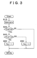
- Fig. 3 is a flowchart showing the HC-discharge suppressing device and the method of operating the device according to the first embodiment of the invention. If it is assumed herein that the engine 1 is at a low temperature and that the operation of the vehicle is started by turning a key switch (not shown) on, the required data as shown in Fig. 2 are read in step 10. Then in step 20, it is determined on the basis of the read data whether or not the temperature Tab of the HC adsorbent in the HC adsorbing device 11 has reached a predetermined temperature Tab0 at which the HC adsorbing device 11 starts discharging the adsorbed HC. If the HC adsorbing device 11 has not been heated up to such a temperature by engine exhaust gas, the control returns to step 10 immediately. Then, the processings in step 10 and step 20 are repeated.
- step 20 If the HC adsorbing device 11 is further heated up to such an extent that the HC adsorbent reaches the predetermined temperature Tab, the result in step 20 becomes positive.
- the control proceeds to step 30 where it is determined whether or not the temperature Tcc of the catalyst in the catalytic converter 12 has reached a predetermined temperature Tcc0 at which HC is oxidized sufficiently. If the catalytic converter 12 has not been heated up sufficiently so that the result in step 30 is negative, the control proceeds to step 80 where a flag Fens for prohibiting the engine 1 from being stopped (stopped temporarily) on the basis of a determination made by the electronic control unit 13 is set as 1.
- the operational control as described above makes an attempt to ensure that the warm-up state of the exhaust system will pass through a region in the neighborhood of the intersection point of the curves as quickly as possible without loitering thereabout. This attempt suppresses the discharge of HC to the atmosphere, which is likely when the engine is started at a low temperature. It is appropriate that the flag Fens that has been set as 1 in step 80 be reset as 0 in step 90 as soon as the temperature Tcc of the catalyst reaches the temperature Tcc0.
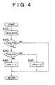
- Fig. 4 is a flowchart similar to the one shown in Fig. 3 and shows the method of operating the HC-discharge suppressing device according to the second embodiment of the invention. It is assumed also herein that the engine 1 is at a low temperature and that the operation of the vehicle is started by turning the key switch (not shown) on.
- the control processings performed in step 10 and step 20 are identical with those shown in Fig. 3.
- the control proceeds to step 40 where it is determined whether or not the temperature Tab of the HC adsorbent has reached a predetermined temperature Tab1, which is higher than Tab0 and at which the adsorbed HC is estimated to have been discharged sufficiently. As long as the result in step 40 is negative, the control proceeds to step 80 where the flag Fens for prohibiting the engine 1 from being stopped (stopped temporarily) is set as 1.
- This embodiment is also designed such that, if the warm-up state of the exhaust system after the cold start of the engine 1 has proceeded more or less toward the intersection point of the curves indicating the HC-adsorbing performance and the HC-purifying performance shown in Fig. 1, the control as described above makes an attempt to ensure that the warm-up state of the exhaust system will pass through the region in the neighborhood of the intersection point of the curves as quickly as possible without loitering thereabout. This attempt suppresses the discharge of HC to the atmosphere, which is likely when the engine is started at a low temperature.
- the flag Fens that has been set as 1 in step 80 be reset as 0 in step 90 if it is determined that the temperature Tab of the HC adsorbent has reached the predetermined temperature Tab1 at which the adsorbed HC is estimated to have been discharged sufficiently.
- Fig. 5 is a flowchart similar to those shown in Figs. 3 and 4 and shows the method of operating the HC-discharge suppressing device according to the third embodiment of the invention. It is assumed also herein that the engine 1 is at a low temperature and that the operation of the vehicle is started by turning the key switch (not shown) on.
- the control processing performed in step 10 is identical with that shown in Figs. 3 and 4.
- the flag F2 is set as 1 when the control reaches later-described step 170.
- the flag F2 is reset as 0 every time the control is started, and remains unchanged until the control proceeds to step 170. Accordingly, the result in step 100 is negative unless the control has reached this step through step 170.
- the control proceeds to step 110.
- step 110 It is determined in step 110 whether or not a flag F1 has been set as 1.
- the flag F1 is set as 1 when the control reaches later-described step 140. For the same reason as described above in regard to the flag F2, the flag F1 is maintained at 0 until the control reaches step 140. Thus, if the control reaches step 110 for the first time, the result is negative. Thus, the control proceeds to step 120 where it is determined whether or not the temperature Tcc of the catalyst of the catalytic converter 12 has reached a predetermined temperature Tcc1 at which HC is oxidized sufficiently. If the result in step 120 is negative, the control returns to step 10 immediately.
- step 120 If the result in step 120 is positive, the control proceeds to step 130 where it is determined whether or not the engine 1 has been stopped temporarily on the basis of a determination made by the electronic control unit 13 during the operational control of the vehicle. The control returns to step 10 immediately unless the engine 1 is stopped temporarily. If the engine 1 is stopped temporarily, the control proceeds to step 140 where the flag F1 is set as 1.
- step 150 it is determined in step 150 whether or not the temperature Tcc of the catalyst in the catalytic converter 12 is maintained equal to or higher than a critical temperature Tcc1- ⁇ T, which is lower than the predetermined temperature Tcc1 by a predetermined temperature difference ⁇ T and above which it is inappropriate for the catalytic converter 12 to accomplish sufficient purification of HC. As long as the result in step 150 is positive, the control returns to step 10 immediately. If the result in step 150 is negative, the control proceeds to step 160 where the engine 1 that has been decoupled from the drive train of the vehicle and that has been stopped temporarily is started.
- the operation of the engine 1 started herein is preferably designed to suit the purpose of suppressing a further drop in temperature of the catalytic converter 12 while minimizing the amount of fuel consumption.
- the control reaches step 160, the engine 1 is started.
- the flag F1 is reset as 0 and the flag F2 is set as 1.
- the same flag as in the embodiment shown in Figs. 3 and 4, that is, the flag Fens for prohibiting the engine 1 from being stopped is set as 1.
- step 100 After the control has passed through step 160 and step 170, the result in step 100 is positive. Therefore, the control then proceeds from step 100 to step 180 where it is determined whether or not the temperature Tcc of the catalyst has again become equal to or higher than the predetermined temperature Tcc1. If the result in step 180 is negative, the control remains unchanged. In other words, at least the operation of the engine 1 is performed without interruption. If it is confirmed in step 180 that the catalytic converter 12 has been warmed up by exhaust gas flowing from the engine 1 that is in operation and that the temperature Tcc has again become equal to or higher than the predetermined temperature Tcc1, the control proceeds to step 190 where the flag Fens for prohibiting the engine 1 from being stopped is reset as 0 and where the flag F2 is also reset as 0. Then, the control returns to its initial state.
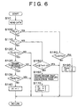
- Fig. 6 is a flowchart similar to that shown in Fig. 5 and shows the method of operating the HC-discharge suppressing device according to the fourth embodiment of the invention.
- This embodiment further includes step 135, which is interposed between step 130 and step 140 in the flowchart of the third embodiment shown in Fig. 5.
- the fourth embodiment is designed as follows. If the results in step 120 and step 130 are positive, it is determined in step 135 whether or not the temperature Tab of the HC adsorbent has reached the predetermined temperature Tab1, which plays the same role as the temperature Tab1 in step 40 of Fig. 4 and at which the adsorbed HC is estimated to have been discharged sufficiently. If the result in step 135 is negative, the control proceeds to step 140.
- step 135 If the result in step 135 is positive, the control immediately returns to the initial state prior to the passage through step 10. This takes into account the fact that it is unclear whether or not the HC adsorbent is estimated to have discharged HC sufficiently even if it is determined in step 120 that the temperature Tcc of the catalytic converter 12 has reached the predetermined temperature Tcc1 that is sufficient to oxidize HC. It is determined in step 135 whether or not the temperature Tab of the HC adsorbent has reached the temperature Tab1, whereby it is determined whether or not the HC adsorbent has discharged HC sufficiently.
- the temperature of the HC oxidation catalyst becomes equal to or lower than a predetermined temperature that is sufficient to oxidize HC after temporary stoppage of the engine 1, it is determined whether to start the engine 1 by determining whether or not the HC adsorbent has sufficiently discharged the HC that was adsorbed at the outset. If the HC adsorbent is estimated to have sufficiently discharged the HC that was adsorbed thereby at the outset, the engine 1 is not restarted after temporary stoppage thereof merely on the basis of a fall in temperature of the HC oxidation catalyst.
- the operation of the fourth embodiment shown in Fig. 6 is identical with the operation of the third embodiment shown in Fig. 5.
- Fig. 7 is a graph showing the method of operating the HC-discharge suppressing device according to the invention from a different angle.
- the HC adsorbent is heated by engine exhaust gas after cold start of the engine 1 and thus gradually loses its HC-adsorbing performance with the lapse of time.
- the HC oxidation catalyst gradually gains its HC-purifying performance with the lapse of time.
- the gain in the HC-purifying performance is temporally retarded with respect to the loss in the HC-adsorbing performance.
- the phenomenon of blow-up occurring immediately after the start of the engine as described above is desirable for the purpose of ensuring startability of the engine.
- the phenomenon of blow-up causes a large amount of HC to be discharged from cylinders of the engine while suppression of the discharge of HC to the atmosphere depends only on the absorption of HC by the HC adsorbent, and creates a possibility that the amount of HC captured by the HC adsorbent might be insufficient.
- this is exactly when the HC-adsorbing performance of the HC adsorbent is about to deteriorate. If the phenomenon of blow-up during the start of the engine 1 is suppressed as indicated by solid lines in the second, third, and fourth stages of Fig.
- the discharge of HC to the atmosphere is suppressed correspondingly.
- This is achieved by controlling the operation of the engine 1 such that the flow rate of exhaust gas comes into a range corresponding to an HC-adsorbing capacity of the HC adsorbent while the temperature of the HC adsorbent is in a temperature range allowing the absorption of HC while performing the operation of the engine 1 in a low-load steady state in which the amount of discharged HC is small.
- the invention provides an HC-discharge suppressing device and an operational method of suppressing the discharge of HC for a vehicle equipped with an engine 1 that has an exhaust system including an HC adsorbent 11 and an HC oxidation catalyst 12 and that is stopped temporarily upon fulfillment of a predetermined condition for operating the vehicle.
- the engine 1 is controlled after cold start thereof in accordance with a temperature of the HC adsorbent 11 and a temperature of the HC oxidation catalyst 12, in such a manner as to minimize the amount of HC discharged from the exhaust system to the atmosphere.
- the invention provides an HC-discharge suppressing device and an operational method of suppressing the discharge of HC for a vehicle equipped with an engine (1) that has an exhaust system including an HC adsorbent (11) and an HC oxidation catalyst (12) and that is stopped temporarily upon fulfillment of a predetermined condition for operating the vehicle.
- the engine (1) is controlled after cold start thereof in accordance with a temperature of the HC adsorbent (11) and a temperature of the HC oxidation catalyst (12), in such a manner as to minimize the amount of HC discharged from the exhaust system to the atmosphere.
Landscapes
- Engineering & Computer Science (AREA)
- Chemical & Material Sciences (AREA)
- Combustion & Propulsion (AREA)
- Mechanical Engineering (AREA)
- General Engineering & Computer Science (AREA)
- Chemical Kinetics & Catalysis (AREA)
- Transportation (AREA)
- Health & Medical Sciences (AREA)
- Toxicology (AREA)
- Exhaust Gas After Treatment (AREA)
- Control Of Vehicle Engines Or Engines For Specific Uses (AREA)
- Combined Controls Of Internal Combustion Engines (AREA)
Abstract
Description
This is because of the fact that the engine is often stopped temporarily, that the HC adsorbent and the catalytic converter cool off in the meantime, and that cold start of the engine may be repeated many times.
Claims (15)
- An operational method of suppressing the discharge of HC in a vehicle equipped with an internal combustion engine (1) that has an exhaust system including an HC adsorbent (11) and an HC oxidation catalyst (12) and that is stopped temporarily upon fulfillment of a predetermined condition for operating of the vehicle, the operational method characterized in that the internal combustion engine (1) is operated after cold start thereof in accordance with a temperature (Tab) of the HC adsorbent (11) and a temperature (Tcc) of the HC oxidation catalyst (12), in such a manner as to minimize the amount of HC discharged from the exhaust system to the atmosphere.
- The operational method according to claim 1,
characterized in that if, after cold start of the internal combustion engine (1), the temperature (Tab) of the HC adsorbent (11) has become equal to or higher than a predetermined temperature (Tab0) at which adsorbed HC is discharged but the temperature (Tcc) of the HC oxidation catalyst (12) has not reached a predetermined temperature (Tcc0) at which HC is oxidized sufficiently, the internal combustion engine (1) is not stopped. - The operational method according to claim 1,
characterized in that if, after cold start of the internal combustion engine (1), the temperature (Tab) of the HC adsorbent (11) has temporarily risen to become equal to or higher than the predetermined temperature (Tab0) at which adsorbed HC is discharged, the internal combustion engine (1) is not stopped until the temperature (Tab) of the HC adsorbent (11) reaches a predetermined temperature (Tab1) at which the adsorbed HC is estimated to have been discharged sufficiently. - The operational method according to claim 1,
characterized in that if, after cold start of the internal combustion engine (1), the temperature (Tcc) of the HC oxidation catalyst (12) has reached a first predetermined temperature (Tcc1) at which HC is oxidized sufficiently, and if, after stoppage of the internal combustion engine (1), the temperature (Tcc) of the HC oxidation catalyst (12) has fallen to become equal to or lower than a second predetermined temperature (Tcc1-ΔT) at which HC is oxidized sufficiently, the internal combustion engine (1) is started. - The operational method according to claim 1,
characterized in that even if, after cold start of the internal combustion engine (1), the temperature (Tcc) of the HC oxidation catalyst (12) has reached a first predetermined temperature (Tcc1) at which HC is oxidized sufficiently, and even if, after stoppage of the internal combustion engine (1), the temperature (Tcc) of the HC oxidation catalyst (12) has fallen to become equal to or lower than a second predetermined temperature (Tcc1-ΔT) at which HC is oxidized sufficiently, the internal combustion engine (1) is not started as long as the HC adsorbent (11) is estimated to have sufficiently discharged the HC that was adsorbed at the outset. - The operational method according to claim 4 or 5,
characterized in that the second predetermined temperature (Tcc1-ΔT) is lower than the first predetermined temperature (Tcc1). - The operational method according to any one of claims 1 to 4, characterized in that if, after cold start of the internal combustion engine (1), the temperature of the HC adsorbent (11) is within a temperature range in which HC is adsorbed, the operation of the internal combustion engine (1) is controlled such that the flow rate of exhaust gas flowing therethrough comes into a range corresponding to an HC-adsorbing capacity of the HC adsorbent (11).
- The operational method according to any one of claims 1 to 4 and 7, characterized in that if, after cold start of the internal combustion engine (1), the temperature (Tcc) of the HC oxidation catalyst (12) has not reached the predetermined temperature (Tcc0) at which HC is oxidized sufficiently, the operation of the internal combustion engine (1) is performed in a low-load steady state in which the amount of discharged HC is small.
- An HC-discharge suppressing device for a vehicle equipped with an internal combustion engine (1) that has an exhaust system including an HC adsorbent (11) and an HC oxidation catalyst (12) and that is stopped temporarily upon fulfillment of a predetermined condition for operating the vehicle, the HC-discharge suppressing device characterized in that the internal combustion engine (1) is operated after cold start thereof in accordance with a temperature (Tab) of the HC adsorbent (11) and a temperature (Tcc) of the HC oxidation catalyst (12), in such a manner as to minimize the amount of HC discharged from the exhaust system to the atmosphere.
- The HC-discharge suppressing device according to claim 9, characterized in that if, after cold start of the internal combustion engine (1), the temperature (Tab) of the HC adsorbent (11) has become equal to or higher than a predetermined temperature (Tab0) at which adsorbed HC is discharged but the temperature (Tcc) of the HC oxidation catalyst (12) has not reached a predetermined temperature (Tcc0) at which HC is oxidized sufficiently, the internal combustion engine (1) is not stopped.
- The HC-discharge suppressing device according to claim 9, characterized in that if, after cold start of the internal combustion engine (1), the temperature (Tab) of the HC adsorbent (11) has temporarily risen to become equal to or higher than the predetermined temperature (Tab0) at which adsorbed HC is discharged, the internal combustion engine (1) is not stopped until the temperature (Tab) of the HC adsorbent (11) reaches a predetermined temperature (Tab1) at which the adsorbed HC is estimated to have been discharged sufficiently.
- The HC-discharge suppressing device according to claim 1, characterized in that if, after cold start of the internal combustion engine (1), the temperature (Tcc) of the HC oxidation catalyst (12) has reached a first predetermined temperature (Tcc1) at which HC is oxidized sufficiently, and if, after stoppage of the internal combustion engine (1), the temperature (Tcc) of the HC oxidation catalyst (12) has fallen to become equal to or lower than a second predetermined temperature (Tcc1-ΔT) at which HC is oxidized sufficiently, the internal combustion engine (1) is started.
- The HC-discharge suppressing device according to claim 1, characterized in that even if, after cold start of the internal combustion engine (1), the temperature (Tcc) of the HC oxidation catalyst (12) has reached a first predetermined temperature (Tcc1) at which HC is oxidized sufficiently, and even if, after stoppage of the internal combustion engine (1), the temperature of the HC oxidation catalyst (12) has fallen to become equal to or lower than a second predetermined temperature (Tcc1-ΔT) at which HC is oxidized sufficiently, the internal combustion engine (1) is not started as long as the HC adsorbent (11) is estimated to have sufficiently discharged the HC that was adsorbed at the outset.
- The HC-discharge suppressing device according to claim 1, characterized in that if, after cold start of the internal combustion engine (1), the temperature of the HC adsorbent (11) is within a temperature range in which HC is adsorbed, the operation of the internal combustion engine (1) is controlled such that the flow rate of exhaust gas flowing therethrough comes into a range corresponding to an HC-adsorbing capacity of the HC adsorbent (11).
- The HC-discharge suppressing device according to claim 1, characterized in that if, after cold start of the internal combustion engine (1), the temperature (Tcc) of the HC oxidation catalyst (12) has not reached the predetermined temperature (Tcc0) at which HC is oxidized sufficiently, the operation of the internal combustion engine (1) is performed in a low-load steady state in which the amount of discharged HC is small.
Applications Claiming Priority (4)
| Application Number | Priority Date | Filing Date | Title |
|---|---|---|---|
| JP2001007488 | 2001-01-16 | ||
| JP2001007488 | 2001-01-16 | ||
| JP2001044132A JP3608516B2 (en) | 2001-01-16 | 2001-02-20 | Vehicle HC emission control operation method |
| JP2001044132 | 2001-02-20 |
Publications (3)
| Publication Number | Publication Date |
|---|---|
| EP1223324A2 true EP1223324A2 (en) | 2002-07-17 |
| EP1223324A3 EP1223324A3 (en) | 2004-04-21 |
| EP1223324B1 EP1223324B1 (en) | 2005-10-12 |
Family
ID=26607757
Family Applications (1)
| Application Number | Title | Priority Date | Filing Date |
|---|---|---|---|
| EP02000897A Expired - Lifetime EP1223324B1 (en) | 2001-01-16 | 2002-01-15 | Device and method for suppressing hydrocarbon-discharge for vehicle |
Country Status (4)
| Country | Link |
|---|---|
| US (1) | US6615578B2 (en) |
| EP (1) | EP1223324B1 (en) |
| JP (1) | JP3608516B2 (en) |
| DE (1) | DE60206532T2 (en) |
Cited By (2)
| Publication number | Priority date | Publication date | Assignee | Title |
|---|---|---|---|---|
| WO2009130098A1 (en) * | 2008-04-22 | 2009-10-29 | Continental Automotive Gmbh | Method and device for controlling an internal combustion engine with an automatic engine cut-off and starting system |
| EP1956209A4 (en) * | 2005-12-02 | 2009-12-02 | Toyota Motor Co Ltd | EXHAUST PURIFIER FOR INTERNAL COMBUSTION ENGINE |
Families Citing this family (13)
| Publication number | Priority date | Publication date | Assignee | Title |
|---|---|---|---|---|
| JP2004239082A (en) * | 2003-02-03 | 2004-08-26 | Kobelco Contstruction Machinery Ltd | Engine control system of construction machine |
| JP2005009474A (en) * | 2003-05-26 | 2005-01-13 | Toyota Motor Corp | Power output apparatus and control method thereof |
| JP2005273530A (en) * | 2004-03-24 | 2005-10-06 | Toyota Motor Corp | Control device for internal combustion engine and automobile equipped with the same |
| JP4710865B2 (en) * | 2007-04-13 | 2011-06-29 | トヨタ自動車株式会社 | Exhaust gas purification device for internal combustion engine |
| JP4172524B1 (en) * | 2007-04-24 | 2008-10-29 | トヨタ自動車株式会社 | Vehicle and control method thereof |
| US8783016B2 (en) * | 2007-05-15 | 2014-07-22 | GM Global Technology Operations LLC | Hybrid HC absorber/EHC PZEV exhaust architecture |
| JP5115052B2 (en) * | 2007-06-22 | 2013-01-09 | トヨタ自動車株式会社 | Exhaust gas purification device for hybrid vehicle |
| JP4396756B2 (en) * | 2007-10-11 | 2010-01-13 | トヨタ自動車株式会社 | POWER OUTPUT DEVICE, VEHICLE EQUIPPED WITH THE SAME, AND METHOD FOR CONTROLLING POWER OUTPUT DEVICE |
| JP2010019178A (en) * | 2008-07-11 | 2010-01-28 | Denso Corp | Engine control device |
| DE102009027641A1 (en) * | 2009-07-13 | 2011-01-20 | Robert Bosch Gmbh | Method for operating a hybrid vehicle and drive device |
| EP2806141B1 (en) * | 2012-01-19 | 2019-03-13 | Nissan Motor Co., Ltd | Engine control device and control method for hybrid drive vehicle |
| JP5897091B1 (en) * | 2014-10-14 | 2016-03-30 | 三菱電機株式会社 | Shield case |
| JP6332172B2 (en) * | 2015-07-06 | 2018-05-30 | トヨタ自動車株式会社 | Hybrid car |
Family Cites Families (16)
| Publication number | Priority date | Publication date | Assignee | Title |
|---|---|---|---|---|
| JP2827568B2 (en) * | 1991-04-30 | 1998-11-25 | トヨタ自動車株式会社 | Hybrid vehicle drive system |
| JPH0559942A (en) * | 1991-08-29 | 1993-03-09 | Toyota Motor Corp | Cold HC adsorption / removal device |
| KR0136743B1 (en) * | 1992-05-15 | 1998-04-24 | 나까무라 히로까즈 | Operating method for a hybrid vehicle |
| JP3311051B2 (en) * | 1992-12-16 | 2002-08-05 | 日本碍子株式会社 | Exhaust gas purification method and apparatus |
| DE19533016A1 (en) * | 1995-09-07 | 1997-03-13 | Helga Schmieder | Motor vehicle operable in stop-go mode |
| JPH09256840A (en) * | 1996-03-22 | 1997-09-30 | Nissan Motor Co Ltd | Engine exhaust purification device |
| JP3396378B2 (en) * | 1996-08-15 | 2003-04-14 | トヨタ自動車株式会社 | Method and apparatus for purifying exhaust gas of an internal combustion engine |
| JPH1182003A (en) * | 1997-09-11 | 1999-03-26 | Nissan Motor Co Ltd | Control device for internal combustion engine |
| JP3376902B2 (en) | 1998-01-27 | 2003-02-17 | トヨタ自動車株式会社 | Internal combustion engine control device for hybrid vehicle |
| JP2000008837A (en) * | 1998-06-29 | 2000-01-11 | Mazda Motor Corp | Exhaust gas purification device for internal combustion engine |
| JP2000084365A (en) | 1998-09-10 | 2000-03-28 | Nissan Motor Co Ltd | Exhaust gas purification device for internal combustion engine |
| JP2000303828A (en) * | 1999-04-20 | 2000-10-31 | Toyota Motor Corp | Exhaust gas purification system for hybrid vehicles |
| FR2795770B1 (en) * | 1999-06-30 | 2001-09-21 | Valeo Equip Electr Moteur | METHODS AND SYSTEMS FOR AUTOMATICALLY CONTROLLING THE SHUTDOWN AND RESTART OF A HEAT ENGINE OF A VEHICLE DURING TEMPORARY IMMOBILIZATION THEREOF |
| JP3880752B2 (en) * | 1999-08-06 | 2007-02-14 | 本田技研工業株式会社 | Engine automatic start / stop control device |
| JP2002038927A (en) * | 2000-07-27 | 2002-02-06 | Toyota Motor Corp | Engine exhaust system for vehicles |
| JP4080697B2 (en) * | 2001-01-19 | 2008-04-23 | 本田技研工業株式会社 | Automatic engine stop / start control device for vehicle |
-
2001
- 2001-02-20 JP JP2001044132A patent/JP3608516B2/en not_active Expired - Fee Related
- 2001-12-27 US US10/026,878 patent/US6615578B2/en not_active Expired - Lifetime
-
2002
- 2002-01-15 DE DE60206532T patent/DE60206532T2/en not_active Expired - Lifetime
- 2002-01-15 EP EP02000897A patent/EP1223324B1/en not_active Expired - Lifetime
Cited By (6)
| Publication number | Priority date | Publication date | Assignee | Title |
|---|---|---|---|---|
| EP1956209A4 (en) * | 2005-12-02 | 2009-12-02 | Toyota Motor Co Ltd | EXHAUST PURIFIER FOR INTERNAL COMBUSTION ENGINE |
| US7845163B2 (en) | 2005-12-02 | 2010-12-07 | Toyota Jidosha Kabushiki Kaisha | Device for purifying exhaust gas of an internal combustion engine |
| WO2009130098A1 (en) * | 2008-04-22 | 2009-10-29 | Continental Automotive Gmbh | Method and device for controlling an internal combustion engine with an automatic engine cut-off and starting system |
| CN102016269A (en) * | 2008-04-22 | 2011-04-13 | 欧陆汽车有限责任公司 | Method and device for controlling an internal combustion engine with an automatic engine cut-off and starting system |
| US8596248B2 (en) | 2008-04-22 | 2013-12-03 | Continental Automotive Gmbh | Method and device for controlling an internal combustion engine with an automatic engine cut-off and starting system |
| CN102016269B (en) * | 2008-04-22 | 2015-06-17 | 大陆汽车有限公司 | Method and device for controlling an internal combustion engine with an automatic engine cut-off and starting system |
Also Published As
| Publication number | Publication date |
|---|---|
| JP3608516B2 (en) | 2005-01-12 |
| DE60206532T2 (en) | 2006-06-22 |
| US6615578B2 (en) | 2003-09-09 |
| JP2002285881A (en) | 2002-10-03 |
| EP1223324B1 (en) | 2005-10-12 |
| DE60206532D1 (en) | 2006-02-23 |
| US20020092296A1 (en) | 2002-07-18 |
| EP1223324A3 (en) | 2004-04-21 |
Similar Documents
| Publication | Publication Date | Title |
|---|---|---|
| US6595307B2 (en) | Hybrid vehicle capable of reducing NOx emissions and method of operating same | |
| EP1223324B1 (en) | Device and method for suppressing hydrocarbon-discharge for vehicle | |
| US6810977B2 (en) | Hybrid vehicle and method in which the engine is preheated before start | |
| US6581373B2 (en) | Vehicle with reduced emission of harmful component | |
| CN100510364C (en) | Running method and running controller for vehicle engine for temperary stop | |
| EP2036793B1 (en) | Control method and device for hybrid motor | |
| EP1236602B1 (en) | Hybrid vehicle control apparatus with exhaust gas purification | |
| JP3992933B2 (en) | Vehicle engine exhaust gas purification operation method | |
| JP2004197719A (en) | Engine starter | |
| US10724457B2 (en) | Regeneration of a particulate filter or four-way catalytic converter in an exhaust system of an internal combustion engine | |
| JP2005139944A (en) | Exhaust emission control device | |
| JP2000008837A (en) | Exhaust gas purification device for internal combustion engine | |
| JP2017210883A (en) | Vehicle control device | |
| JP2005325804A (en) | Control method for starting hybrid vehicle | |
| JP4288943B2 (en) | Automatic engine stop / start control device | |
| JP3890730B2 (en) | Fuel injection control device for internal combustion engine | |
| JPH01262311A (en) | Exhaust gas cleaning device | |
| EP2147713B1 (en) | Exhaust gas control apparatus for internal combustion engine | |
| JP2009156293A (en) | Vehicle control device | |
| JP2023154888A (en) | Hybrid vehicle control device | |
| JP3467931B2 (en) | Exhaust gas purification device for internal combustion engine | |
| KR100323090B1 (en) | A exhaust gas circulation for facilitating a catalytic activation | |
| JP3446250B2 (en) | Engine secondary air supply device | |
| JP2024013481A (en) | hybrid car | |
| JPS58162737A (en) | Fuel supply controller for fuel injection type internal combustion engine of automobile |
Legal Events
| Date | Code | Title | Description |
|---|---|---|---|
| PUAI | Public reference made under article 153(3) epc to a published international application that has entered the european phase |
Free format text: ORIGINAL CODE: 0009012 |
|
| 17P | Request for examination filed |
Effective date: 20020115 |
|
| AK | Designated contracting states |
Kind code of ref document: A2 Designated state(s): AT BE CH CY DE DK ES FI FR GB GR IE IT LI LU MC NL PT SE TR |
|
| AX | Request for extension of the european patent |
Free format text: AL;LT;LV;MK;RO;SI |
|
| PUAL | Search report despatched |
Free format text: ORIGINAL CODE: 0009013 |
|
| AK | Designated contracting states |
Kind code of ref document: A3 Designated state(s): AT BE CH CY DE DK ES FI FR GB GR IE IT LI LU MC NL PT SE TR |
|
| AX | Request for extension of the european patent |
Extension state: AL LT LV MK RO SI |
|
| 17Q | First examination report despatched |
Effective date: 20040602 |
|
| AKX | Designation fees paid |
Designated state(s): DE FR GB |
|
| GRAP | Despatch of communication of intention to grant a patent |
Free format text: ORIGINAL CODE: EPIDOSNIGR1 |
|
| GRAS | Grant fee paid |
Free format text: ORIGINAL CODE: EPIDOSNIGR3 |
|
| GRAA | (expected) grant |
Free format text: ORIGINAL CODE: 0009210 |
|
| AK | Designated contracting states |
Kind code of ref document: B1 Designated state(s): DE FR GB |
|
| REG | Reference to a national code |
Ref country code: GB Ref legal event code: FG4D |
|
| REF | Corresponds to: |
Ref document number: 60206532 Country of ref document: DE Date of ref document: 20060223 Kind code of ref document: P |
|
| ET | Fr: translation filed | ||
| PLBE | No opposition filed within time limit |
Free format text: ORIGINAL CODE: 0009261 |
|
| STAA | Information on the status of an ep patent application or granted ep patent |
Free format text: STATUS: NO OPPOSITION FILED WITHIN TIME LIMIT |
|
| 26N | No opposition filed |
Effective date: 20060713 |
|
| REG | Reference to a national code |
Ref country code: GB Ref legal event code: 746 Effective date: 20130923 |
|
| REG | Reference to a national code |
Ref country code: DE Ref legal event code: R084 Ref document number: 60206532 Country of ref document: DE Effective date: 20130919 |
|
| REG | Reference to a national code |
Ref country code: FR Ref legal event code: PLFP Year of fee payment: 15 |
|
| REG | Reference to a national code |
Ref country code: FR Ref legal event code: PLFP Year of fee payment: 16 |
|
| REG | Reference to a national code |
Ref country code: FR Ref legal event code: PLFP Year of fee payment: 17 |
|
| PGFP | Annual fee paid to national office [announced via postgrant information from national office to epo] |
Ref country code: FR Payment date: 20201210 Year of fee payment: 20 |
|
| PGFP | Annual fee paid to national office [announced via postgrant information from national office to epo] |
Ref country code: GB Payment date: 20210106 Year of fee payment: 20 Ref country code: DE Payment date: 20210105 Year of fee payment: 20 |
|
| REG | Reference to a national code |
Ref country code: DE Ref legal event code: R071 Ref document number: 60206532 Country of ref document: DE |
|
| REG | Reference to a national code |
Ref country code: GB Ref legal event code: PE20 Expiry date: 20220114 |
|
| PG25 | Lapsed in a contracting state [announced via postgrant information from national office to epo] |
Ref country code: GB Free format text: LAPSE BECAUSE OF EXPIRATION OF PROTECTION Effective date: 20220114 |