EP1223262A1 - Blocking device - Google Patents
Blocking device Download PDFInfo
- Publication number
- EP1223262A1 EP1223262A1 EP02075131A EP02075131A EP1223262A1 EP 1223262 A1 EP1223262 A1 EP 1223262A1 EP 02075131 A EP02075131 A EP 02075131A EP 02075131 A EP02075131 A EP 02075131A EP 1223262 A1 EP1223262 A1 EP 1223262A1
- Authority
- EP
- European Patent Office
- Prior art keywords
- locking body
- guided
- pin
- cloth
- blocking
- Prior art date
- Legal status (The legal status is an assumption and is not a legal conclusion. Google has not performed a legal analysis and makes no representation as to the accuracy of the status listed.)
- Withdrawn
Links
- 230000000903 blocking effect Effects 0.000 title claims abstract description 17
- 239000004744 fabric Substances 0.000 claims description 18
- 238000010276 construction Methods 0.000 description 1
Images



Classifications
-
- E—FIXED CONSTRUCTIONS
- E06—DOORS, WINDOWS, SHUTTERS, OR ROLLER BLINDS IN GENERAL; LADDERS
- E06B—FIXED OR MOVABLE CLOSURES FOR OPENINGS IN BUILDINGS, VEHICLES, FENCES OR LIKE ENCLOSURES IN GENERAL, e.g. DOORS, WINDOWS, BLINDS, GATES
- E06B9/00—Screening or protective devices for wall or similar openings, with or without operating or securing mechanisms; Closures of similar construction
- E06B9/56—Operating, guiding or securing devices or arrangements for roll-type closures; Spring drums; Tape drums; Counterweighting arrangements therefor
- E06B9/80—Safety measures against dropping or unauthorised opening; Braking or immobilising devices; Devices for limiting unrolling
-
- E—FIXED CONSTRUCTIONS
- E04—BUILDING
- E04F—FINISHING WORK ON BUILDINGS, e.g. STAIRS, FLOORS
- E04F10/00—Sunshades, e.g. Florentine blinds or jalousies; Outside screens; Awnings or baldachins
- E04F10/02—Sunshades, e.g. Florentine blinds or jalousies; Outside screens; Awnings or baldachins of flexible canopy materials, e.g. canvas ; Baldachins
- E04F10/06—Sunshades, e.g. Florentine blinds or jalousies; Outside screens; Awnings or baldachins of flexible canopy materials, e.g. canvas ; Baldachins comprising a roller-blind with means for holding the end away from a building
- E04F10/0607—Sunshades, e.g. Florentine blinds or jalousies; Outside screens; Awnings or baldachins of flexible canopy materials, e.g. canvas ; Baldachins comprising a roller-blind with means for holding the end away from a building with guiding-sections for supporting the movable end of the blind
-
- E—FIXED CONSTRUCTIONS
- E04—BUILDING
- E04F—FINISHING WORK ON BUILDINGS, e.g. STAIRS, FLOORS
- E04F10/00—Sunshades, e.g. Florentine blinds or jalousies; Outside screens; Awnings or baldachins
- E04F10/02—Sunshades, e.g. Florentine blinds or jalousies; Outside screens; Awnings or baldachins of flexible canopy materials, e.g. canvas ; Baldachins
- E04F10/06—Sunshades, e.g. Florentine blinds or jalousies; Outside screens; Awnings or baldachins of flexible canopy materials, e.g. canvas ; Baldachins comprising a roller-blind with means for holding the end away from a building
- E04F10/0644—Sunshades, e.g. Florentine blinds or jalousies; Outside screens; Awnings or baldachins of flexible canopy materials, e.g. canvas ; Baldachins comprising a roller-blind with means for holding the end away from a building with mechanisms for unrolling or balancing the blind
- E04F10/0655—Sunshades, e.g. Florentine blinds or jalousies; Outside screens; Awnings or baldachins of flexible canopy materials, e.g. canvas ; Baldachins comprising a roller-blind with means for holding the end away from a building with mechanisms for unrolling or balancing the blind acting on the movable end, e.g. front bar
-
- E—FIXED CONSTRUCTIONS
- E06—DOORS, WINDOWS, SHUTTERS, OR ROLLER BLINDS IN GENERAL; LADDERS
- E06B—FIXED OR MOVABLE CLOSURES FOR OPENINGS IN BUILDINGS, VEHICLES, FENCES OR LIKE ENCLOSURES IN GENERAL, e.g. DOORS, WINDOWS, BLINDS, GATES
- E06B9/00—Screening or protective devices for wall or similar openings, with or without operating or securing mechanisms; Closures of similar construction
- E06B9/56—Operating, guiding or securing devices or arrangements for roll-type closures; Spring drums; Tape drums; Counterweighting arrangements therefor
- E06B9/80—Safety measures against dropping or unauthorised opening; Braking or immobilising devices; Devices for limiting unrolling
- E06B2009/801—Locking arrangements
- E06B2009/805—Locking arrangements located on or in the guides
Definitions
- the invention relates to a blocking device for blocking and unblocking a pin guided in a vertical channel.
- a profile beam which comprises two pins, one on either side, which are guided in vertical guides.
- the cloth will flap back and forth, whereby the lower beam will begin to rattle in the vertical guides. It is therefore desirable to be able to secure this lower beam in the vertical guides, so that the cloth can be pulled taut and rattling is prevented.
- a device for blocking and unblocking a pin guided in a vertical channel which device comprises:
- a blocking and unblocking device is obtained in particularly simple manner with a device according to the invention.
- the upper, lower, first and second positions can herein be defined by an L-shaped slot.
- the operating surface is arcuate.
- the operating surface can hereby never remain caught behind the operating surface and reliable operation of the device is ensured.
- the device is resiliently suspended. It can be advantageous to suspend the device resiliently so as to take up slack in for instance the cloth.
- a spring element which likewise has the purpose of removing any slack from the cloth.
- the invention further comprises a sunblind, comprising a vertically extending cloth which can be rolled up and which on the underside is guided on either side in vertical rails, wherein at least one device according to the invention is arranged in the vertical rails to enable blocking of the underside of the cloth in the vertical rails.
- Figure 1 shows a sunblind with a blocking device according to the invention.
- FIGS 2, 3 and 4 show perspective views with partly broken-away parts of the device according to the invention in different positions.
- Figure 5 shows a perspective view with partly broken-away parts of a second embodiment of a device according to the invention.
- Figures 6 and 7 each show a perspective view of other embodiments of the device according to the invention.
- Figure 1 shows in perspective view a window 1, in front of which is drawn a vertical reflective cloth 2.
- This cloth 2 can be rolled up into a housing 3.
- a profile beam 4 Arranged on the underside of cloth 2 is a profile beam 4 which is guided in lateral guides 5.
- a blocking device 6 according to the invention is arranged in lateral guide 5 to enable blocking of profile beam 4 at a determined position in lateral guide and thus enable tightening of cloth 2, thereby preventing flapping during windy weather.
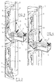
- Figures 2, 3 and 4 further show blocking device 6 of figure 1 in different positions.
- Locking body 9 Arranged in profile beam 4 on the end face is a pin 7 which is guided between two strips 8 of device 6.
- Locking body 9 is arranged on one of the strips 8 by means of a pin 10. This pin 10 is guided in a slot 11 in locking body 9. The different positions of the locking body relative to strips 8 are determined by this slot 11. Further arranged in locking body 9 is a hook part 12 which can engage on pin 7.
- Locking body 9 further has an operating surface 13.
- a spring element 14 which can engage on locking body 9.
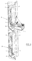
- Figure 5 shows a second embodiment 20 of the device according to the invention.
- This device 20 corresponds for the greater part with device 6 and the same parts are therefore designated with the same reference numerals.
- One of the strips 8 is guided by means of pins 21 in vertical channels.
- One of the pins 21 is connected to a spiral spring 22, whereby strip 8 is suspended resiliently in vertical direction.
- spring 22 When locking body 9 is now in blocking position, as shown, slack or extra pressure on cloth 2 can now be taken up by spring 22.
- Figure 6 shows a third embodiment 30 according to the invention. This embodiment also corresponds for the greater part with blocking device 6 and the same parts are therefore designated with the same reference numerals.
- Two blocking devices 30 are arranged in lateral guide 5 so that profile beam 4 can be blocked at two different positions.
- Arranged on locking body 9 is a second spring element 31 which extends close to hook part 12. When pin 7 now lies in the hook part, spring element 31 will then engage on pin 7. A resilient action is hereby obtained once again, whereby slack can be taken up.
- Figure 7 shows a fourth embodiment 32 of locking body 9.
- the latter is provided with a raised position 33 which defines a cavity 34 for a pressure spring 35.
- This latter presses against a stop 36 which is guided in a guide 38 of the raised position 33 by a guide cam 37.
- the pin 7 can strike against cam 37. Owing to the greater construction height of embodiment 32 the pin 7 does not have to be under spring pressure, because co-action of pin 7 with locking body 9 is now ensured.
- the beam 4 can also move up and downward to some extent and absorb tensions in cloth 2 and prevent cloth damage.
Landscapes
- Engineering & Computer Science (AREA)
- Architecture (AREA)
- Structural Engineering (AREA)
- Civil Engineering (AREA)
- Operating, Guiding And Securing Of Roll- Type Closing Members (AREA)
Abstract
- a locking body which is guided vertically between a lower position and an upper position and which in the upper position is guided horizontally between a first and second position, wherein the locking body further comprises a hook part for engaging on the pin guided in the vertical channel and wherein the locking body comprises an operating surface for operation of the locking body by the pin guided in the vertical channel in order to urge the locking body into the lower position; and
- spring means which in at least the upper position engage on the locking body in order to urge the locking body out of the first position into the second position.
Description
- The invention relates to a blocking device for blocking and unblocking a pin guided in a vertical channel.
- In sunblinds wherein a cloth is guided vertically along the window, there is arranged on the underside of the cloth a profile beam which comprises two pins, one on either side, which are guided in vertical guides. When the weather is windy, the cloth will flap back and forth, whereby the lower beam will begin to rattle in the vertical guides. It is therefore desirable to be able to secure this lower beam in the vertical guides, so that the cloth can be pulled taut and rattling is prevented.
- The above stated is an object of the invention.
- This objective is achieved with a device for blocking and unblocking a pin guided in a vertical channel, which device comprises:
- a locking body which is guided vertically between a lower position and an upper position and which in the upper position is guided horizontally between a first and second position, wherein the locking body further comprises a hook part for engaging on the pin guided in the vertical channel and wherein the locking body comprises an operating surface for operation of the locking body by the pin guided in the vertical channel in order to urge the locking body into the lower position; and
- spring means which in at least the upper position engage on the locking body in order to urge the locking body out of the first position into the second position.
- A blocking and unblocking device is obtained in particularly simple manner with a device according to the invention.
- The upper, lower, first and second positions can herein be defined by an L-shaped slot.
- In a preferred embodiment according to the invention the operating surface is arcuate. The operating surface can hereby never remain caught behind the operating surface and reliable operation of the device is ensured.
- In a preferred embodiment according to the invention the device is resiliently suspended. It can be advantageous to suspend the device resiliently so as to take up slack in for instance the cloth.
- In another embodiment according to the invention there is arranged in the hook part a spring element which likewise has the purpose of removing any slack from the cloth.
- The invention further comprises a sunblind, comprising a vertically extending cloth which can be rolled up and which on the underside is guided on either side in vertical rails, wherein at least one device according to the invention is arranged in the vertical rails to enable blocking of the underside of the cloth in the vertical rails.
- These and other features of the invention are further elucidated with reference to the annexed drawings.
- Figure 1 shows a sunblind with a blocking device according to the invention.
- Figures 2, 3 and 4 show perspective views with partly broken-away parts of the device according to the invention in different positions.
- Figure 5 shows a perspective view with partly broken-away parts of a second embodiment of a device according to the invention.
- Figures 6 and 7 each show a perspective view of other embodiments of the device according to the invention.
- Figure 1 shows in perspective view a window 1, in front of which is drawn a vertical reflective cloth 2. This cloth 2 can be rolled up into a
housing 3. Arranged on the underside of cloth 2 is aprofile beam 4 which is guided inlateral guides 5. Ablocking device 6 according to the invention is arranged inlateral guide 5 to enable blocking ofprofile beam 4 at a determined position in lateral guide and thus enable tightening of cloth 2, thereby preventing flapping during windy weather. Figures 2, 3 and 4 further show blockingdevice 6 of figure 1 in different positions. - Arranged in
profile beam 4 on the end face is apin 7 which is guided between twostrips 8 ofdevice 6. Lockingbody 9 is arranged on one of thestrips 8 by means of apin 10. Thispin 10 is guided in aslot 11 inlocking body 9. The different positions of the locking body relative tostrips 8 are determined by thisslot 11. Further arranged in lockingbody 9 is ahook part 12 which can engage onpin 7.Locking body 9 further has anoperating surface 13. - Further arranged on one of the
strips 8 is aspring element 14 which can engage on lockingbody 9. - The operation of the
device 6 according to the invention is as follows. In figure 2 thedevice 6 is shown in its rest position, whereinlocking body 9 is situated in the lower position. Whenprofile beam 4 with itspin 7 is now moved downward from above betweenstrips 8, lockingbody 9 will then be pressed aside. Whenprofile beam 4 is then moved upward again,pin 7 will then move intohook part 12 oflocking body 9 and thus carry the locking body from its lower position to its upper position (see figure 3).Spring element 14 will simultaneously engage on lockingbody 9, wherebylocking body 9 is displaced substantially horizontally from the first position to the second position. In this second position thelocking body 9 cannot slide directly to the lower position. In this position of blockingdevice 6 the reflective cloth 2 can be pulled taut. - When
profile beam 4 is then lowered again (see figure 4), the locking body will then be rotated byspring element 14 into its second position such that hookpart 12 oflocking body 9 moves out of the channel betweenstrips 8 whileoperating surface 13 moves into this channel. Whenprofile beam 4 is then moved upward once again,pin 7 will come up againstoperating surface 13 and thus movelocking body 9 to its first position and subsequently from its upper position to its lower position, whereby lockingbody 9 moves to its rest position as according to figure 2. - Figure 5 shows a
second embodiment 20 of the device according to the invention. Thisdevice 20 corresponds for the greater part withdevice 6 and the same parts are therefore designated with the same reference numerals. One of thestrips 8 is guided by means ofpins 21 in vertical channels. One of thepins 21 is connected to aspiral spring 22, wherebystrip 8 is suspended resiliently in vertical direction. When lockingbody 9 is now in blocking position, as shown, slack or extra pressure on cloth 2 can now be taken up byspring 22. - Figure 6 shows a
third embodiment 30 according to the invention. This embodiment also corresponds for the greater part withblocking device 6 and the same parts are therefore designated with the same reference numerals. Twoblocking devices 30 are arranged inlateral guide 5 so thatprofile beam 4 can be blocked at two different positions. Arranged on lockingbody 9 is asecond spring element 31 which extends close tohook part 12. Whenpin 7 now lies in the hook part,spring element 31 will then engage onpin 7. A resilient action is hereby obtained once again, whereby slack can be taken up. - Figure 7 shows a
fourth embodiment 32 oflocking body 9. The latter is provided with a raisedposition 33 which defines acavity 34 for a pressure spring 35. This latter presses against astop 36 which is guided in aguide 38 of the raisedposition 33 by aguide cam 37. Thepin 7 can strike againstcam 37. Owing to the greater construction height ofembodiment 32 thepin 7 does not have to be under spring pressure, because co-action ofpin 7 withlocking body 9 is now ensured. With thisembodiment 32 thebeam 4 can also move up and downward to some extent and absorb tensions in cloth 2 and prevent cloth damage.
Claims (6)
- Device for blocking and unblocking a pin guided in a vertical channel, which device comprises:a locking body which is guided vertically between a lower position and an upper position and which in the upper position is guided horizontally between a first and second position, wherein the locking body further comprises a hook part for engaging on the pin guided in the vertical channel and wherein the locking body comprises an operating surface for operation of the locking body by the pin guided in the vertical channel in order to urge the locking body into the lower position; andspring means which in at least the upper position engage on the locking body in order to urge the locking body out of the first position into the second position.
- Device as claimed in claim 1, wherein the upper, lower, first and second positions are defined by an L-shaped slot.
- Device as claimed in claim 1 or 2, wherein the operating surface is arcuate.
- Device as claimed in any of the foregoing claims, wherein the device is suspended resiliently.
- Device as claimed in any of the foregoing claims, wherein a spring element is arranged in the hook part.
- Sunblind, comprising a vertically extending cloth which can be rolled up and which on the underside is guided on either side in vertical rails, wherein at least one device as claimed in any of the foregoing claims is arranged in the vertical rails to enable blocking of the underside of the cloth in the vertical rails.
Applications Claiming Priority (2)
| Application Number | Priority Date | Filing Date | Title |
|---|---|---|---|
| NL1017112A NL1017112C2 (en) | 2001-01-15 | 2001-01-15 | Blocking device. |
| NL1017112 | 2001-01-15 |
Publications (1)
| Publication Number | Publication Date |
|---|---|
| EP1223262A1 true EP1223262A1 (en) | 2002-07-17 |
Family
ID=19772736
Family Applications (1)
| Application Number | Title | Priority Date | Filing Date |
|---|---|---|---|
| EP02075131A Withdrawn EP1223262A1 (en) | 2001-01-15 | 2002-01-14 | Blocking device |
Country Status (2)
| Country | Link |
|---|---|
| EP (1) | EP1223262A1 (en) |
| NL (1) | NL1017112C2 (en) |
Cited By (5)
| Publication number | Priority date | Publication date | Assignee | Title |
|---|---|---|---|---|
| WO2004048715A1 (en) * | 2002-11-22 | 2004-06-10 | Llaza, Sa | Vertical awning comprising an automatic device for the taut fixing thereof in the partially or totally extended position |
| EP2441913A1 (en) | 2010-10-15 | 2012-04-18 | Somfy SAS | Device for blocking a load bar of a screen and closing or sun-protection installation provided with such a blocking device |
| AU2013270515B2 (en) * | 2011-07-21 | 2016-01-21 | Uniline Australia Limited | An Improved Awning System and Components Therefor |
| ITUB20156296A1 (en) * | 2015-12-04 | 2017-06-04 | Gibus Spa | WRAPPING TENT |
| DE102019006789A1 (en) * | 2019-09-27 | 2021-04-01 | Stobag Ag | Shading device |
Citations (1)
| Publication number | Priority date | Publication date | Assignee | Title |
|---|---|---|---|---|
| EP0957230A1 (en) * | 1998-05-12 | 1999-11-17 | Mado Nederland B.V. | A method for securing the cloth of a screen device |
-
2001
- 2001-01-15 NL NL1017112A patent/NL1017112C2/en not_active IP Right Cessation
-
2002
- 2002-01-14 EP EP02075131A patent/EP1223262A1/en not_active Withdrawn
Patent Citations (1)
| Publication number | Priority date | Publication date | Assignee | Title |
|---|---|---|---|---|
| EP0957230A1 (en) * | 1998-05-12 | 1999-11-17 | Mado Nederland B.V. | A method for securing the cloth of a screen device |
Cited By (6)
| Publication number | Priority date | Publication date | Assignee | Title |
|---|---|---|---|---|
| WO2004048715A1 (en) * | 2002-11-22 | 2004-06-10 | Llaza, Sa | Vertical awning comprising an automatic device for the taut fixing thereof in the partially or totally extended position |
| EP2441913A1 (en) | 2010-10-15 | 2012-04-18 | Somfy SAS | Device for blocking a load bar of a screen and closing or sun-protection installation provided with such a blocking device |
| AU2013270515B2 (en) * | 2011-07-21 | 2016-01-21 | Uniline Australia Limited | An Improved Awning System and Components Therefor |
| ITUB20156296A1 (en) * | 2015-12-04 | 2017-06-04 | Gibus Spa | WRAPPING TENT |
| DE102019006789A1 (en) * | 2019-09-27 | 2021-04-01 | Stobag Ag | Shading device |
| US12281476B2 (en) | 2019-09-27 | 2025-04-22 | Stobag Ag | Shading device |
Also Published As
| Publication number | Publication date |
|---|---|
| NL1017112C2 (en) | 2002-07-16 |
Similar Documents
| Publication | Publication Date | Title |
|---|---|---|
| KR101272517B1 (en) | Active hood device for vehicle | |
| EP2607125B1 (en) | Locking mechanism for open roof construction and open roof construction provided therewith | |
| KR20150002545A (en) | Shading device for a glass surface region of a motor vehicle | |
| US4394044A (en) | Removable sunroof for vehicles | |
| JPH0322323B2 (en) | ||
| EP1911620B1 (en) | Shading system for a transparent area of an automotive vehicle roof, and automotive vehicle | |
| CA2565462A1 (en) | Head rail and support bracket | |
| KR101724120B1 (en) | A horizontal sliding door with Length variable type weather strip | |
| EP3162604A1 (en) | Deflector device for vehicle | |
| US20060049671A1 (en) | Sliding roof system | |
| EP3181800B1 (en) | Universal automatic tensioning system for roller blinds and awnings with side rails | |
| US3005489A (en) | Combination window and roller screen assembly | |
| NL1017112C2 (en) | Blocking device. | |
| US4226455A (en) | Locking device for raisable venetian blind | |
| CN218092579U (en) | Sliding window and engineering machinery cab | |
| KR101219396B1 (en) | Interlock type roll blind apparatus of panorama sunroof | |
| KR101807123B1 (en) | Door curtain assembly for vehicle | |
| KR101275165B1 (en) | Sunroof Mounting Device | |
| JP7699270B1 (en) | Sunshade Device | |
| JPH037506Y2 (en) | ||
| JPS5976384A (en) | Window glass guide of height adjustable window glass in vehicle | |
| KR200488580Y1 (en) | Shading device for vehicle door | |
| EP1270865A2 (en) | Sunblind | |
| CN216969295U (en) | Skylight sunshade screen guide structure and car | |
| CN214523293U (en) | Sunshade and mechanical equipment |
Legal Events
| Date | Code | Title | Description |
|---|---|---|---|
| PUAI | Public reference made under article 153(3) epc to a published international application that has entered the european phase |
Free format text: ORIGINAL CODE: 0009012 |
|
| AK | Designated contracting states |
Kind code of ref document: A1 Designated state(s): AT BE CH CY DE DK ES FI FR GB GR IE IT LI LU MC NL PT SE TR |
|
| AX | Request for extension of the european patent |
Free format text: AL;LT;LV;MK;RO;SI |
|
| 17P | Request for examination filed |
Effective date: 20030117 |
|
| AKX | Designation fees paid |
Designated state(s): AT BE CH CY DE DK ES FI FR GB GR IE IT LI LU MC NL PT SE TR |
|
| 17Q | First examination report despatched |
Effective date: 20061212 |
|
| STAA | Information on the status of an ep patent application or granted ep patent |
Free format text: STATUS: THE APPLICATION IS DEEMED TO BE WITHDRAWN |
|
| 18D | Application deemed to be withdrawn |
Effective date: 20070623 |