EP1223090A2 - Seat belt device - Google Patents
Seat belt device Download PDFInfo
- Publication number
- EP1223090A2 EP1223090A2 EP02090009A EP02090009A EP1223090A2 EP 1223090 A2 EP1223090 A2 EP 1223090A2 EP 02090009 A EP02090009 A EP 02090009A EP 02090009 A EP02090009 A EP 02090009A EP 1223090 A2 EP1223090 A2 EP 1223090A2
- Authority
- EP
- European Patent Office
- Prior art keywords
- switch
- drive
- gear
- actuating unit
- mode
- Prior art date
- Legal status (The legal status is an assumption and is not a legal conclusion. Google has not performed a legal analysis and makes no representation as to the accuracy of the status listed.)
- Granted
Links
Images

Classifications
-
- B—PERFORMING OPERATIONS; TRANSPORTING
- B60—VEHICLES IN GENERAL
- B60R—VEHICLES, VEHICLE FITTINGS, OR VEHICLE PARTS, NOT OTHERWISE PROVIDED FOR
- B60R22/00—Safety belts or body harnesses in vehicles
- B60R22/34—Belt retractors, e.g. reels
- B60R22/46—Reels with means to tension the belt in an emergency by forced winding up
-
- B—PERFORMING OPERATIONS; TRANSPORTING
- B60—VEHICLES IN GENERAL
- B60R—VEHICLES, VEHICLE FITTINGS, OR VEHICLE PARTS, NOT OTHERWISE PROVIDED FOR
- B60R22/00—Safety belts or body harnesses in vehicles
- B60R22/34—Belt retractors, e.g. reels
- B60R22/44—Belt retractors, e.g. reels with means for reducing belt tension during use under normal conditions
- B60R2022/4473—Belt retractors, e.g. reels with means for reducing belt tension during use under normal conditions using an electric retraction device
-
- B—PERFORMING OPERATIONS; TRANSPORTING
- B60—VEHICLES IN GENERAL
- B60R—VEHICLES, VEHICLE FITTINGS, OR VEHICLE PARTS, NOT OTHERWISE PROVIDED FOR
- B60R22/00—Safety belts or body harnesses in vehicles
- B60R22/34—Belt retractors, e.g. reels
- B60R22/46—Reels with means to tension the belt in an emergency by forced winding up
- B60R2022/4666—Reels with means to tension the belt in an emergency by forced winding up characterised by electric actuators
Definitions
- the invention relates to a seat belt device for motor vehicles with a seat belt, a belt retractor and a drive for the Retractor.
- Such seat belt devices are generally known. through the drive can, for example, implement a belt tensioning function are driven in the winding direction in the event of an accident to ensure that the belt is tight on the body in good time of the respective vehicle occupant.
- a transmission between the drive and the reel and a switch are provided, with the switch starting from a freewheeling mode, at least one transmission configuration is adjustable, which is a comfort mode with driven in the unwinding direction Rewinder and / or a pretensioner mode with in the winding direction driven reel corresponds, and the switch by means of of the drive can be actuated and with the same drive direction of the drive different switch positions are adjustable.
- the seat belt device can at least two operating modes are operated, namely in a freewheeling mode and in at least one drive mode.
- the freewheel mode enables normal use of the seat belt in normal operation of the Vehicle in which the reel is freely rotatable. Is it the Drive mode around the comfort mode, so the drive ensures an automatic Unwinding the belt to make the vehicle occupant take off the belt or at the beginning of driving the belt to hand over to the vehicle occupants. If it is in the drive mode on the other hand, is the pretensioner mode, then the belt by means of the drive on the reel, e.g. a belt tensioning function to realize.
- the comfort mode and / or the tensioning mode can be used can be set by means of a switch which can be actuated by the drive is.
- a non-positive connection can thus be made by means of the switch between the drive and the reel via the gearbox become. Since the switch can be operated by means of the drive, the drive automatically takes care of the production of the desired one positive connection.
- different transmission configurations can be set are one of which is the comfort mode and another the penalty mode corresponds so that the device operates in three operating modes can be.
- the comfort mode By selecting a switch position you can choose between the at least with regard to the direction of rotation and preferably also with regard to the rotation speed of the reel different drive modes and thus you can choose between comfort mode and tension mode. According to the invention, this does not require the drive direction of the Drive to be respected. An electric motor, if provided the drive therefore needs to switch between freewheeling mode and not being reversed in comfort mode.
- the transmission and the switch are designed such that different with the same drive direction of the drive by means of the switch Direction of rotation of the reel and / or different Gear ratios of the transmission are adjustable.
- the selection of the respective drive mode can depend on the mode of operation of the drive.
- selectable switch positions by means of the drive the course of a control signal for an electric motor of the drive are dependent, in particular on the course of a start pulse of the control signal.
- the control signals provided for the selection of different switch positions can, for example, immediately with regard to a maximum value differentiate after the signal generation.
- a pronounced start pulse should be provided so that the initial signal level above a signal level used in the subsequent continuous operation lies. It can therefore be a more or less sharp starting impulse are generated, which is characteristic of the desired switch position is and from the switch or from an actuator for the Switches can be distinguished from other start signals.
- the switch has a pivoted shift lever includes, switch positions selectable by means of the drive the pivoting direction of the shift lever are dependent.
- the switch can be based on one corresponding to the freewheeling mode Freewheel position can be pivoted by means of the drive, whereby a gear configuration is specified by the pivoting direction is that of the switch position achievable by pivoting equivalent.
- the switch can be controlled via an actuating unit is for transmitting a starting torque of the drive and preferably also following a starting torque transmission for transmission a preferably approximately constant holding force on the switch is, the actuating unit due to a recoil moment of the starting torque is movable.
- the actuation unit works on the recoil principle. In this way the starting torque of the drive is used to to operate the switch.
- the actuating unit has a drive shaft at least in some areas of the drive unit, in particular coaxially surrounds and is rotatable relative to the drive unit.
- the actuation unit can be connected to the drive unit which is activated when the Drive is set in rotation, interact so that the starting drive unit on the actuator repels, so that Actuator in motion in the opposite direction is and this counter-movement in a switching movement of the switch can be implemented.
- the actuating unit comprises a cam control with which the Switch is acted upon.
- the actuating unit preferably has at least two as cams one Cam control serving control sections with which the Switch can be acted on in different ways.
- control sections of the actuator for Transfer of opposite torques to the switch are. With the same drive direction of the drive, the switch thus pivoted in different directions via the actuating unit become.
- a starting torque of the drive of the switch either only by one Control section or acted upon successively by two control sections can be. It is preferred if from a predeterminable Magnitude of the starting torque of a control section that first acts on the switch can be overridden by a subsequent control section.
- the first control section can be applied when the Switch compliant to the second control section and in particular by using the second control section on the Switch transmissible torque can be deformed elastically.
- the transmission includes a planetary gear, the reel as a Ring gear of the planetary gear is formed.
- a sun gear of the planetary gear rotatably connected to the drive.
- a freewheeling mode is enabled Freewheel part of the transmission is provided as a planet carrier is trained.
- the switch preferably interacts with the transmission in such a way that after actuation of the switch depending on the switch position the freewheel part of the gearbox either held by the switch or is coupled to the drive.
- the transmission comprises a planetary gear
- it can be used in particular for the comfort mode synchronized with the drive freewheel part rotate with the sun gear formed by the drive and an as Ring gear trained reel over the planet gears in the same Direction as the sun gear is turned.
- the drive of the reel thus takes place by a circular movement of the planet gears around a central one Rotation axis of the drive and the gear.
- FIGS Subclaims Further preferred embodiments of the invention are also shown in FIGS Subclaims, the description and the drawing.
- the seat belt device comprises a drive 19 by an electric motor 31 with a drive shaft 33 and a Belt drive with a drive belt 75 and a pulley 77 is formed.
- the drive belt 75 is preferably designed as a toothed belt.
- a belt retractor 15 is optionally in a unwinding direction 1 or a winding direction 2 driven to a seat belt 11 either in a comfort mode or in to wind up in a penalty mode.
- the pulley 77 can also be used as a drive pulley or drive wheel.
- the axis of rotation of the reel-up 15 coincides with the central axis of rotation 59 of the Gear 23 and the drive wheel 77 together and runs parallel offset to drive axis 57 of motor 31.
- the reel 15 is designed as a ring gear of the gear 23 and over the planet gears 39 can be driven.
- a freewheel part 37 of the transmission 23 designed as a planet gear carrier coupled.
- the freewheel part 37 is over the Planet gears 39 together with the reel 15 relative to the sun gear 35 rotatable.
- the freewheel part 37 thus enables a freewheeling mode Contraption.
- the switch 27 includes a pivotable mounted shift lever 51.
- the pivot axis 55 of the shift lever 51st runs parallel to the central axis of rotation 59.
- the multi-arm shift lever 51 is by means of a return spring 47 with the drive 19 switched off in a freewheeling mode Neutral or freewheeling position held in the Shift lever 51 is out of engagement with the gear 23.
- the part of the shift lever 51 which interacts with the transmission 23 is bow-shaped and includes two lever arms, the free ends are designed as engagement sections 63a, 63b. With the engagement sections 63a, 63b, the shift lever 51 can be pivoted out of the Engage the freewheel position in axially spaced engagement areas 67a, 67b, which are formed on the outer circumference of the freewheel part 37.
- a holding area 67a over which the freewheel part 37 by means of the shift lever 51 can be prevented from rotating includes a variety of holding receptacles 65 arranged distributed in the circumferential direction, the respective radially protruding projections of the holding area 67a are limited.
- One on the side of the pulley 77 facing the Holding area 67a located coupling area 67b comprises a toothing, so that the freewheel part 37 is formed as a gear in this area is.
- One on the outer periphery of the pulley 77 axially spaced from the belt area trained engagement area 79 for the shift lever 51 comprises also a gearing.
- the engaging portions 63a, 63b of the shift lever 51 are different formed engagement areas 67a, 67b of the freewheel part 37 customized.
- a holding section 63a can be inserted into the holding receptacles 65, to hold the freewheel member 37 while with a coupling portion 63b a non-positive connection between the pulley 77 and the freewheel part 37 can be produced.
- the holding section 63a comprises a holding tooth 81
- the Coupling section 63b two rotatably mounted on the shift lever 51 and Coupling gear wheels 83 connected to one another in a rotationally fixed manner.
- the gear wheels 83 can also be used with friction wheels engagement areas of the pulley 77 designed as friction surfaces or the freewheel part 37 cooperate. It is also possible instead two separate wheels 83 a single one, e.g. cylindrical gear or Provide friction wheel, the axial length of which is dimensioned such that it bridge the axial distance between the engagement areas 79, 67b can.
- the shift lever 51 In the freewheel mode, the shift lever 51 is in the neutral position.
- the reel 15 is freely rotatable in both directions, since the freewheel part 37 of the gear 23, which roll through on the sun gear 35 Planet gears 39 is set in rotation, also rotate freely can.
- the switch 27 is actuated via an actuation unit 71, with which a starting torque of the engine 31 is transmitted to the shift lever 51 can be.
- the actuator 71 includes one below Cam control 85 described in more detail, which rotatably on a cylindrical Outer body 91 is attached to the drive shaft 33 of the motor 31 coaxially surrounds.
- the outer body 91 acts with the drive shaft 33 or the drive shaft 33 comprehensive drive unit 53 such that the drive shaft set in rotation by switching on the motor 31 33 or drive unit 53 on the outer body 91. hereby becomes the outer body 91 in the direction of rotation of the drive shaft 33 rotated in the opposite direction. This is due to the starting torque of the engine 31 recoil torque causes the cam control to rotate 85 of the actuator 71. This by utilizing the Recoil principle achieved movement of the cam controller 85 becomes Operation of the shift lever 51 used.
- the cam control 85 has two in different angular directions radially from a ring portion 93 surrounding the outer body 91 Cam control 85 projecting cams 87, 89.
- the cams 87, 89 serve as control sections with which the shift lever 51 to different Is acted upon.
- a cam or control section 87 is an elastically deformable bending strip formed with one end in a recess of the Ring section 93 is attached and the other end to the shift lever 51 can attack, in the embodiment shown (cf. 1b) with a bent end portion on one of the shift lever 51st protruding pin 95.
- the other control section 89 is rigidly connected to the ring section 93 Cam formed, which when rotating the ring portion 93rd cooperates with a stop surface 97 of the shift lever 51.
- the size of the starting torque of the motor 31 decides whether the Shift lever 51 only by means of the bending strip 87 in one direction is pivoted or the rigid cam 89 asserts itself by the resilient bending strip 87 overridden and the shift lever 51 in the other direction is pivoted.
- the rigid cam arrives from a predeterminable size of the starting torque 89 overcoming an insurmountable one if the starting torque is too low Switching resistance of the switch in engagement with the stop surface 97 and is able to shift lever 51 by deforming the bending strip 87 to pivot.
- the switch position can consequently be changed by the starting behavior of the motor 31 of the switch 27 and thus the desired transmission configuration can be set by means of the switch 27, whereupon is discussed in more detail below.
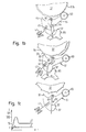
- FIG. 1c One possibility, the starting behavior of the motor 31 and thus that Influencing switching behavior is indicated schematically in FIG. 1c. It an application example is shown, in which during continuous operation following a start phase of the engine 31 in comfort mode a current of the order of magnitude 1 A and a current in the penalty mode of the order of 10 A flows.
- a start pulse is generated during the start phase, whose maximum value is of the order of magnitude at 100 A and is significant from the start section of the intended for comfort mode Control signal differs.
- the continuous operating value can also be in comfort mode exceeding start pulse are generated, but its maximum value is significantly smaller than that generated in the penalty mode Start pulse.
- the start sections of the control signals are in comfort mode and in Pretensioner mode selected so that the respective starting torque corresponding recoil moments for when pivoting the Switch lever 51 each sufficiently large resistances to be overcome are.
- the recoil moment is sufficient in comfort mode not to pivot the shift lever 51 by means of the rigid cam 89, but the shift lever 51 is only by means of the bending strip 87 rotated.
- FIG. 1b shows how the shift lever in comfort mode 51 is pivoted by means of the bending strip 87 to the coupling gears 83 at the free end of a lever arm of the shift lever 51 in Engagement with the teeth 67b of the freewheel member 37 and the teeth 79 to bring the pulley 77.
- the stiffness of the bending strip 87 is chosen large enough to deflect the return spring 47 to be able to.
- Fig. 1b shows how large enough Recoil moment of the rigid cam 89 deforming the bending strip 87 rotates the shift lever 51 in the other direction around the retaining tooth 81 of the other lever arm of the shift lever 51 in one of the holding receptacles 65 of the other engagement area 67a of the freewheel part 37.
- the return spring 47 is deflected in the other direction.
- the return spring 47 ensures that that the shift lever 51 is pivoted back into the neutral position in which freely rotate the freewheel part 37 relative to the shift lever 51 can.
- the coupling between the drive shaft 33 and the drive unit 53 on the one hand and the outer body 91 carrying the ring section 93 on the other hand is designed such that when the engine 31 is running, the shift lever 51 via the actuation unit 71 - in comfort mode via the bending strip 87 and in the penalty mode over the rigid cam 89 - in the Switch position previously set by the recoil moment is and after switching off the motor 31, the return spring 47 Switch lever 51 can pivot back into the neutral position. The freewheel mode thus adjusts itself again.
- the freewheel part 37 and the sun gear 35 are through the gears 83 of the shift lever 51 synchronized, so that the Sun gear 35 and the freewheel member 37 in the same direction and with the turn at the same speed.
- the retractor 15 is driven thus by the orbital movement of the planet gears carried by the freewheel part 37 39 about the central axis of rotation 59, with a through the belt drive predetermined gear ratio, preferably is about 7: 1.
- the freewheel part 37 is by the shift lever 51 prevented from rotating so that the drive of the reel 15 by the rotation of the planet gears driven by the sun gear 35 39 takes place.
- the gear ratio of the drive 19 of approximately 7: 1 overall between the drive shaft 33 of the motor 31 and the reel 15 a gear ratio of about 25: 1.
- the belt 11 in Pretensioner mode is thus wound up much faster than it is in comfort mode is handled.
Landscapes
- Engineering & Computer Science (AREA)
- Mechanical Engineering (AREA)
- Transmission Devices (AREA)
- Automotive Seat Belt Assembly (AREA)
Abstract
Description
Die Erfindung betrifft eine Sicherheitsgurtvorrichtung für Kraftfahrzeuge mit einem Sicherheitsgurt, einem Gurtaufroller und einem Antrieb für den Aufroller.The invention relates to a seat belt device for motor vehicles with a seat belt, a belt retractor and a drive for the Retractor.
Derartige Sicherheitsgurtvorrichtungen sind grundsätzlich bekannt. Mittels des Antriebs kann beispielsweise eine Gurtstrafffunktion realisiert werden, indem bei einem Unfall der Aufroller in Aufwickelrichtung angetrieben wird, um dafür zu sorgen, daß der Gurt rechtzeitig eng am Körper des jeweiligen Fahrzeuginsassen anliegt.Such seat belt devices are generally known. through the drive can, for example, implement a belt tensioning function are driven in the winding direction in the event of an accident to ensure that the belt is tight on the body in good time of the respective vehicle occupant.
Es ist eine Aufgabe der Erfindung, eine Sicherheitsgurtvorrichtung der eingangs genannten Art zu schaffen, die bei möglichst einfachem Aufbau sowie sicherer und zuverlässiger Funktionsweise möglichst vielseitig einsetzbar ist.It is an object of the invention to provide a seat belt device to create the type mentioned, with the simplest possible structure as well as safe and reliable functionality as versatile as possible is.
Die Lösung dieser Aufgabe erfolgt durch die Merkmale des Anspruchs 1 und insbesondere dadurch, daß ein Getriebe zwischen dem Antrieb und dem Aufroller sowie ein Schalter vorgesehen sind, wobei mit dem Schalter ausgehend von einem Freilaufmodus wenigstens eine Getriebekonfiguration einstellbar ist, die einem Komfortmodus mit in Abwickelrichtung angetriebenem Aufroller und/oder einem Straffermodus mit in Aufwickelrichtung angetriebenem Aufroller entspricht, und wobei der Schalter mittels des Antriebs betätigbar ist und bei gleicher Antriebsrichtung des Antriebs verschiedene Schalterstellungen einstellbar sind. This object is achieved by the features of claim 1 and in particular in that a transmission between the drive and the reel and a switch are provided, with the switch starting from a freewheeling mode, at least one transmission configuration is adjustable, which is a comfort mode with driven in the unwinding direction Rewinder and / or a pretensioner mode with in the winding direction driven reel corresponds, and the switch by means of of the drive can be actuated and with the same drive direction of the drive different switch positions are adjustable.
Die erfindungsgemäße Sicherheitsgurtvorrichtung kann in wenigstens zwei Betriebsmodi betrieben werden, und zwar in einem Freilaufmodus und in zumindest einem Antriebsmodus. Der Freilaufmodus ermöglicht eine normale Benutzung des Sicherheitsgurtes im Normalbetrieb des Fahrzeugs, in dem der Aufroller frei drehbar ist. Handelt es sich bei dem Antriebsmodus um den Komfortmodus, so sorgt der Antrieb für ein automatisches Abwickeln des Gurtes, um dem Fahrzeuginsassen das Ausziehen des Gurtes zu erleichtern oder zu Beginn des Fahrbetriebs den Gurt an den Fahrzeuginsassen heranzureichen. Wenn es sich bei dem Antriebsmodus dagegen um den Straffermodus handelt, dann wird der Gurt mittels des Antriebs auf dem Aufroller aufgewickelt, um z.B. eine Gurtstrafffunktion zu realisieren.The seat belt device according to the invention can at least two operating modes are operated, namely in a freewheeling mode and in at least one drive mode. The freewheel mode enables normal use of the seat belt in normal operation of the Vehicle in which the reel is freely rotatable. Is it the Drive mode around the comfort mode, so the drive ensures an automatic Unwinding the belt to make the vehicle occupant take off the belt or at the beginning of driving the belt to hand over to the vehicle occupants. If it is in the drive mode on the other hand, is the pretensioner mode, then the belt by means of the drive on the reel, e.g. a belt tensioning function to realize.
Der Komfortmodus und/oder der Straffermodus können erfindungsgemäß mittels eines Schalters eingestellt werden, der durch den Antrieb betätigbar ist. Mittels des Schalters kann somit eine kraftschlüssige Verbindung zwischen dem Antrieb und dem Aufroller über das Getriebe hergestellt werden. Indem der Schalter mittels des Antriebs betätigt werden kann, sorgt der Antrieb automatisch selbst für die Herstellung der jeweils gewünschten kraftschlüssigen Verbindung.According to the invention, the comfort mode and / or the tensioning mode can be used can be set by means of a switch which can be actuated by the drive is. A non-positive connection can thus be made by means of the switch between the drive and the reel via the gearbox become. Since the switch can be operated by means of the drive, the drive automatically takes care of the production of the desired one positive connection.
Erfindungsgemäß ist lediglich eine einzige Antriebsrichtung des Antriebs erforderlich, um verschiedene Schalterstellungen einstellen zu können. Bei Verwendung eines Elektromotors für den Antrieb braucht somit das Vorzeichen eines Ansteuersignals für den Elektromotor nicht geändert zu werden, d.h. der Elektromotor braucht nicht mit unterschiedlichen Polaritäten betrieben, d.h. nicht umgepolt zu werden, um die verschiedenen Schalterstellungen einstellen zu können.According to the invention, only a single drive direction of the drive is required to be able to set different switch positions. When using an electric motor for the drive, this is what is needed Sign of a control signal for the electric motor is not changed to become, i.e. the electric motor does not need different polarities operated, i.e. not to be reversed to the different To be able to set switch positions.
Bevorzugt ist es, wenn verschiedene Getriebekonfigurationen einstellbar sind, von denen eine dem Komfortmodus und eine andere dem Straffermodus entspricht, so daß die Vorrichtung in drei Betriebsmodi betrieben werden kann. Durch Auswahl einer Schalterstellung kann zwischen den zumindest hinsichtlich der Drehrichtung und bevorzugt auch hinsichtlich der Drehgeschwindigkeit des Aufrollers verschiedenen Antriebsmodi und somit zwischen dem Komfortmodus und dem Straffermodus gewählt werden. Hierbei braucht erfindungsgemäß nicht auf die Antriebsrichtung des Antriebs geachtet zu werden. Ein gegebenenfalls vorgesehener Elektromotor des Antriebs braucht daher zum Umschalten zwischen dem Freilaufmodus und dem Komfortmodus nicht umgepolt zu werden.It is preferred if different transmission configurations can be set are one of which is the comfort mode and another the penalty mode corresponds so that the device operates in three operating modes can be. By selecting a switch position you can choose between the at least with regard to the direction of rotation and preferably also with regard to the rotation speed of the reel different drive modes and thus you can choose between comfort mode and tension mode. According to the invention, this does not require the drive direction of the Drive to be respected. An electric motor, if provided the drive therefore needs to switch between freewheeling mode and not being reversed in comfort mode.
Vorzugsweise sind das Getriebe und der Schalter derart ausgebildet, daß bei gleicher Antriebsrichtung des Antriebs mittels des Schalters unterschiedliche Drehrichtungen des Aufrollers und/oder unterschiedliche Übersetzungsverhältnisse des Getriebes einstellbar sind.Preferably, the transmission and the switch are designed such that different with the same drive direction of the drive by means of the switch Direction of rotation of the reel and / or different Gear ratios of the transmission are adjustable.
Bei gleicher Antriebsrichtung kann z.B. im Komfortmodus zum Abwickeln des Gurtes für ein vergleichsweise niedriges Übersetzungsverhältnis gesorgt werden, während zum Aufwickeln des Gurtes im Straffermodus ein relativ hohes Übersetzungsverhältnis realisiert werden kann.With the same drive direction, e.g. in comfort mode for unwinding of the belt for a comparatively low gear ratio be while in the pretensioner mode for winding the belt relatively high gear ratio can be realized.
Die Auswahl des jeweiligen Antriebsmodus kann durch die Betriebsweise des Antriebs getroffen werden. The selection of the respective drive mode can depend on the mode of operation of the drive.
So können gemäß einem bevorzugten Ausführungsbeispiel der Erfindung mittels des Antriebs auswählbare Schalterstellungen von der Größe eines Startmoments des Antriebs abhängig sein. Hierbei wird das Anlaufverhalten des Antriebs ausgenutzt, um zwischen den auswählbaren Schalterstellungen zu unterscheiden.So according to a preferred embodiment of the invention switch positions of the size of a selectable by means of the drive The starting torque of the drive. This is the startup behavior of the drive to switch between the selectable switch positions to distinguish.
In einer bevorzugten praktischen Ausgestaltung der Erfindung wird vorgeschlagen, daß mittels des Antriebs auswählbare Schalterstellungen von dem Verlauf eines Ansteuersignals für einen Elektromotor des Antriebs abhängig sind, insbesondere von dem Verlauf eines Startimpulses des Ansteuersignals.In a preferred practical embodiment of the invention, it is proposed that that selectable switch positions by means of the drive the course of a control signal for an electric motor of the drive are dependent, in particular on the course of a start pulse of the control signal.
Die zur Auswahl verschiedener Schalterstellungen vorgesehenen Ansteuersignale können sich beispielsweise hinsichtlich eines Maximalwerts unmittelbar im Anschluß an die Signalerzeugung unterscheiden. Zumindest für einen Antriebsmodus, insbesondere für den Straffermodus, kann ein ausgeprägter Startimpuls vorgesehen sein, so daß die anfängliche Signalhöhe oberhalb einer im anschließenden Dauerbetrieb verwendeten Signalhöhe liegt. Es kann folglich ein mehr oder weniger scharfer Startimpuls erzeugt werden, der für die jeweils gewünschte Schalterstellung charakteristisch ist und vom Schalter oder von einer Betätigungseinheit für den Schalter jeweils von anderen Startsignalen unterschieden werden kann.The control signals provided for the selection of different switch positions can, for example, immediately with regard to a maximum value differentiate after the signal generation. At least for a drive mode, in particular for the pretensioning mode, a pronounced start pulse should be provided so that the initial signal level above a signal level used in the subsequent continuous operation lies. It can therefore be a more or less sharp starting impulse are generated, which is characteristic of the desired switch position is and from the switch or from an actuator for the Switches can be distinguished from other start signals.
Auf diese Weise können unterscheidbare Startszenarien realisiert werden, so daß in Abhängigkeit von dem jeweiligen Startszenario die entsprechende Schalterstellung erreicht und damit eine gewünschte Getriebekonfiguration eingestellt werden kann. In this way, distinguishable start scenarios can be realized so that depending on the respective start scenario the corresponding one Switch position reached and thus a desired gear configuration can be adjusted.
Gemäß einem weiteren bevorzugten Ausführungsbeispiel der Erfindung ist vorgesehen, daß der Schalter einen schwenkbar gelagerten Schalthebel umfaßt, wobei mittels des Antriebs auswählbare Schalterstellungen von der Schwenkrichtung des Schalthebels abhängig sind.According to a further preferred embodiment of the invention provided that the switch has a pivoted shift lever includes, switch positions selectable by means of the drive the pivoting direction of the shift lever are dependent.
Hierbei kann der Schalter ausgehend von einer dem Freilaufmodus entsprechenden Freilaufstellung mittels des Antriebs verschwenkt werden, wobei durch die Schwenkrichtung eine Getriebekonfiguration vorgegeben ist, die der durch das Verschwenken jeweils erreichbaren Schalterstellung entspricht.Here, the switch can be based on one corresponding to the freewheeling mode Freewheel position can be pivoted by means of the drive, whereby a gear configuration is specified by the pivoting direction is that of the switch position achievable by pivoting equivalent.
Gemäß einer weiteren bevorzugten Ausführungsform der Erfindung ist vorgesehen, daß der Schalter über eine Betätigungseinheit ansteuerbar ist, die zur Übertragung eines Startmoments des Antriebs und vorzugsweise außerdem im Anschluß an eine Startmomentübertragung zur Übertragung einer bevorzugt etwa konstanten Haltekraft auf den Schalter ausgebildet ist, wobei die Betätigungseinheit durch ein Rückstoßmoment aufgrund des Startmoments bewegbar ist.According to a further preferred embodiment of the invention provided that the switch can be controlled via an actuating unit is for transmitting a starting torque of the drive and preferably also following a starting torque transmission for transmission a preferably approximately constant holding force on the switch is, the actuating unit due to a recoil moment of the starting torque is movable.
Die Betätigungseinheit arbeitet in dieser Variante nach dem Rückstoßprinzip. Auf diese Weise wird das Startmoment des Antriebs dazu genutzt, den Schalter zu betätigen.In this variant, the actuation unit works on the recoil principle. In this way the starting torque of the drive is used to to operate the switch.
In einer bevorzugten praktischen Ausgestaltung der Erfindung ist vorgesehen, daß die Betätigungseinheit wenigstens bereichsweise eine eine Antriebswelle des Antriebs umfassende Antriebseinheit insbesondere koaxial umgibt und gegenüber der Antriebseinheit verdrehbar ist. In a preferred practical embodiment of the invention, that the actuating unit has a drive shaft at least in some areas of the drive unit, in particular coaxially surrounds and is rotatable relative to the drive unit.
Die Betätigungseinheit kann mit der Antriebseinheit, die beim Start des Antriebs in Drehung versetzt wird, derart zusammenwirken, daß sich die startende Antriebseinheit an der Betätigungseinheit abstößt, so daß die Betätigungseinheit in die entgegengesetzte Richtung in Bewegung gesetzt wird und diese Gegenbewegung in eine Schaltbewegung des Schalters umgesetzt werden kann.The actuation unit can be connected to the drive unit which is activated when the Drive is set in rotation, interact so that the starting drive unit on the actuator repels, so that Actuator in motion in the opposite direction is and this counter-movement in a switching movement of the switch can be implemented.
Eine weitere bevorzugte Ausführungsform der Erfindung schlägt vor, daß die Betätigungseinheit eine Nockensteuerung umfaßt, mit welcher der Schalter beaufschlagbar ist.Another preferred embodiment of the invention proposes that the actuating unit comprises a cam control with which the Switch is acted upon.
Vorzugsweise weist die Betätigungseinheit wenigstens zwei als Nocken einer Nockensteuerung dienende Steuerabschnitte auf, mit denen der Schalter auf unterschiedliche Weise beaufschlagbar ist.The actuating unit preferably has at least two as cams one Cam control serving control sections with which the Switch can be acted on in different ways.
Dabei ist insbesondere gemäß einer weiteren Ausführungsform der Erfindung vorgesehen, daß die Steuerabschnitte der Betätigungseinheit zur Übertragung von entgegengesetzten Drehmomenten auf den Schalter ausgebildet sind. Bei gleicher Antriebsrichtung des Antriebs kann der Schalter somit über die Betätigungseinheit in unterschiedliche Richtungen verschwenkt werden.In particular, according to a further embodiment of the invention provided that the control sections of the actuator for Transfer of opposite torques to the switch are. With the same drive direction of the drive, the switch thus pivoted in different directions via the actuating unit become.
Des weiteren ist bevorzugt vorgesehen, daß in Abhängigkeit von der Größe eines Startmoments des Antriebs der Schalter entweder nur durch einen Steuerabschnitt oder nacheinander durch zwei Steuerabschnitte beaufschlagt werden kann. Dabei ist es bevorzugt, wenn ab einer vorgebbaren Größe des Startmoments ein den Schalter zuerst beaufschlagender Steuerabschnitt durch einen nachfolgenden Steuerabschnitt übersteuerbar ist. Furthermore, it is preferably provided that depending on the size a starting torque of the drive of the switch either only by one Control section or acted upon successively by two control sections can be. It is preferred if from a predeterminable Magnitude of the starting torque of a control section that first acts on the switch can be overridden by a subsequent control section.
Der erste Steuerabschnitt kann bei gemeinsamer Beaufschlagung des Schalters dem zweiten Steuerabschnitt gegenüber nachgiebig ausgebildet und insbesondere durch ein mit dem zweiten Steuerabschnitt auf den Schalter übertragbares Drehmoment elastisch verformbar sein.The first control section can be applied when the Switch compliant to the second control section and in particular by using the second control section on the Switch transmissible torque can be deformed elastically.
In einer besonders bevorzugten praktischen Ausgestaltung der Erfindung umfaßt das Getriebe ein Planetengetriebe, wobei der Aufroller als ein Hohlrad des Planetengetriebes ausgebildet ist. Vorzugsweise ist ein Sonnenrad des Planetengetriebes drehfest mit dem Antrieb verbunden. Des weiteren ist vorzugsweise vorgesehen, daß ein den Freilaufmodus ermöglichendes Freilaufteil des Getriebes vorgesehen ist, das als Planetenradträger ausgebildet ist.In a particularly preferred practical embodiment of the invention the transmission includes a planetary gear, the reel as a Ring gear of the planetary gear is formed. Preferably is a sun gear of the planetary gear rotatably connected to the drive. Of it is further preferably provided that a freewheeling mode is enabled Freewheel part of the transmission is provided as a planet carrier is trained.
Der Schalter wirkt mit dem Getriebe bevorzugt derart zusammen, daß nach Betätigung des Schalters in Abhängigkeit von der Schalterstellung das Freilaufteil des Getriebes durch den Schalter entweder festgehalten oder mit dem Antrieb gekoppelt ist.The switch preferably interacts with the transmission in such a way that after actuation of the switch depending on the switch position the freewheel part of the gearbox either held by the switch or is coupled to the drive.
Umfaßt das Getriebe ein Planetengetriebe, so kann bei insbesondere für den Komfortmodus mit dem Antrieb gekoppeltem Freilaufteil dieses synchron mit dem vom Antrieb gebildeten Sonnenrad rotieren und ein als Hohlrad ausgebildeter Aufroller über die Planetenräder in die gleiche Richtung wie das Sonnenrad gedreht werden. Der Antrieb des Aufrollers erfolgt somit durch eine Umlaufbewegung der Planetenräder um eine zentrale Drehachse des Antriebs und des Getriebes.If the transmission comprises a planetary gear, it can be used in particular for the comfort mode synchronized with the drive freewheel part rotate with the sun gear formed by the drive and an as Ring gear trained reel over the planet gears in the same Direction as the sun gear is turned. The drive of the reel thus takes place by a circular movement of the planet gears around a central one Rotation axis of the drive and the gear.
Bei insbesondere für den Straffermodus mittels des Schalters festgehaltenem Freilaufteil dagegen werden die an einer Umlaufbewegung um die zentrale Drehachse gehinderten Planetenräder mittels des angetriebenen Sonnenrades jeweils um ihre eigene Achse gedreht, so daß der durch die Planetenräder angetriebene Aufroller sich entgegengesetzt zum Sonnenrad dreht.In particular for the penalty mode held by the switch Freewheel part, on the other hand, are part of a circular movement around the central axis of rotation prevented planet gears by means of the driven Sun gear each rotated about its own axis, so that the by the Planetary reels are opposed to the sun gear rotates.
Weitere bevorzugte Ausführungsformen der Erfindung sind auch in den Unteransprüchen, der Beschreibung sowie der Zeichnung angegeben.Further preferred embodiments of the invention are also shown in FIGS Subclaims, the description and the drawing.
Die Erfindung wird im folgenden beispielhaft unter Bezugnahme auf die Zeichnung beschrieben. Es zeigen:
- Fig. 1a
- eine perspektivische Darstellung einer Sicherheitsgurtvorrichtung gemäß einer Ausführungsform der Erfindung,
- Fig. 1b
- Seitenansichten der Sicherheitsgurtvorrichtung von Fig. 1a, und zwar in einem Komfortmodus, einem Straffermodus und einem Freilaufmodus, und
- Fig. 1c
- eine schematische Darstellung verschiedener Ansteuersignale für einen Antrieb der erfindungsgemäßen Sicherheitsvorrichtung.
- Fig. 1a
- 2 shows a perspective illustration of a seat belt device according to an embodiment of the invention,
- Fig. 1b
- 1a, in a comfort mode, a pretensioner mode and a freewheeling mode, and
- Fig. 1c
- is a schematic representation of various control signals for driving the safety device according to the invention.
Die erfindungsgemäße Sicherheitsgurtvorrichtung umfaßt einen Antrieb
19, der von einem Elektromotor 31 mit einer Antriebswelle 33 und einem
Riementrieb mit einem Antriebsriemen 75 und einer Riemenscheibe 77
gebildet ist. Der Antriebsriemen 75 ist vorzugsweise als Zahnriemen ausgebildet. The seat belt device according to the invention comprises a
Mittels des Antriebs 19 ist ein Gurtaufroller 15 wahlweise in einer Abwikkelrichtung
1 oder einer Aufwickelrichtung 2 antreibbar, um einen Sicherheitsgurt
11 entweder in einem Komfortmodus abzuwickeln oder in
einem Straffermodus aufzuwickeln.By means of the
Zwischen der Riemenscheibe 77 und dem Aufroller 15 ist ein Planetengetriebe
23 vorgesehen. Der Antrieb 19 ist insofern ein Bestandteil des Getriebes
23, als die Nabe der Riemenscheibe 77 als Sonnenrad 35 des Planetengetriebes
ausgebildet ist. Die Riemenscheibe 77 kann auch als Antriebsscheibe
oder Antriebsrad bezeichnet werden.There is a planetary gear between the
Die Drehachse des Aufrollers 15 fällt mit der zentralen Drehachse 59 des
Getriebes 23 und des Antriebsrades 77 zusammen und verläuft parallel
versetzt zur Antriebsachse 57 des Motors 31.The axis of rotation of the reel-
Der Aufroller 15 ist als ein Hohlrad des Getriebes 23 ausgebildet und über
die Planetenräder 39 antreibbar. Mit den Achsen 43 der Planetenräder 39
ist ein als Planetenradträger ausgebildetes Freilaufteil 37 des Getriebes 23
gekoppelt. Bei ausgeschaltetem Antrieb 19 ist das Freilaufteil 37 über die
Planetenräder 39 gemeinsam mit dem Aufroller 15 relativ zu dem Sonnenrad
35 drehbar. Das Freilaufteil 37 ermöglicht so einen Freilaufmodus der
Vorrichtung.The
Verschiedene Konfigurationen des Getriebes 23, auf die nachstehend näher
eingegangen wird und in denen der Aufroller 15 entweder im Komfortmodus
oder im Straffermodus angetrieben werden kann, sind mittels
eines Schalters 27 einstellbar. Der Schalter 27 umfaßt einen schwenkbar
gelagerten Schalthebel 51. Die Schwenkachse 55 des Schalthebels 51
verläuft parallel zur zentralen Drehachse 59.Different configurations of the
Der mehrarmig ausgebildete Schalthebel 51 ist mittels einer Rückstellfeder
47 bei ausgeschaltetem Antrieb 19 in einer dem Freilaufmodus entsprechenden
Neutral- oder Freilaufstellung gehalten, in der sich der
Schalthebel 51 außer Eingriff mit dem Getriebe 23 befindet.The
Der mit dem Getriebe 23 zusammenwirkende Teil des Schalthebels 51 ist
bügelförmig ausgebildet und umfaßt zwei Hebelarme, deren freien Enden
als Eingriffsabschnitte 63a, 63b ausgebildet sind. Mit den Eingriffsabschnitten
63a, 63b kann der Schalthebel 51 durch Verschwenken aus der
Freilaufstellung in axial beabstandete Eingriffsbereiche 67a, 67b eingreifen,
die am Außenumfang des Freilaufteils 37 ausgebildet sind.The part of the
Ein Haltebereich 67a, über den das Freilaufteil 37 mittels des Schalthebels
51 an einer Drehbewegung gehindert werden kann, umfaßt eine Vielzahl
von in Umfangsrichtung verteilt angeordneten Halteaufnahmen 65,
die jeweils von radial abstehenden Vorsprüngen des Haltebereiches 67a
begrenzt sind. Ein auf der der Riemenscheibe 77 zugewandten Seite des
Haltebereiches 67a gelegener Kopplungsbereich 67b umfaßt eine Verzahnung,
so daß in diesem Bereich das Freilaufteil 37 als Zahnrad ausgebildet
ist.A holding
Ein am Außenumfang der Riemenscheibe 77 axial vom Riemenbereich beabstandet
ausgebildeter Eingriffsbereich 79 für den Schalthebel 51 umfaßt
ebenfalls eine Verzahnung. One on the outer periphery of the
Die Eingriffsabschnitte 63a, 63b des Schalthebels 51 sind an die unterschiedlich
ausgebildeten Eingriffsbereiche 67a, 67b des Freilaufteils 37
angepaßt. Ein Halteabschnitt 63a ist in die Halteaufnahmen 65 einsteuerbar,
um das Freilaufteil 37 festzuhalten, während mit einem Kopplungsabschnitt
63b eine kraftschlüssige Verbindung zwischen der Riemenscheibe
77 und dem Freilaufteil 37 herstellbar ist.The engaging
Während der Halteabschnitt 63a einen Haltezahn 81 umfaßt, weist der
Kopplungsabschnitt 63b zwei am Schalthebel 51 drehbar gelagerte und
drehfest miteinander verbundene Kopplungszahnräder 83 auf. Anstelle
der Zahnräder 83 können auch Reibräder verwendet werden, die dann mit
als Reibflächen ausgebildeten Eingriffsbereichen der Riemenscheibe 77
bzw. des Freilaufteils 37 zusammenwirken. Es ist auch möglich, anstelle
zweier separater Räder 83 ein einziges, z.B. walzenförmiges Zahnrad oder
Reibrad vorzusehen, dessen axiale Länge derart bemessen ist, daß es den
axialen Abstand zwischen den Eingriffsbereichen 79, 67b überbrücken
kann.While the holding
Im Freilaufmodus befindet sich der Schalthebel 51 in der Neutralstellung.
Der Aufroller 15 ist in beide Richtungen frei drehbar, da sich das Freilaufteil
37 des Getriebes 23, das durch die sich auf dem Sonnenrad 35 abrollenden
Planetenräder 39 in Drehung versetzt wird, ebenfalls frei drehen
kann.In the freewheel mode, the
Die Betätigung des Schalters 27 erfolgt über eine Betätigungseinheit 71,
mit der ein Startmoment des Motors 31 auf den Schalthebel 51 übertragen
werden kann. Die Betätigungseinheit 71 umfaßt eine im folgenden
näher beschriebene Nockensteuerung 85, die drehfest auf einem zylindrischen
Außenkörper 91 angebracht ist, der die Antriebswelle 33 des Motors
31 koaxial umgibt.The
Der Außenkörper 91 wirkt mit der Antriebswelle 33 bzw. einer die Antriebswelle
33 umfassenden Antriebseinheit 53 derart zusammen, daß
sich die durch Einschalten des Motors 31 in Drehung versetzte Antriebswelle
33 bzw. Antriebseinheit 53 am Außenkörper 91 abstößt. Hierdurch
wird der Außenkörper 91 in die der Drehrichtung der Antriebswelle 33
entgegengesetzte Richtung gedreht. Das durch das Startmoment des Motors
31 bedingte Rückstoßmoment sorgt somit für eine Drehung der Nokkensteuerung
85 der Betätigungseinheit 71. Diese durch Ausnutzung des
Rückstoßprinzips erzielte Bewegung der Nockensteuerung 85 wird zur
Betätigung des Schalthebels 51 genutzt.The
Die Nockensteuerung 85 weist zwei in unterschiedliche Winkelrichtungen
radial von einem den Außenkörper 91 umgebenden Ringabschnitt 93 der
Nockensteuerung 85 abstehende Nocken 87, 89 auf. Die Nocken 87, 89
dienen als Steuerabschnitte, mit denen der Schalthebel 51 auf unterschiedliche
Weise beaufschlagbar ist.The
Ein Nocken oder Steuerabschnitt 87 ist als elastisch verformbarer Biegestreifen
ausgebildet, der mit einem Ende in einer Aussparung des
Ringabschnitts 93 befestigt ist und mit dem anderen Ende am Schalthebel
51 angreifen kann, und zwar in der dargestellten Ausführungsform (vgl.
Fig. 1b) mit einem gebogenen Endabschnitt an einem vom Schalthebel 51
abstehenden Stift 95. A cam or
Die geometrischen Verhältnisse sind derart gewählt, daß eine Drehung
des Ringabschnitts 93 über den Biegestreifen 87 in eine Drehung des
Schalthebels 51 mit gleichem Drehsinn umgesetzt wird (vgl. obere Abbildung
in Fig. 1b).The geometric relationships are chosen such that a rotation
of the
Der andere Steuerabschnitt 89 ist als starr mit dem Ringabschnitt 93 verbundener
Nocken ausgebildet, der beim Verdrehen des Ringabschnitts 93
mit einer Anschlagfläche 97 des Schalthebels 51 zusammenwirkt.The
Bezüglich des starren Nockens 89 sind die geometrischen Verhältnisse
derart gewählt, daß eine Drehung des Ringabschnitts 93 über den Nocken
89 in eine Drehung des Schalthebels 51 mit entgegengesetztem Drehsinn
umgesetzt wird (vgl. mittlere Abbildung in Fig. 1b).With regard to the
Die Größe des Startmoments des Motors 31 entscheidet darüber, ob der
Schalthebel 51 lediglich mittels des Biegestreifens 87 in die eine Richtung
verschwenkt wird oder sich der starre Nocken 89 durchsetzt, indem der
nachgiebige Biegestreifen 87 übersteuert und der Schalthebel 51 in die
andere Richtung verschwenkt wird.The size of the starting torque of the
Ab einer vorgebbaren Größe des Startmoments gelangt der starre Nocken
89 unter Überwindung eines bei zu niedrigem Startmoment unüberwindbaren
Schaltwiderstands des Schalters in Eingriff mit der Anschlagfläche
97 und ist in der Lage, den Schalthebel 51 unter Verformung des Biegestreifens
87 zu verschwenken.The rigid cam arrives from a predeterminable size of the starting
Durch das Anlaufverhalten des Motors 31 kann folglich die Schalterstellung
des Schalters 27 vorgegeben und somit die jeweils gewünschte Getriebekonfiguration
mittels des Schalters 27 eingestellt werden, worauf
nachstehend näher eingegangen wird.The switch position can consequently be changed by the starting behavior of the
Eine Möglichkeit, das Anlaufverhalten des Motors 31 und somit das
Schaltverhalten zu beeinflussen, ist in Fig. 1c schematisch angedeutet. Es
ist ein Anwendungsbeispiel dargestellt, bei dem während des Dauerbetriebs
im Anschluß an eine Startphase des Motors 31 im Komfortmodus
ein Strom von größenordnungsmäßig 1 A und im Straffermodus ein Strom
von größenordnungsmäßig 10 A fließt.One possibility, the starting behavior of the
Im Straffermodus wird während der Startphase ein Startimpuls erzeugt, dessen Maximalwert größenordnungsmäßig bei 100 A liegt und sich signifikant von dem Startabschnitt des für den Komfortmodus vorgesehenen Steuersignals unterscheidet. Wie in Fig. 1c durch eine gestrichelte Linie angedeutet ist, kann auch im Komfortmodus ein den Dauerbetriebswert übersteigender Startimpuls erzeugt werden, dessen Maximalwert allerdings signifikant kleiner ist als derjenige des im Straffermodus erzeugten Startimpulses.In the penalty mode, a start pulse is generated during the start phase, whose maximum value is of the order of magnitude at 100 A and is significant from the start section of the intended for comfort mode Control signal differs. As in Fig. 1c by a dashed line is indicated, the continuous operating value can also be in comfort mode exceeding start pulse are generated, but its maximum value is significantly smaller than that generated in the penalty mode Start pulse.
Die Startabschnitte der Ansteuersignale sind im Komfortmodus und im
Straffermodus jeweils so gewählt, daß die dem jeweiligen Startmoment
entsprechenden Rückstoßmomente für die beim Verschwenken des
Schalthebels 51 jeweils zu überwindenden Widerstände ausreichend groß
sind. Dabei reicht im Komfortmodus das Rückstoßmoment allerdings
nicht aus, um den Schalthebel 51 mittels des starren Nockens 89 zu verschwenken,
sondern der Schalthebel 51 wird lediglich mittels des Biegestreifens
87 gedreht. The start sections of the control signals are in comfort mode and in
Pretensioner mode selected so that the respective starting torque
corresponding recoil moments for when pivoting the
Die obere Abbildung der Fig. 1b zeigt, wie im Komfortmodus der Schalthebel
51 mittels des Biegestreifens 87 verschwenkt wird, um die Kopplungszahnräder
83 am freien Ende des einen Hebelarms des Schalthebels 51 in
Eingriff mit der Verzahnung 67b des Freilaufteils 37 und der Verzahnung
79 der Riemenscheibe 77 zu bringen. Die Steifigkeit des Biegestreifens 87
ist ausreichend groß gewählt, um hierbei die Rückstellfeder 47 auslenken
zu können.The upper figure of Fig. 1b shows how the shift lever in
Die mittlere Darstellung der Fig. 1b zeigt, wie bei ausreichend großem
Rückstoßmoment der starre Nocken 89 unter Verformung des Biegestreifens
87 den Schalthebel 51 in die andere Richtung dreht, um den Haltezahn
81 des anderen Hebelarmes des Schalthebels 51 in eine der Halteaufnahmen
65 des anderen Eingriffsbereiches 67a des Freilaufteils 37 einzusteuern.
Die Rückstellfeder 47 wird hierbei in die andere Richtung ausgelenkt.The middle representation of Fig. 1b shows how large enough
Recoil moment of the
Nach dem Ausschalten des Motors 31 sorgt die Rückstellfeder 47 dafür,
daß der Schalthebel 51 in die Neutralstellung zurückgeschwenkt wird, in
der sich das Freilaufteil 37 gegenüber dem Schalthebel 51 frei drehen
kann.After the
Die Koppelung zwischen der Antriebswelle 33 bzw. der Antriebseinheit 53
einerseits und dem den Ringabschnitt 93 tragenden Außenkörper 91 andererseits
ist derart ausgebildet, daß bei laufendem Motor 31 der Schalthebel
51 über die Betätigungseinheit 71 - im Komfortmodus über den Biegestreifen
87 und im Straffermodus über den starren Nocken 89 - in der
zuvor durch das Rückstoßmoment eingestellten Schalterstellung gehalten
wird und nach dem Ausschalten des Motors 31 die Rückstellfeder 47 den
Schalthebel 51 in die Neutralstellung zurückschwenken kann. Der Freilaufmodus
stellt sich somit von selbst wieder ein.The coupling between the
Im Komfortmodus sind das Freilaufteil 37 und das Sonnenrad 35 durch
die Zahnräder 83 des Schalthebels 51 synchronisiert, so daß sich das
Sonnenrad 35 und das Freilaufteil 37 in die gleiche Richtung und mit der
gleichen Geschwindigkeit drehen. Der Antrieb des Aufrollers 15 erfolgt
somit durch die Umlaufbewegung der vom Freilaufteil 37 getragenen Planetenräder
39 um die zentrale Drehachse 59, und zwar mit einem durch
den Riementrieb vorgegebenen Übersetzungsverhältnis, das vorzugsweise
etwa 7 : 1 beträgt.In the comfort mode, the
Im Straffermodus dagegen ist das Freilaufteil 37 durch den Schalthebel 51
an einer Drehung gehindert, so daß der Antrieb des Aufrollers 15 durch
die Eigendrehung der mittels des Sonnenrades 35 angetriebenen Planetenräder
39 erfolgt. Dies bedeutet zum einen, daß sich der Aufroller
15 - anders als im Komfortmodus - entgegengesetzt zum Sonnenrad 35
dreht, und zum anderen, daß das Übersetzungsverhältnis des Planetengetriebes,
das bevorzugt etwa 3,6 : 1 beträgt, wirksam ist. Zusammen mit
dem Übersetzungsverhältnis des Antriebs 19 von etwa 7 : 1 ergibt dies
insgesamt zwischen der Antriebswelle 33 des Motors 31 und dem Aufroller
15 ein Übersetzungsverhältnis von etwa 25 : 1.In the tensioning mode, on the other hand, the
Bei gleicher Geschwindigkeit der Antriebswelle 33 wird der Gurt 11 im
Straffermodus also wesentlich schneller aufgewickelt, als er im Komfortmodus
abgewickelt wird. Die Drehgeschwindigkeiten der Antriebswelle 33
im Komfortmodus einerseits und im Straffermodus andererseits können
jedoch auch verschieden sein.-.-.-. At the same speed of the
- 11
- Abwickelrichtungunwinding
- 22
- Aufwickelrichtungwinding
- 1111
- Sicherheitsgurtsafety belt
- 1515
- Gurtaufrollerretractor
- 1919
- Antriebdrive
- 2323
- Getriebetransmission
- 2727
- Schalterswitch
- 3131
- Elektromotorelectric motor
- 3333
- Antriebswelledrive shaft
- 3535
- Sonnenradsun
- 3737
- FreilaufteilFreewheeling part
- 3939
- Planetenradplanet
- 4343
- Achse des PlanetenradesAxis of the planet gear
- 4747
- RückstellfederReturn spring
- 5151
- Schalthebelgear lever
- 5353
- Antriebseinheitdrive unit
- 5555
- Schwenkachseswivel axis
- 5757
- Antriebsachsedrive axle
- 5959
- zentrale Drehachsecentral axis of rotation
- 63a, 63b63a, 63b
- Eingriffsabschnittengaging portion
- 6565
- Halteaufnahmeholding receptacle
- 67a, 67b67a, 67b
- Eingriffsbereichengagement area
- 7171
- Betätigungseinheitoperating unit
- 7575
- Antriebsriemendrive belts
- 7777
- Riemenscheibe, AntriebsradPulley, drive wheel
- 7979
- Eingriffsbereichengagement area
- 8181
- Haltezahnretention tooth
- 8383
- Kopplungszahnradcoupling gear
- 8585
- Nockensteuerungcam control
- 8787
- Steuerabschnitt, BiegestreifenControl section, bending strip
- 8989
- Steuerabschnitt, starrer NockenControl section, rigid cam
- 9191
- Außenkörperouter body
- 9393
- Ringabschnittring section
- 9595
- Stiftpen
- 9797
- Anschlagflächestop surface
Claims (21)
wobei der Schalter (27) mittels des Antriebs (19) betätigbar ist und bei gleicher Antriebsrichtung des Antriebs (19) verschiedene Schalterstellungen einstellbar sind.Seat belt device for motor vehicles with
wherein the switch (27) can be actuated by the drive (19) and different switch positions can be set with the same drive direction of the drive (19).
dadurch gekennzeichnet, daß das Getriebe (23) und der Schalter (27) derart ausgebildet sind, daß bei gleicher Antriebsrichtung des Antriebs (19) mittels des Schalters (27) unterschiedliche Drehrichtungen des Aufrollers (15) und/oder unterschiedliche Übersetzungsverhältnisse des Getriebes (23) einstellbar sind. Device according to claim 1,
characterized in that the gear (23) and the switch (27) are designed such that, with the same drive direction of the drive (19) by means of the switch (27), different directions of rotation of the reel-up (15) and / or different gear ratios of the gear (23 ) are adjustable.
dadurch gekennzeichnet, daß mittels des Antriebs (19) auswählbare Schalterstellungen von der Größe eines Startmoments des Antriebs (19) abhängig sind.Device according to claim 1 or 2,
characterized in that switch positions which can be selected by means of the drive (19) are dependent on the size of a starting torque of the drive (19).
dadurch gekennzeichnet, daß mittels des Antriebs (19) auswählbare Schalterstellungen von dem Verlauf eines Ansteuersignals für einen Elektromotor (31) des Antriebs (19) abhängig sind, insbesondere von dem Verlauf eines Startimpulses des Ansteuersignals.Device according to one of the preceding claims,
characterized in that switch positions which can be selected by means of the drive (19) are dependent on the profile of a control signal for an electric motor (31) of the drive (19), in particular on the profile of a start pulse of the control signal.
dadurch gekennzeichnet, daß verschiedene Getriebekonfigurationen einstellbar sind, von denen eine dem Komfortmodus und eine andere dem Straffermodus entspricht.Device according to one of the preceding claims,
characterized in that different transmission configurations are adjustable, one of which corresponds to the comfort mode and another to the pretensioner mode.
dadurch gekennzeichnet, daß mittels des Schalters (27) einstellbare Getriebekonfigurationen von der Schalterstellung abhängig sind.Device according to one of the preceding claims,
characterized in that gear configurations that can be set by means of the switch (27) are dependent on the switch position.
dadurch gekennzeichnet, daß der Schalter (27) einen schwenkbar gelagerten Schalthebel (51) umfaßt, wobei mittels des Antriebs (19) auswählbare Schalterstellungen von der Schwenkrichtung des Schalthebels (51) abhängig sind.Device according to one of the preceding claims,
characterized in that the switch (27) comprises a pivotally mounted switching lever (51), switch positions which can be selected by means of the drive (19) being dependent on the pivoting direction of the switching lever (51).
dadurch gekennzeichnet, daß der Schalter (27) über eine Betätigungseinheit (71) ansteuerbar ist, die zur Übertragung eines Startmoments des Antriebs (19) und vorzugsweise außerdem im Anschluß an eine Startmomentübertragung zur Übertragung einer bevorzugt etwa konstanten Haltekraft auf den Schalter (27) ausgebildet ist, wobei die Betätigungseinheit (71) durch ein Rückstoßmoment aufgrund des Startmoments bewegbar ist.Device according to one of the preceding claims,
characterized in that the switch (27) can be controlled via an actuating unit (71) which is designed to transmit a starting torque of the drive (19) and preferably also following a starting torque transmission to transmit a preferably approximately constant holding force to the switch (27) is, the actuating unit (71) being movable by a recoil due to the starting torque.
dadurch gekennzeichnet, daß eine Betätigungseinheit (71) für den Schalter (27) wenigstens bereichsweise eine eine Antriebswelle (33) des Antriebs (19) umfassende Antriebseinheit (53) insbesondere koaxial umgibt und gegenüber der Antriebseinheit (53) verdrehbar ist.Device according to one of the preceding claims,
characterized in that an actuating unit (71) for the switch (27) at least in regions surrounds a drive unit (53) comprising a drive shaft (33) of the drive (19), in particular coaxially, and can be rotated relative to the drive unit (53).
dadurch gekennzeichnet, daß eine Betätigungseinheit (71) für den Schalter (27) eine Nockensteuerung (85) umfaßt, mit welcher der Schalter (27) beaufschlagbar ist. Device according to one of the preceding claims,
characterized in that an actuating unit (71) for the switch (27) comprises a cam control (85) with which the switch (27) can be acted upon.
dadurch gekennzeichnet, daß eine Betätigungseinheit (71) für den Schalter (27) wenigstens zwei insbesondere als Nocken einer Nockensteuerung (85) ausgebildete Steuerabschnitte (87, 89) aufweist, mit denen der Schalter (27) auf unterschiedliche Weise beaufschlagbar ist.Device according to one of the preceding claims,
characterized in that an actuating unit (71) for the switch (27) has at least two control sections (87, 89), in particular designed as cams of a cam control (85), with which the switch (27) can be acted on in different ways.
dadurch gekennzeichnet, daß Steuerabschnitte (87, 89) einer Betätigungseinheit (71) zur Übertragung von entgegengesetzten Drehmomenten auf den Schalter (27) ausgebildet sind.Device according to one of the preceding claims,
characterized in that control sections (87, 89) of an actuating unit (71) are designed to transmit opposite torques to the switch (27).
dadurch gekennzeichnet, daß der Schalter (27) mit Steuerabschnitten (87, 89) einer Betätigungseinheit (71) an unterschiedlichen, jeweils von einer Schwenkachse (55) des Schalters (27) beabstandeten Stellen (95, 97) beaufschlagbar ist.Device according to one of the preceding claims,
characterized in that the switch (27) can be acted upon with control sections (87, 89) of an actuating unit (71) at different points (95, 97), each spaced from a pivot axis (55) of the switch (27).
dadurch gekennzeichnet, daß in Abhängigkeit von der Größe eines Startmoments des Antriebs (19) der Schalter (27) entweder nur durch einen Steuerabschnitt (87) oder nacheinander durch wenigstens zwei Steuerabschnitte (87, 89) einer Betätigungseinheit (71) beaufschlagbar ist. Device according to one of the preceding claims,
characterized in that , depending on the size of a starting torque of the drive (19), the switch (27) can be acted upon either only by one control section (87) or in succession by at least two control sections (87, 89) of an actuating unit (71).
dadurch gekennzeichnet, daß ab einer vorgebbaren Größe eines Startmoments des Antriebs (19) ein den Schalter (27) zuerst beaufschlagender Steuerabschnitt (87) einer Betätigungseinheit (71) durch einen nachfolgenden Steuerabschnitt (89) der Betätigungseinheit (71) übersteuerbar ist.Device according to one of the preceding claims,
characterized in that, from a predeterminable size of a starting torque of the drive (19), a control section (87) of an actuating unit (71) which first acts on the switch (27) can be overridden by a subsequent control section (89) of the actuating unit (71).
dadurch gekennzeichnet, daß bei gemeinsamer Beaufschlagung des Schalters (27) durch wenigstens zwei Steuerabschnitte (87, 89) einer Betätigungseinheit (71) ein Steuerabschnitt (87) einem anderen Steuerabschnitt (89) gegenüber nachgiebig ausgebildet ist.Device according to one of the preceding claims,
characterized in that when the switch (27) is acted upon jointly by at least two control sections (87, 89) of an actuating unit (71), a control section (87) is designed to be flexible with respect to another control section (89).
dadurch gekennzeichnet, daß ein den Schalter (27) zuerst beaufschlagender Steuerabschnitt (87) einer Betätigungseinheit (71) durch ein mit einem anderen Steuerabschnitt (89) der Betätigungseinheit (71) auf den Schalter (27) übertragbares Drehmoment elastisch verformbar ist.Device according to one of the preceding claims,
characterized in that a control section (87) of an actuating unit (71) which first acts on the switch (27) can be elastically deformed by a torque which can be transmitted to the switch (27) by another control section (89) of the actuating unit (71).
dadurch gekennzeichnet, daß das Getriebe (23) ein Planetengetriebe umfaßt, wobei der Aufroller (15) als ein Hohlrad des Planetengetriebes ausgebildet ist. Device according to one of the preceding claims,
characterized in that the gear (23) comprises a planetary gear, the reel (15) being designed as a ring gear of the planetary gear.
dadurch gekennzeichnet, daß ein Sonnenrad (35) eines Planetengetriebes drehfest mit dem Antrieb (19) verbunden ist.Device according to one of the preceding claims,
characterized in that a sun gear (35) of a planetary gear is rotatably connected to the drive (19).
dadurch gekennzeichnet, daß ein den Freilaufmodus ermöglichendes Freilaufteil (37) des Getriebes (23) als Planetenradträger eines Planetengetriebes ausgebildet ist und insbesondere mit den Achsen (43) von Planetenrädern (39) gekoppelt ist.Device according to one of the preceding claims,
characterized in that a freewheeling part (37) of the gearbox (23) which enables the freewheeling mode is designed as a planetary gear carrier of a planetary gearbox and is in particular coupled to the axles (43) of planetary gears (39).
dadurch gekennzeichnet, daß nach Betätigung des Schalters (27) in Abhängigkeit von der Schalterstellung ein Freilaufteil (37) des Getriebes (23) durch den Schalter (27) entweder festgehalten oder mit dem Antrieb (19) gekoppelt ist.Device according to one of the preceding claims,
characterized in that after actuation of the switch (27), depending on the switch position, a freewheel part (37) of the transmission (23) is either held by the switch (27) or coupled to the drive (19).
Applications Claiming Priority (2)
| Application Number | Priority Date | Filing Date | Title |
|---|---|---|---|
| DE10101045A DE10101045A1 (en) | 2001-01-11 | 2001-01-11 | seatbelt device |
| DE10101045 | 2001-01-11 |
Publications (3)
| Publication Number | Publication Date |
|---|---|
| EP1223090A2 true EP1223090A2 (en) | 2002-07-17 |
| EP1223090A3 EP1223090A3 (en) | 2003-07-30 |
| EP1223090B1 EP1223090B1 (en) | 2004-08-25 |
Family
ID=7670279
Family Applications (1)
| Application Number | Title | Priority Date | Filing Date |
|---|---|---|---|
| EP02090009A Expired - Lifetime EP1223090B1 (en) | 2001-01-11 | 2002-01-10 | Seat belt device |
Country Status (2)
| Country | Link |
|---|---|
| EP (1) | EP1223090B1 (en) |
| DE (2) | DE10101045A1 (en) |
Cited By (1)
| Publication number | Priority date | Publication date | Assignee | Title |
|---|---|---|---|---|
| EP2009222A2 (en) | 2007-06-30 | 2008-12-31 | Alfred Schellenberg GmbH | Belt winder for the belt or similar traction device of a darkening device, in particular of a roller blind or similar |
Families Citing this family (1)
| Publication number | Priority date | Publication date | Assignee | Title |
|---|---|---|---|---|
| DE102020208905A1 (en) | 2020-07-16 | 2022-01-20 | Autoliv Development Ab | belt retractor |
Family Cites Families (4)
| Publication number | Priority date | Publication date | Assignee | Title |
|---|---|---|---|---|
| DE1756657A1 (en) * | 1968-06-22 | 1970-04-30 | Sigmatex Ag | Belt retractor for seat belts, especially for motor vehicles |
| US5297752A (en) * | 1992-09-28 | 1994-03-29 | Trw Vehicle Safety Systems Inc. | Seat belt retractor with an automatic belt tension reducer |
| DE19731689C2 (en) * | 1997-07-23 | 1999-07-29 | Hs Tech & Design | Device for rolling up a seat belt |
| JP2000177535A (en) * | 1998-12-17 | 2000-06-27 | Takata Corp | Seat belt retractor |
-
2001
- 2001-01-11 DE DE10101045A patent/DE10101045A1/en not_active Withdrawn
-
2002
- 2002-01-10 EP EP02090009A patent/EP1223090B1/en not_active Expired - Lifetime
- 2002-01-10 DE DE50200878T patent/DE50200878D1/en not_active Expired - Lifetime
Non-Patent Citations (1)
| Title |
|---|
| None |
Cited By (2)
| Publication number | Priority date | Publication date | Assignee | Title |
|---|---|---|---|---|
| EP2009222A2 (en) | 2007-06-30 | 2008-12-31 | Alfred Schellenberg GmbH | Belt winder for the belt or similar traction device of a darkening device, in particular of a roller blind or similar |
| EP2009222A3 (en) * | 2007-06-30 | 2011-06-22 | Alfred Schellenberg GmbH | Belt winder for the belt or similar traction device of a darkening device, in particular of a roller blind or similar |
Also Published As
| Publication number | Publication date |
|---|---|
| DE50200878D1 (en) | 2004-09-30 |
| DE10101045A1 (en) | 2002-07-18 |
| EP1223090B1 (en) | 2004-08-25 |
| EP1223090A3 (en) | 2003-07-30 |
Similar Documents
| Publication | Publication Date | Title |
|---|---|---|
| DE10038388B4 (en) | Belt tensioner | |
| DE60129755T2 (en) | Seatbelt retractor | |
| DE102018219040B4 (en) | Belt retractor | |
| AT409030B (en) | DEVICE FOR ADJUSTING A CAMSHAFT | |
| EP3081075B2 (en) | Cutting device | |
| DE10020245C2 (en) | Belt retractor for a vehicle seat belt | |
| EP3326897A1 (en) | Gear shifting for an additional bicycle drive powered by an electric motor | |
| DE10013869C2 (en) | Comfort take-up device for a seat belt with motor return | |
| EP1223089B1 (en) | Seat belt device | |
| WO2001077520A1 (en) | Device for coupling one accessory with a main drive | |
| EP0759861B1 (en) | Coupling for transmitting torque from a fluid-driven rotary drive to a belt axle of a safety belt winder for tightening a safety belt | |
| EP4182190A1 (en) | Belt retractor | |
| EP1223090B1 (en) | Seat belt device | |
| EP0625449B2 (en) | Seatbelt retractor | |
| EP1223088B1 (en) | Seat belt device | |
| DE3501663A1 (en) | Mechanism wheel with variable transmission ratio | |
| EP0638468B1 (en) | Coupling for connecting the movement of the cable of a tensionner to the reel of a safety belt retractor | |
| DE19518052C1 (en) | Multi-speed drive hub for bicycles | |
| EP0568820B1 (en) | Tension relieved belt retractor for safety belt restraint systems in vehicles | |
| WO1995026475A1 (en) | Muscle-powered drive train | |
| DE102021113744B4 (en) | Belt retractor with an electric motor | |
| DE10003512B4 (en) | Device for supporting self-locking in electric motors | |
| DE4001240A1 (en) | Inertial reel for seat belt - with controlled action lock to operate preset belt movement | |
| WO2005005211A1 (en) | Seat-belt assembly | |
| EP1225104B1 (en) | Safety belt |
Legal Events
| Date | Code | Title | Description |
|---|---|---|---|
| PUAI | Public reference made under article 153(3) epc to a published international application that has entered the european phase |
Free format text: ORIGINAL CODE: 0009012 |
|
| AK | Designated contracting states |
Kind code of ref document: A2 Designated state(s): AT BE CH CY DE DK ES FI FR GB GR IE IT LI LU MC NL PT SE TR |
|
| AX | Request for extension of the european patent |
Free format text: AL;LT;LV;MK;RO;SI |
|
| PUAL | Search report despatched |
Free format text: ORIGINAL CODE: 0009013 |
|
| AK | Designated contracting states |
Designated state(s): AT BE CH CY DE DK ES FI FR GB GR IE IT LI LU MC NL PT SE TR |
|
| AX | Request for extension of the european patent |
Extension state: AL LT LV MK RO SI |
|
| 17P | Request for examination filed |
Effective date: 20030929 |
|
| GRAP | Despatch of communication of intention to grant a patent |
Free format text: ORIGINAL CODE: EPIDOSNIGR1 |
|
| AKX | Designation fees paid |
Designated state(s): DE FR GB SE |
|
| GRAS | Grant fee paid |
Free format text: ORIGINAL CODE: EPIDOSNIGR3 |
|
| GRAA | (expected) grant |
Free format text: ORIGINAL CODE: 0009210 |
|
| AK | Designated contracting states |
Kind code of ref document: B1 Designated state(s): DE FR GB SE |
|
| REG | Reference to a national code |
Ref country code: GB Ref legal event code: FG4D Free format text: NOT ENGLISH |
|
| REG | Reference to a national code |
Ref country code: IE Ref legal event code: FG4D Free format text: GERMAN |
|
| REF | Corresponds to: |
Ref document number: 50200878 Country of ref document: DE Date of ref document: 20040930 Kind code of ref document: P |
|
| REG | Reference to a national code |
Ref country code: SE Ref legal event code: TRGR |
|
| GBT | Gb: translation of ep patent filed (gb section 77(6)(a)/1977) |
Effective date: 20050114 |
|
| REG | Reference to a national code |
Ref country code: IE Ref legal event code: FD4D |
|
| PLBE | No opposition filed within time limit |
Free format text: ORIGINAL CODE: 0009261 |
|
| STAA | Information on the status of an ep patent application or granted ep patent |
Free format text: STATUS: NO OPPOSITION FILED WITHIN TIME LIMIT |
|
| ET | Fr: translation filed | ||
| 26N | No opposition filed |
Effective date: 20050526 |
|
| PGFP | Annual fee paid to national office [announced via postgrant information from national office to epo] |
Ref country code: GB Payment date: 20090107 Year of fee payment: 8 |
|
| PGFP | Annual fee paid to national office [announced via postgrant information from national office to epo] |
Ref country code: SE Payment date: 20090108 Year of fee payment: 8 |
|
| GBPC | Gb: european patent ceased through non-payment of renewal fee |
Effective date: 20100110 |
|
| EUG | Se: european patent has lapsed | ||
| PG25 | Lapsed in a contracting state [announced via postgrant information from national office to epo] |
Ref country code: GB Free format text: LAPSE BECAUSE OF NON-PAYMENT OF DUE FEES Effective date: 20100110 |
|
| REG | Reference to a national code |
Ref country code: DE Ref legal event code: R082 Ref document number: 50200878 Country of ref document: DE Representative=s name: MAIKOWSKI & NINNEMANN PATENTANWAELTE, DE |
|
| PG25 | Lapsed in a contracting state [announced via postgrant information from national office to epo] |
Ref country code: SE Free format text: LAPSE BECAUSE OF NON-PAYMENT OF DUE FEES Effective date: 20100111 |
|
| REG | Reference to a national code |
Ref country code: DE Ref legal event code: R081 Ref document number: 50200878 Country of ref document: DE Owner name: TAKATA AKTIENGESELLSCHAFT, DE Free format text: FORMER OWNER: TAKATA-PETRI AG, 63743 ASCHAFFENBURG, DE Effective date: 20120904 Ref country code: DE Ref legal event code: R082 Ref document number: 50200878 Country of ref document: DE Representative=s name: MAIKOWSKI & NINNEMANN PATENTANWAELTE, DE Effective date: 20120904 Ref country code: DE Ref legal event code: R082 Ref document number: 50200878 Country of ref document: DE Representative=s name: MAIKOWSKI & NINNEMANN PATENTANWAELTE PARTNERSC, DE Effective date: 20120904 |
|
| REG | Reference to a national code |
Ref country code: FR Ref legal event code: PLFP Year of fee payment: 14 |
|
| PGFP | Annual fee paid to national office [announced via postgrant information from national office to epo] |
Ref country code: DE Payment date: 20150106 Year of fee payment: 14 |
|
| PGFP | Annual fee paid to national office [announced via postgrant information from national office to epo] |
Ref country code: FR Payment date: 20150108 Year of fee payment: 14 |
|
| REG | Reference to a national code |
Ref country code: DE Ref legal event code: R119 Ref document number: 50200878 Country of ref document: DE |
|
| REG | Reference to a national code |
Ref country code: FR Ref legal event code: ST Effective date: 20160930 |
|
| PG25 | Lapsed in a contracting state [announced via postgrant information from national office to epo] |
Ref country code: DE Free format text: LAPSE BECAUSE OF NON-PAYMENT OF DUE FEES Effective date: 20160802 |
|
| PG25 | Lapsed in a contracting state [announced via postgrant information from national office to epo] |
Ref country code: FR Free format text: LAPSE BECAUSE OF NON-PAYMENT OF DUE FEES Effective date: 20160201 |