EP1223070A1 - Procédé de commande d'un groupe motopropulseur pendant les changements de rapports de sa transmission automatique - Google Patents
Procédé de commande d'un groupe motopropulseur pendant les changements de rapports de sa transmission automatique Download PDFInfo
- Publication number
- EP1223070A1 EP1223070A1 EP02290068A EP02290068A EP1223070A1 EP 1223070 A1 EP1223070 A1 EP 1223070A1 EP 02290068 A EP02290068 A EP 02290068A EP 02290068 A EP02290068 A EP 02290068A EP 1223070 A1 EP1223070 A1 EP 1223070A1
- Authority
- EP
- European Patent Office
- Prior art keywords
- torque
- control unit
- setpoint
- power
- engine
- Prior art date
- Legal status (The legal status is an assumption and is not a legal conclusion. Google has not performed a legal analysis and makes no representation as to the accuracy of the status listed.)
- Granted
Links
- 238000000034 method Methods 0.000 title claims abstract description 13
- 230000005540 biological transmission Effects 0.000 title claims description 33
- 230000007704 transition Effects 0.000 claims abstract description 29
- 230000007423 decrease Effects 0.000 claims abstract description 4
- 230000001133 acceleration Effects 0.000 claims description 6
- 230000008859 change Effects 0.000 claims description 6
- 230000000750 progressive effect Effects 0.000 claims description 5
- 238000001914 filtration Methods 0.000 claims description 3
- 230000000881 depressing effect Effects 0.000 description 2
- 238000010586 diagram Methods 0.000 description 2
- 230000003416 augmentation Effects 0.000 description 1
- 238000002485 combustion reaction Methods 0.000 description 1
- 239000004020 conductor Substances 0.000 description 1
- 230000000694 effects Effects 0.000 description 1
- 239000000446 fuel Substances 0.000 description 1
- 238000002347 injection Methods 0.000 description 1
- 239000007924 injection Substances 0.000 description 1
- 239000000203 mixture Substances 0.000 description 1
- 230000008569 process Effects 0.000 description 1
- 230000009467 reduction Effects 0.000 description 1
- 238000004904 shortening Methods 0.000 description 1
Images
Classifications
-
- B—PERFORMING OPERATIONS; TRANSPORTING
- B60—VEHICLES IN GENERAL
- B60W—CONJOINT CONTROL OF VEHICLE SUB-UNITS OF DIFFERENT TYPE OR DIFFERENT FUNCTION; CONTROL SYSTEMS SPECIALLY ADAPTED FOR HYBRID VEHICLES; ROAD VEHICLE DRIVE CONTROL SYSTEMS FOR PURPOSES NOT RELATED TO THE CONTROL OF A PARTICULAR SUB-UNIT
- B60W10/00—Conjoint control of vehicle sub-units of different type or different function
- B60W10/04—Conjoint control of vehicle sub-units of different type or different function including control of propulsion units
- B60W10/06—Conjoint control of vehicle sub-units of different type or different function including control of propulsion units including control of combustion engines
-
- B—PERFORMING OPERATIONS; TRANSPORTING
- B60—VEHICLES IN GENERAL
- B60W—CONJOINT CONTROL OF VEHICLE SUB-UNITS OF DIFFERENT TYPE OR DIFFERENT FUNCTION; CONTROL SYSTEMS SPECIALLY ADAPTED FOR HYBRID VEHICLES; ROAD VEHICLE DRIVE CONTROL SYSTEMS FOR PURPOSES NOT RELATED TO THE CONTROL OF A PARTICULAR SUB-UNIT
- B60W10/00—Conjoint control of vehicle sub-units of different type or different function
- B60W10/04—Conjoint control of vehicle sub-units of different type or different function including control of propulsion units
-
- B—PERFORMING OPERATIONS; TRANSPORTING
- B60—VEHICLES IN GENERAL
- B60W—CONJOINT CONTROL OF VEHICLE SUB-UNITS OF DIFFERENT TYPE OR DIFFERENT FUNCTION; CONTROL SYSTEMS SPECIALLY ADAPTED FOR HYBRID VEHICLES; ROAD VEHICLE DRIVE CONTROL SYSTEMS FOR PURPOSES NOT RELATED TO THE CONTROL OF A PARTICULAR SUB-UNIT
- B60W10/00—Conjoint control of vehicle sub-units of different type or different function
- B60W10/10—Conjoint control of vehicle sub-units of different type or different function including control of change-speed gearings
- B60W10/11—Stepped gearings
-
- B—PERFORMING OPERATIONS; TRANSPORTING
- B60—VEHICLES IN GENERAL
- B60W—CONJOINT CONTROL OF VEHICLE SUB-UNITS OF DIFFERENT TYPE OR DIFFERENT FUNCTION; CONTROL SYSTEMS SPECIALLY ADAPTED FOR HYBRID VEHICLES; ROAD VEHICLE DRIVE CONTROL SYSTEMS FOR PURPOSES NOT RELATED TO THE CONTROL OF A PARTICULAR SUB-UNIT
- B60W30/00—Purposes of road vehicle drive control systems not related to the control of a particular sub-unit, e.g. of systems using conjoint control of vehicle sub-units
- B60W30/18—Propelling the vehicle
- B60W30/1819—Propulsion control with control means using analogue circuits, relays or mechanical links
-
- B—PERFORMING OPERATIONS; TRANSPORTING
- B60—VEHICLES IN GENERAL
- B60W—CONJOINT CONTROL OF VEHICLE SUB-UNITS OF DIFFERENT TYPE OR DIFFERENT FUNCTION; CONTROL SYSTEMS SPECIALLY ADAPTED FOR HYBRID VEHICLES; ROAD VEHICLE DRIVE CONTROL SYSTEMS FOR PURPOSES NOT RELATED TO THE CONTROL OF A PARTICULAR SUB-UNIT
- B60W30/00—Purposes of road vehicle drive control systems not related to the control of a particular sub-unit, e.g. of systems using conjoint control of vehicle sub-units
- B60W30/18—Propelling the vehicle
- B60W30/19—Improvement of gear change, e.g. by synchronisation or smoothing gear shift
-
- F—MECHANICAL ENGINEERING; LIGHTING; HEATING; WEAPONS; BLASTING
- F16—ENGINEERING ELEMENTS AND UNITS; GENERAL MEASURES FOR PRODUCING AND MAINTAINING EFFECTIVE FUNCTIONING OF MACHINES OR INSTALLATIONS; THERMAL INSULATION IN GENERAL
- F16H—GEARING
- F16H63/00—Control outputs from the control unit to change-speed- or reversing-gearings for conveying rotary motion or to other devices than the final output mechanism
- F16H63/40—Control outputs from the control unit to change-speed- or reversing-gearings for conveying rotary motion or to other devices than the final output mechanism comprising signals other than signals for actuating the final output mechanisms
- F16H63/50—Signals to an engine or motor
- F16H63/502—Signals to an engine or motor for smoothing gear shifts
-
- B—PERFORMING OPERATIONS; TRANSPORTING
- B60—VEHICLES IN GENERAL
- B60W—CONJOINT CONTROL OF VEHICLE SUB-UNITS OF DIFFERENT TYPE OR DIFFERENT FUNCTION; CONTROL SYSTEMS SPECIALLY ADAPTED FOR HYBRID VEHICLES; ROAD VEHICLE DRIVE CONTROL SYSTEMS FOR PURPOSES NOT RELATED TO THE CONTROL OF A PARTICULAR SUB-UNIT
- B60W2540/00—Input parameters relating to occupants
- B60W2540/10—Accelerator pedal position
-
- B—PERFORMING OPERATIONS; TRANSPORTING
- B60—VEHICLES IN GENERAL
- B60W—CONJOINT CONTROL OF VEHICLE SUB-UNITS OF DIFFERENT TYPE OR DIFFERENT FUNCTION; CONTROL SYSTEMS SPECIALLY ADAPTED FOR HYBRID VEHICLES; ROAD VEHICLE DRIVE CONTROL SYSTEMS FOR PURPOSES NOT RELATED TO THE CONTROL OF A PARTICULAR SUB-UNIT
- B60W2710/00—Output or target parameters relating to a particular sub-units
- B60W2710/06—Combustion engines, Gas turbines
- B60W2710/0666—Engine torque
-
- F—MECHANICAL ENGINEERING; LIGHTING; HEATING; WEAPONS; BLASTING
- F16—ENGINEERING ELEMENTS AND UNITS; GENERAL MEASURES FOR PRODUCING AND MAINTAINING EFFECTIVE FUNCTIONING OF MACHINES OR INSTALLATIONS; THERMAL INSULATION IN GENERAL
- F16H—GEARING
- F16H59/00—Control inputs to control units of change-speed- or reversing-gearings for conveying rotary motion
- F16H59/14—Inputs being a function of torque or torque demand
- F16H59/18—Inputs being a function of torque or torque demand dependent on the position of the accelerator pedal
- F16H59/20—Kickdown
Definitions
- the invention relates to a method for controlling a motor vehicle powertrain.
- the invention relates more particularly to a method of motor vehicle powertrain control comprising a motor, which is controlled by a unit electronic control, and a gearbox with changes automated reporting, which is controlled by a unit control electronics, of the type in which the control unit receives, from the driver and through a acceleration control device, information representative of the engine torque request, or driver torque, depending on which control unit is likely to control the engine load, and of the type in which the control unit, when it detects a passage request from an initial transmission report to a new transmission report transmission lower than the initial ratio, the engine torque being significantly constant or increasing, implements a strategy transition during which it decreases the engine torque.
- the accelerator pedal allows the driver to control both the torque delivered by the engine and the ratio transmission engaged.
- gearboxes classic mechanical, dog clutch, in which the selection and engagement of reports is no longer provided directly by the driver by means of a lever, but by cylinders managed by a control unit. These cylinders may only intervene at the express request from the driver, in which case the driver remains entirely in control of the moment of the gear change, or otherwise automatically, under the control of the unit of gearbox control, based on parameters similar to those used to determine the instants of gear change in a classic automatic gearbox.
- Such a gearbox will be called a gearbox robotized in the rest of the text.
- the engine control unit includes a motor control algorithm which determines the setpoint of engine torque, for example according to mapped values with respect to the engine speed and the driving value of the accelerator pedal.
- the electronic control unit of the gearbox has a control algorithm which determines a transmission report setpoint, for example according to laws transmission ratio as a function of values vehicle speed mapped to a value depressing the accelerator pedal.
- the control algorithm of the box gears triggers the transmission of a gear lower so as to accelerate the vehicle higher than that obtained on the initial report.
- This maximum available torque is roughly equivalent for each of the two engine rotation speeds associated with two transmission ratios, or it may be higher for the rotation speed associated with the new transmission ratio, if the engine was initially in a state of underspeed.
- This phenomenon affects the comfort of vehicle users who experience jolts.
- the invention aims to remedy these drawbacks by proposing a method of controlling a powertrain motor vehicle of the type described above, characterized that the transition strategy consists of determining, regular time intervals, starting from the torque setpoint driver and from the maximum power available at current engine rotation speed, torque setpoint limited depending on which control unit controls the load of the motor, so that the increase in power transmitted to the vehicle wheels be progressive between the ratio initial transmission and the new transmission report.
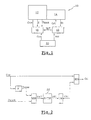
- FIG. 1 a motor vehicle powertrain 10 which comprises a motor 12 controlled according to a process in accordance with teachings of the invention.
- the motor 12 is coupled to a gearbox 14 to automated gear changes.
- the gearbox 14 can be either a box classic automatic or robotic gearbox.
- the motor 12 is controlled by an electronic unit of piloting 16 and the gearbox 14 is controlled by a electronic control unit 18.
- the engine 12 is for example of the internal combustion type gasoline and it advantageously includes an intake flap gas, or throttle body, motorized type, a device injection, and a fuel mixture ignition device which are electronically controlled by the control unit 16.
- the control unit 16 controls the load admitted into the cylinders of the engine 12 as a function of an engine torque setpoint C cm , and the engine then delivers a determined engine torque C m to the wheels of the vehicle.
- the driver of the vehicle acts on a device for controlling the acceleration of the vehicle, for example an accelerator pedal 20, which transmits to the control unit 16 information representative of the request for engine torque C m , or setpoint of conductive torque C cc .
- the engine torque setpoint C cm is equivalent to the driver torque setpoint C cc .
- the electronic control unit 18 of the gearbox 14 includes a control algorithm which determines a transmission ratio setpoint C rt , for example according to laws for changing the transmission ratio R t as a function of values mapped of the speed of the vehicle with respect to a depressing value of the accelerator pedal 20, which represents the acceleration Acc requested by the driver.
- control unit 16 implements a transition strategy ST when it detects a request to change from an initial transmission ratio R ti to a new transmission ratio R tn lower than the ratio initial R ti , the engine torque C m being substantially constant or increasing. This request will be called “downshift” RET in the rest of the description.
- the control unit 16 is for example informed of the RET downshift by the control unit 18.
- the transition strategy ST consists in determining, at regular time intervals ⁇ , from the setpoint of the driver torque C cc and from the maximum power P max available at the current rotation speed N of the engine 12, a limited torque setpoint C cl as a function of which the control unit 16 controls the load of the engine 12, so that the increase in the power transmitted to the wheels of the vehicle, or increase in the engine torque C m , is progressive between the initial transmission ratio R ti and the new transmission ratio R tn .
- the engine torque setpoint C cm is then equivalent to the limited torque setpoint C cl .
- FIG. 2 illustrates the operating principle of the transition strategy ST according to the invention at a given instant t, with a view to determining the limited torque setpoint C cl .
- the transition strategy ST begins by converting the driver torque setpoint C cc to the power setpoint P cons requested from the motor 12. For this, it suffices to carry out the product of the driver torque setpoint C cc by the current rotation speed N of the motor 12, that is to say the rotation speed N of the motor 12 at the instant t.
- the transition strategy ST determines an effective power P eff by choosing the lowest value between the power setpoint P cons and the maximum power P max available at the current rotation speed N of the motor 12.
- the effective power P eff corresponds to the power P m which would be effectively requested from the engine 12 if the transition strategy ST were not applied, the power P m requested from the engine 12 not being able to exceed the maximum power P max available.
- the transition strategy ST determines a filtered power P fil by applying to the effective power P eff a filtering algorithm, or filter 22, which produces a gradual increase in the filtered power P fil over time.
- the filter 22 must make it possible to obtain a profile for increasing the filtered power P fil which is more acceptable, that is to say more progressive, than the normal profile for increasing the effective power P eff in the absence of transition strategy ST.
- the letter "k” represents a constant which is fixed by design and the term P fil (t- ⁇ ) represents the filtered power P fil which was calculated at time t- ⁇ , ie to the previous iteration.
- the transition strategy ST converts the filtered power P wire into the filtered torque C wire . To do this, simply carry out the ratio of the filtered power P wire to the current rotation speed N of the motor 12.
- transition strategy ST determines the limited torque setpoint C cl by choosing the lowest value between the conductive torque setpoint C cc and the filtered torque C wire .
- the ST transition strategy is kept active throughout the RET downshift period, i.e. until the control unit 16 detects the end of the downshift RET, and until the torque setpoint Ccc conductor is less than or equal to the torque setpoint limited Ccl.
- the end of the downshift RET is detected here when the control unit 18 indicates to the control unit 16 that the new transmission ratio R tn is engaged.
- the conductive torque setpoint C cc can become less than or equal to the limited torque setpoint C cl under the effect of the filter 22 or due to a drop in the conductive torque setpoint C cc , for example when the driver wants to decrease vehicle acceleration.
- the torque setpoints in particular the driver torque setpoint C cc and the limited torque setpoint C cl , are replaced by associated power setpoints which are obtained respectively by performing the product of each torque setpoint given by the speed associated rotation N of the motor (12).
- control unit 16 can control the motor 12 as a function of a driver power setpoint at time t which is equal to the product of the driver torque setpoint C cc at time t by the rotation speed. N of motor 12 at time t.
- a power setpoint limited at time t can be calculated by performing the product of the limited torque setpoint C cl at time t by the rotation speed N of motor 12 at time t.
Landscapes
- Engineering & Computer Science (AREA)
- Chemical & Material Sciences (AREA)
- Combustion & Propulsion (AREA)
- Mechanical Engineering (AREA)
- Transportation (AREA)
- General Engineering & Computer Science (AREA)
- Automation & Control Theory (AREA)
- Control Of Transmission Device (AREA)
Abstract
Description
- la stratégie de transition consiste à effectuer, à
intervalles de temps réguliers, les opérations suivantes :
- déterminer une puissance effective en choisissant la valeur la plus faible entre, d'une part, une consigne de puissance, qui est égale au produit de la consigne de couple conducteur par le régime de rotation courant du moteur et, d'autre part, la puissance maximale disponible au régime de rotation courant du moteur ;
- calculer une puissance filtrée en appliquant à la puissance effective un algorithme de filtrage qui produit une augmentation progressive de la puissance filtrée ;
- déterminer la consigne de couple limité en choisissant la valeur la plus faible entre la consigne de couple conducteur et le couple filtré, qui est égal à la puissance filtrée rapportée sur le régime de rotation courant du moteur ;
- l'unité de pilotage désactive la stratégie de transition
lorsque les deux conditions suivantes sont remplies
simultanément :
- l'unité de pilotage a détecté la fin du passage du rapport initial de transmission au nouveau rapport de transmission ;
- et la consigne de couple conducteur est inférieure ou égale au couple filtré ;
- on substitue aux consignes de couple des consignes de puissance associées qui sont obtenues respectivement en effectuant le produit de chaque consigne de couple par le régime de rotation associé du moteur.
- la figure 1 est un diagramme schématique qui représente un groupe motopropulseur commandé par un procédé conforme aux enseignements de l'invention ;
- la figure 2 est un diagramme schématique qui illustre le fonctionnement de la stratégie de transition du procédé de commande selon l'invention.
Claims (4)
- Procédé de commande d'un groupe motopropulseur (10) de véhicule automobile comportant un moteur (12), qui est commandé par une unité électronique de pilotage (16), et une boíte de vitesses (14) à changements de rapports (Rt) automatisés, qui est commandée par une unité électronique de commande (18), du type dans lequel l'unité de pilotage (16) reçoit, de la part du conducteur et par l'intermédiaire d'un dispositif de commande (20) de l'accélération, une information représentative de la demande de couple moteur (Cm), ou consigne de couple conducteur (Ccc), en fonction de laquelle l'unité de pilotage (16) est susceptible de piloter la charge du moteur (12), et du type dans lequel l'unité de pilotage (16), lorsqu'elle détecte une demande de passage d'un rapport initial de transmission (Rti) à un nouveau rapport de transmission (Rtn) inférieur au rapport initial (Rti), le couple moteur (Cm) étant sensiblement constant ou en hausse, met en oeuvre une stratégie de transition (ST) au cours de laquelle elle diminue le couple moteur (Cm),
caractérisé en ce que la stratégie de transition (ST) consiste à déterminer, à intervalles de temps (τ) réguliers, à partir de la consigne de couple conducteur (Ccc) et à partir de la puissance maximale (Pmax) disponible au régime de rotation courant (N) du moteur (12), une consigne de couple limité (Ccl) en fonction de laquelle l'unité de pilotage (16) commande la charge du moteur (12), de manière que l'augmentation de la puissance transmise aux roues du véhicule soit progressive entre le rapport initial de transmission (Rti) et le nouveau rapport de transmission (Rtn). - Procédé de commande selon la revendication précédente, caractérisé en ce que la stratégie de transition (ST) consiste à effectuer, à intervalles de temps (τ) réguliers, les opérations suivantes :déterminer une puissance effective (Peff) en choisissant la valeur la plus faible entre, d'une part, une consigne de puissance (Pcons), qui est égale au produit de la consigne de couple conducteur (Ccc) par le régime de rotation courant (N) du moteur (12) et, d'autre part, la puissance maximale (Pmax) disponible au régime de rotation courant (N) du moteur (12) ;calculer une puissance filtrée (Pfil) en appliquant à la puissance effective (Peff) un algorithme de filtrage qui produit une augmentation progressive de la puissance filtrée (Pfil) ;déterminer la consigne de couple limité (Ccl) en choisissant la valeur la plus faible entre la consigne de couple conducteur (Ccc) et le couple filtré (Cfil), qui est égal à la puissance filtrée (Pfil) rapportée sur le régime de rotation courant (N) du moteur (12).
- Procédé de commande selon la revendication précédente, caractérisé en ce que l'unité de pilotage (16) désactive la stratégie de transition (ST) lorsque les deux conditions suivantes sont remplies simultanément :l'unité de pilotage (16) a détecté la fin du passage du rapport initial de transmission (Rti) au nouveau rapport de transmission (Rtn) ;et la consigne de couple conducteur (Ccc) est inférieure ou égale au couple filtré (Cfil).
- Procédé de commande selon l'une quelconque des revendications précédentes, caractérisé en ce que l'on substitue aux consignes de couple (Ccm, Ccc, Ccl) des consignes de puissance associées qui sont obtenues respectivement en effectuant le produit de chaque consigne de couple (Ccm, Ccc, Ccl) par le régime de rotation (N) associé du moteur (12).
Applications Claiming Priority (2)
| Application Number | Priority Date | Filing Date | Title |
|---|---|---|---|
| FR0100512A FR2819455B1 (fr) | 2001-01-16 | 2001-01-16 | Procede de commande d'un groupe motopropulseur pendant les changements de rapports de sa transmission automatique |
| FR0100512 | 2001-01-16 |
Publications (2)
| Publication Number | Publication Date |
|---|---|
| EP1223070A1 true EP1223070A1 (fr) | 2002-07-17 |
| EP1223070B1 EP1223070B1 (fr) | 2010-05-19 |
Family
ID=8858851
Family Applications (1)
| Application Number | Title | Priority Date | Filing Date |
|---|---|---|---|
| EP02290068A Expired - Lifetime EP1223070B1 (fr) | 2001-01-16 | 2002-01-11 | Procédé de commande d'un groupe motopropulseur pendant les changements de rapports de sa transmission automatique |
Country Status (3)
| Country | Link |
|---|---|
| EP (1) | EP1223070B1 (fr) |
| DE (1) | DE60236388D1 (fr) |
| FR (1) | FR2819455B1 (fr) |
Cited By (1)
| Publication number | Priority date | Publication date | Assignee | Title |
|---|---|---|---|---|
| EP1447259A2 (fr) | 2003-02-14 | 2004-08-18 | Toyota Jidosha Kabushiki Kaisha | Dispositif et procédé de commande de la puissance de moteurs à combustion interne |
Citations (4)
| Publication number | Priority date | Publication date | Assignee | Title |
|---|---|---|---|---|
| EP0885767A2 (fr) * | 1997-06-20 | 1998-12-23 | Bayerische Motoren Werke Aktiengesellschaft, Patentabteilung AJ-3 | Système pour la régulation du couple moteur selon le ouple d'entrée requis apr la transmission |
| DE19845157A1 (de) | 1998-10-01 | 2000-04-06 | Zahnradfabrik Friedrichshafen | Verfahren zur Steuerung des Drehmomentes einer Brennkraftmaschine eines Kraftfahrzeuges mit einem Automatgetriebe |
| US6064934A (en) * | 1996-03-26 | 2000-05-16 | Robert Bosch Gmbh | Process and device for regulating the torque derived from a drive unit |
| DE19950664A1 (de) * | 1999-10-21 | 2001-04-26 | Zahnradfabrik Friedrichshafen | Verfahren zur Steuerung eines Automatgetriebes, insbesondere Stufenautomatgetriebes, für ein Kraftfahrzeug |
-
2001
- 2001-01-16 FR FR0100512A patent/FR2819455B1/fr not_active Expired - Fee Related
-
2002
- 2002-01-11 EP EP02290068A patent/EP1223070B1/fr not_active Expired - Lifetime
- 2002-01-11 DE DE60236388T patent/DE60236388D1/de not_active Expired - Lifetime
Patent Citations (4)
| Publication number | Priority date | Publication date | Assignee | Title |
|---|---|---|---|---|
| US6064934A (en) * | 1996-03-26 | 2000-05-16 | Robert Bosch Gmbh | Process and device for regulating the torque derived from a drive unit |
| EP0885767A2 (fr) * | 1997-06-20 | 1998-12-23 | Bayerische Motoren Werke Aktiengesellschaft, Patentabteilung AJ-3 | Système pour la régulation du couple moteur selon le ouple d'entrée requis apr la transmission |
| DE19845157A1 (de) | 1998-10-01 | 2000-04-06 | Zahnradfabrik Friedrichshafen | Verfahren zur Steuerung des Drehmomentes einer Brennkraftmaschine eines Kraftfahrzeuges mit einem Automatgetriebe |
| DE19950664A1 (de) * | 1999-10-21 | 2001-04-26 | Zahnradfabrik Friedrichshafen | Verfahren zur Steuerung eines Automatgetriebes, insbesondere Stufenautomatgetriebes, für ein Kraftfahrzeug |
Cited By (2)
| Publication number | Priority date | Publication date | Assignee | Title |
|---|---|---|---|---|
| EP1447259A2 (fr) | 2003-02-14 | 2004-08-18 | Toyota Jidosha Kabushiki Kaisha | Dispositif et procédé de commande de la puissance de moteurs à combustion interne |
| EP1447259A3 (fr) * | 2003-02-14 | 2008-08-13 | Toyota Jidosha Kabushiki Kaisha | Dispositif et procédé de commande de la puissance de moteurs à combustion interne |
Also Published As
| Publication number | Publication date |
|---|---|
| FR2819455B1 (fr) | 2003-04-11 |
| FR2819455A1 (fr) | 2002-07-19 |
| DE60236388D1 (de) | 2010-07-01 |
| EP1223070B1 (fr) | 2010-05-19 |
Similar Documents
| Publication | Publication Date | Title |
|---|---|---|
| CN102211578B (zh) | 汽车运行方法 | |
| EP1128977B1 (fr) | Procede de commande du couple moteur pendant les changements de vitesse | |
| FR2851629A1 (fr) | Procede et dispositf de gestion de l'unite motrice d'un vehicule | |
| JP2010241329A (ja) | 車両の動力伝達制御装置 | |
| FR3058697B1 (fr) | Dispositif de pilotage d'une boite de vitesses robotisee pour vehicule automobile a propulsion hybride | |
| EP3074257B1 (fr) | Procede et systeme de demarrage d'un moteur thermique | |
| FR3106107A1 (fr) | Procede pour optimiser un regime de moteur thermique d’un vehicule a boite de vitesse automotisee notamment lors d’un accostage. | |
| EP3292032B1 (fr) | Procede de gestion des pentes de l'agrement preventif en deceleration | |
| JP2010241325A (ja) | 車両の動力伝達制御装置 | |
| EP3237257B1 (fr) | Procédé de passage automatique d'un véhicule automobile en mode roue libre | |
| EP1223070B1 (fr) | Procédé de commande d'un groupe motopropulseur pendant les changements de rapports de sa transmission automatique | |
| JP2009167873A (ja) | 動力源の制御装置 | |
| EP1310401B1 (fr) | Procédé de changement de rapport descendant sur une transmission automatisée | |
| EP1791715B1 (fr) | Procede de commande a plusieurs modes de fonctionnement d'une transmission automatisee pour un vehicule automobile, notamment pour un avancement au ralenti du vehicule automobile avec frein active et dispositif correspondant | |
| EP1547849A1 (fr) | Dispositif de commande d'une boíte de vitesses automatisée destiné à améliorer la qualité des passages montants des vitesses sous faible couple du moteur | |
| FR2818936A1 (fr) | Procede de mise en oeuvre d'une transmission d'un vehicule automobile et installation pour la realisation du procede | |
| EP1068088A1 (fr) | Procede d'assistance pour une faible vitesse du moteur thermique d'un vehicule hybride | |
| EP1995449A2 (fr) | Procédé de commande de l'arrêt et du redémarrage automatique du moteur d'un véhicule en fonction de la pente | |
| FR2646128A1 (fr) | Dispositif pour l'actionnement automatique d'un embrayage | |
| WO2025119625A1 (fr) | Procédé et dispositif de gestion du fonctionnement d'un moteur thermique d'un véhicule automobile hybride équipé d'une boite de vitesses à crabots | |
| EP1293376B1 (fr) | Stratégie de réembrayage anticipée pendant les changements de rapport montant des transmissions automatisées | |
| EP1846647A1 (fr) | Procede de controle de l'inversion de la puissance dans un systeme comportant un convertisseur de couple et ensemble mecanique integrant ledit procede | |
| WO2004072458A1 (fr) | Procede et dispositif de commande du groupe moto-propulseur d’un vehicule automobile anime par un moteur a combustion interne | |
| FR3001937A1 (fr) | Procede de controle des changements de mode de fonctionnement d'un vehicule, passant directement du premier au troisieme mode | |
| EP2529129B1 (fr) | Procede de commande d'un moteur et d'un embrayage pilote pendant une premiere phase de commande d'un changement de rapport de transmission d'une boite de vitesses mecanique |
Legal Events
| Date | Code | Title | Description |
|---|---|---|---|
| PUAI | Public reference made under article 153(3) epc to a published international application that has entered the european phase |
Free format text: ORIGINAL CODE: 0009012 |
|
| AK | Designated contracting states |
Kind code of ref document: A1 Designated state(s): AT BE CH CY DE DK ES FI FR GB GR IE IT LI LU MC NL PT SE TR |
|
| AX | Request for extension of the european patent |
Free format text: AL;LT;LV;MK;RO;SI |
|
| RAP1 | Party data changed (applicant data changed or rights of an application transferred) |
Owner name: RENAULT S.A.S. |
|
| AKX | Designation fees paid | ||
| 17P | Request for examination filed |
Effective date: 20030103 |
|
| RBV | Designated contracting states (corrected) |
Designated state(s): BE DE ES |
|
| REG | Reference to a national code |
Ref country code: DE Ref legal event code: 8566 |
|
| 17Q | First examination report despatched |
Effective date: 20070817 |
|
| GRAP | Despatch of communication of intention to grant a patent |
Free format text: ORIGINAL CODE: EPIDOSNIGR1 |
|
| RIC1 | Information provided on ipc code assigned before grant |
Ipc: B60W 30/18 20060101ALI20090930BHEP Ipc: B60W 10/06 20060101ALN20090930BHEP Ipc: F16H 63/50 20060101AFI20090930BHEP Ipc: F16H 61/04 20060101ALN20090930BHEP Ipc: B60W 10/10 20060101ALN20090930BHEP Ipc: F16H 59/20 20060101ALN20090930BHEP |
|
| GRAS | Grant fee paid |
Free format text: ORIGINAL CODE: EPIDOSNIGR3 |
|
| GRAA | (expected) grant |
Free format text: ORIGINAL CODE: 0009210 |
|
| AK | Designated contracting states |
Kind code of ref document: B1 Designated state(s): BE DE ES |
|
| REF | Corresponds to: |
Ref document number: 60236388 Country of ref document: DE Date of ref document: 20100701 Kind code of ref document: P |
|
| PG25 | Lapsed in a contracting state [announced via postgrant information from national office to epo] |
Ref country code: ES Free format text: LAPSE BECAUSE OF FAILURE TO SUBMIT A TRANSLATION OF THE DESCRIPTION OR TO PAY THE FEE WITHIN THE PRESCRIBED TIME-LIMIT Effective date: 20100830 |
|
| PLBE | No opposition filed within time limit |
Free format text: ORIGINAL CODE: 0009261 |
|
| STAA | Information on the status of an ep patent application or granted ep patent |
Free format text: STATUS: NO OPPOSITION FILED WITHIN TIME LIMIT |
|
| 26N | No opposition filed |
Effective date: 20110222 |
|
| REG | Reference to a national code |
Ref country code: DE Ref legal event code: R097 Ref document number: 60236388 Country of ref document: DE Effective date: 20110221 |
|
| PGFP | Annual fee paid to national office [announced via postgrant information from national office to epo] |
Ref country code: BE Payment date: 20160120 Year of fee payment: 15 |
|
| PGFP | Annual fee paid to national office [announced via postgrant information from national office to epo] |
Ref country code: DE Payment date: 20170120 Year of fee payment: 16 |
|
| PG25 | Lapsed in a contracting state [announced via postgrant information from national office to epo] |
Ref country code: BE Free format text: LAPSE BECAUSE OF NON-PAYMENT OF DUE FEES Effective date: 20170131 |
|
| REG | Reference to a national code |
Ref country code: BE Ref legal event code: MM Effective date: 20170131 |
|
| REG | Reference to a national code |
Ref country code: DE Ref legal event code: R119 Ref document number: 60236388 Country of ref document: DE |
|
| PG25 | Lapsed in a contracting state [announced via postgrant information from national office to epo] |
Ref country code: DE Free format text: LAPSE BECAUSE OF NON-PAYMENT OF DUE FEES Effective date: 20180801 |