EP1222987A1 - Induction heating tool - Google Patents
Induction heating tool Download PDFInfo
- Publication number
- EP1222987A1 EP1222987A1 EP02250250A EP02250250A EP1222987A1 EP 1222987 A1 EP1222987 A1 EP 1222987A1 EP 02250250 A EP02250250 A EP 02250250A EP 02250250 A EP02250250 A EP 02250250A EP 1222987 A1 EP1222987 A1 EP 1222987A1
- Authority
- EP
- European Patent Office
- Prior art keywords
- semi
- another
- circular
- induction coil
- components
- Prior art date
- Legal status (The legal status is an assumption and is not a legal conclusion. Google has not performed a legal analysis and makes no representation as to the accuracy of the status listed.)
- Withdrawn
Links
Images

Classifications
-
- B—PERFORMING OPERATIONS; TRANSPORTING
- B23—MACHINE TOOLS; METAL-WORKING NOT OTHERWISE PROVIDED FOR
- B23K—SOLDERING OR UNSOLDERING; WELDING; CLADDING OR PLATING BY SOLDERING OR WELDING; CUTTING BY APPLYING HEAT LOCALLY, e.g. FLAME CUTTING; WORKING BY LASER BEAM
- B23K3/00—Tools, devices, or special appurtenances for soldering, e.g. brazing, or unsoldering, not specially adapted for particular methods
- B23K3/04—Heating appliances
- B23K3/047—Heating appliances electric
-
- B—PERFORMING OPERATIONS; TRANSPORTING
- B01—PHYSICAL OR CHEMICAL PROCESSES OR APPARATUS IN GENERAL
- B01J—CHEMICAL OR PHYSICAL PROCESSES, e.g. CATALYSIS OR COLLOID CHEMISTRY; THEIR RELEVANT APPARATUS
- B01J29/00—Catalysts comprising molecular sieves
- B01J29/82—Phosphates
- B01J29/84—Aluminophosphates containing other elements, e.g. metals, boron
- B01J29/85—Silicoaluminophosphates (SAPO compounds)
-
- B—PERFORMING OPERATIONS; TRANSPORTING
- B01—PHYSICAL OR CHEMICAL PROCESSES OR APPARATUS IN GENERAL
- B01J—CHEMICAL OR PHYSICAL PROCESSES, e.g. CATALYSIS OR COLLOID CHEMISTRY; THEIR RELEVANT APPARATUS
- B01J37/00—Processes, in general, for preparing catalysts; Processes, in general, for activation of catalysts
- B01J37/08—Heat treatment
-
- B—PERFORMING OPERATIONS; TRANSPORTING
- B23—MACHINE TOOLS; METAL-WORKING NOT OTHERWISE PROVIDED FOR
- B23K—SOLDERING OR UNSOLDERING; WELDING; CLADDING OR PLATING BY SOLDERING OR WELDING; CUTTING BY APPLYING HEAT LOCALLY, e.g. FLAME CUTTING; WORKING BY LASER BEAM
- B23K1/00—Soldering, e.g. brazing, or unsoldering
- B23K1/002—Soldering by means of induction heating
-
- C—CHEMISTRY; METALLURGY
- C07—ORGANIC CHEMISTRY
- C07C—ACYCLIC OR CARBOCYCLIC COMPOUNDS
- C07C1/00—Preparation of hydrocarbons from one or more compounds, none of them being a hydrocarbon
- C07C1/20—Preparation of hydrocarbons from one or more compounds, none of them being a hydrocarbon starting from organic compounds containing only oxygen atoms as heteroatoms
-
- B—PERFORMING OPERATIONS; TRANSPORTING
- B01—PHYSICAL OR CHEMICAL PROCESSES OR APPARATUS IN GENERAL
- B01J—CHEMICAL OR PHYSICAL PROCESSES, e.g. CATALYSIS OR COLLOID CHEMISTRY; THEIR RELEVANT APPARATUS
- B01J2229/00—Aspects of molecular sieve catalysts not covered by B01J29/00
- B01J2229/10—After treatment, characterised by the effect to be obtained
- B01J2229/24—After treatment, characterised by the effect to be obtained to stabilize the molecular sieve structure
-
- B—PERFORMING OPERATIONS; TRANSPORTING
- B01—PHYSICAL OR CHEMICAL PROCESSES OR APPARATUS IN GENERAL
- B01J—CHEMICAL OR PHYSICAL PROCESSES, e.g. CATALYSIS OR COLLOID CHEMISTRY; THEIR RELEVANT APPARATUS
- B01J2229/00—Aspects of molecular sieve catalysts not covered by B01J29/00
- B01J2229/30—After treatment, characterised by the means used
- B01J2229/40—Special temperature treatment, i.e. other than just for template removal
-
- B—PERFORMING OPERATIONS; TRANSPORTING
- B23—MACHINE TOOLS; METAL-WORKING NOT OTHERWISE PROVIDED FOR
- B23K—SOLDERING OR UNSOLDERING; WELDING; CLADDING OR PLATING BY SOLDERING OR WELDING; CUTTING BY APPLYING HEAT LOCALLY, e.g. FLAME CUTTING; WORKING BY LASER BEAM
- B23K2101/00—Articles made by soldering, welding or cutting
- B23K2101/04—Tubular or hollow articles
- B23K2101/06—Tubes
-
- C—CHEMISTRY; METALLURGY
- C07—ORGANIC CHEMISTRY
- C07C—ACYCLIC OR CARBOCYCLIC COMPOUNDS
- C07C2529/00—Catalysts comprising molecular sieves
- C07C2529/82—Phosphates
- C07C2529/84—Aluminophosphates containing other elements, e.g. metals, boron
- C07C2529/85—Silicoaluminophosphates (SAPO compounds)
-
- Y—GENERAL TAGGING OF NEW TECHNOLOGICAL DEVELOPMENTS; GENERAL TAGGING OF CROSS-SECTIONAL TECHNOLOGIES SPANNING OVER SEVERAL SECTIONS OF THE IPC; TECHNICAL SUBJECTS COVERED BY FORMER USPC CROSS-REFERENCE ART COLLECTIONS [XRACs] AND DIGESTS
- Y02—TECHNOLOGIES OR APPLICATIONS FOR MITIGATION OR ADAPTATION AGAINST CLIMATE CHANGE
- Y02P—CLIMATE CHANGE MITIGATION TECHNOLOGIES IN THE PRODUCTION OR PROCESSING OF GOODS
- Y02P30/00—Technologies relating to oil refining and petrochemical industry
- Y02P30/20—Technologies relating to oil refining and petrochemical industry using bio-feedstock
-
- Y—GENERAL TAGGING OF NEW TECHNOLOGICAL DEVELOPMENTS; GENERAL TAGGING OF CROSS-SECTIONAL TECHNOLOGIES SPANNING OVER SEVERAL SECTIONS OF THE IPC; TECHNICAL SUBJECTS COVERED BY FORMER USPC CROSS-REFERENCE ART COLLECTIONS [XRACs] AND DIGESTS
- Y10—TECHNICAL SUBJECTS COVERED BY FORMER USPC
- Y10S—TECHNICAL SUBJECTS COVERED BY FORMER USPC CROSS-REFERENCE ART COLLECTIONS [XRACs] AND DIGESTS
- Y10S502/00—Catalyst, solid sorbent, or support therefor: product or process of making
- Y10S502/514—Process applicable either to preparing or to regenerating or to rehabilitating catalyst or sorbent
-
- Y—GENERAL TAGGING OF NEW TECHNOLOGICAL DEVELOPMENTS; GENERAL TAGGING OF CROSS-SECTIONAL TECHNOLOGIES SPANNING OVER SEVERAL SECTIONS OF THE IPC; TECHNICAL SUBJECTS COVERED BY FORMER USPC CROSS-REFERENCE ART COLLECTIONS [XRACs] AND DIGESTS
- Y10—TECHNICAL SUBJECTS COVERED BY FORMER USPC
- Y10S—TECHNICAL SUBJECTS COVERED BY FORMER USPC CROSS-REFERENCE ART COLLECTIONS [XRACs] AND DIGESTS
- Y10S585/00—Chemistry of hydrocarbon compounds
- Y10S585/8995—Catalyst and recycle considerations
- Y10S585/906—Catalyst preservation or manufacture, e.g. activation before use
Definitions
- the present invention relates generally to a tool for induction heating of components to be joined one to the other and particularly relates to an induction heating coil for brazing copper components at electrical generator locations difficult to access and braze by conventional brazing tools.
- brazing component parts together is an old and tried method of joining the parts.
- brazing is accomplished by using an open flame, for example, propane, and an oxygen gas in conjunction with brazing filler and flux materials. While such brazing method and tools are satisfactory for original equipment manufacture, oftentimes there is a need for brazing parts to one another in cramped and confined spaces where the use of an open flame cannot safely be utilized.
- liquid cooled high voltage bushing components are located in the electrical generator lower frame extension. Field brazing of these components is oftentimes unacceptable in the power generating facility. Accordingly, there is a need for a brazing tool for induction heating of the parts to be brazed to one another which can be used in cramped, confined spaces, reused for multiple applications, and used for original equipment as well as field repair applications.
- a tool for brazing application including an induction coil formed of a pair of induction coil components which are substantially similar to one another, i.e., substantially mirror images of one another.
- Each component includes a linear extension or leg, whose proximal end is coupled to a first end of a generally semi-circular induction coil portion.
- the opposite or second end of the semi-circular induction coil portion terminates in a flange such that the opposed induction coil components can be secured one to the other.
- the distal end of each extension has an adapter flange portion forming part of an adapter for securing the tool to an induction brazer for supplying electrical current and cooling water to the induction tool.
- an induction coil extending a full 360° is formed having a specific diameter designed for a close fit about and used to join components of a particular diameter.
- the linear extensions lie parallel to one another along their lengths and have electrical insulating material therebetween.
- the induction coil components are preferably formed of hollow, electrical conductive, e.g., copper.
- the tubes are rectilinear in cross-section.
- a pair of nipples one on each coil portion end.
- a flexible conduit e.g., a hose
- an electrically conductive material for example, a braid, interconnects the nipples or opposite sides of the semi-circular coil portions to one another to ensure electrical conductivity between the two component halves.
- the semi-circular component portions can be disposed on opposite sides of the parts to be brazed to one another and bolted to one another about the parts and to the brazer.
- the diameter of the semi-circular portions closely approximates the diameter of the parts to be brazed whereby high coupling efficiency with minimum applied power is provided while reaching and holding the brazing temperature.
- the temperature is raised to the brazing temperature and the filler material, e.g., about 80% copper, 15% silver and 5% phosphorus, is applied to the parts.
- the filler material e.g., about 80% copper, 15% silver and 5% phosphorus
- Other brazing alloys may be used.
- a cooling medium e.g., water, is simultaneously supplied from the brazer through the tool to cool the tool during brazing.
- the components are separated from one another by detaching the bolted connections at the semi-circular component portion end, as well as at the adapter end.
- the brazing tool is then opened, e.g., in a clamshell manner, and removed from about the brazed parts for reuse and reapplication to other parts required to be brazed to one another. It will be appreciated that the brazing tool is thus compact and can be utilized in confined spaces, for example, to braze the generator high voltage bushings and component parts thereof as necessary in a generator. Applications of the tool hereof to braze other parts in other environments are also within the scope hereof.
- an induction coil for brazing comprising a pair of induction coil components, each component including a generally semi-circular induction coil portion and a generally linear extension extending from a first end of the semi-circular induction coil portion, each coil portion and extension being formed of a hollow, electrical conductive material for flowing a cooling medium and conducting electricity between an end of the extension, along the extension, and through the semi-circular induction coil portion to a second end of the semi-circular induction coil portion opposite the first end, means for releasably securing the components to one another such that the semi-circular induction coil portions form a generally circular coil for surrounding workpieces to be brazed to one another and with the extensions in opposed registration with one another and a bypass conduit for hydraulically connecting the coil portions to one another adjacent the second end thereof.
- an induction coil for brazing comprising a pair of induction coil components, each component including a generally semi-circular induction coil portion and an extension extending from a first end of the semi-circular induction coil portion, each coil portion and extension being formed of a hollow, electrical conductive material for flowing a cooling medium and conducting electricity between an end of the extension, along the extension, and through the semi-circular induction coil portion to a second end of the semi-circular induction coil portion opposite the first end, the second ends of the semi-circular induction coil portions being closed, a releasable securing device for securing the components to one another adjacent the second ends thereof such that the semi-circular induction coil portions form a generally circular coil for surrounding workpieces to be brazed to one another and a bypass conduit for hydraulically connecting the coil portions to one another adjacent the second end thereof whereby the cooling medium may flow serially through one component and subsequently another component.
- Tool 10 includes a pair of tool components, i.e., tool halves, 12 and 14 which comprise substantially mirror images of one another.
- Each component 12 and 14 includes a generally semi-circular induction coil portion 16 and a generally linear extension or leg 18 extending from a first end 20 of the semi-circular induction coil portion 16.
- the portion 16 and extension 18 are preferably formed of a hollow, electrically conductive material.
- portion 16 and extension 18 may each be formed of copper tubing having a rectilinear cross-section, with the tubing of portion 16 and extension 18 being connected to and in communication with one another.
- Each extension 18 terminates at its distal end in a flange portion 22 and an opening 24.
- the flanges 22 form an adapter at the end of the tool having bolt openings for securing the tool to an induction brazer, not shown, for supplying power to the tool.
- the tool 10 is also secured to the brazer such that a cooling medium, e.g., water, may be supplied to the tool through an opening 24 for flow along one extension 18 and coil portion of one component 16 and returned through the coil portion 16, extension 18 and opening 24 of the other component.
- a cooling medium e.g., water
- each coil portion 16 of the end 28 preferably terminates in a flange 30 having bolt holes.
- the components 12 and 14 thus having mating flanges 30 which may be bolted one to the other. It will be appreciated that other devices for securing the components 12 and 14 may be used such as releasable clamps.
- each coil portion 16 also includes a connection, i.e., a nipple 32 in communication with the water flow passage within the coil portion 16.
- a bypass conduit preferably flexible tubing 34, for example, a rubber hose section, is releasably secured at opposite ends to the nipples 32, spanning the joint between the second ends 28 of the coil portions 16.
- Hose clamps 36 are provided for releasably securing the tubing 34 to the nipples 32.
- a braid 38 of electrically conductive material is releasably interconnected between the nipples 32 to ensure electrical connection between the coil portions 16 when the induction tool components 12 and 14 are secured one to the other with the coil portions 16 about the parts to be joined to one another. While the flanges 30 of the two components are bolted to and in electrical contact with one another, that contact may deteriorate through usage. Hence, the braid 38 ensures electrical contact.
- the aforedescribed tool is compact and is thus usable and reusable in confined spaces for joining various parts to one another.
- the high voltage bushings within a generator lower frame extension of an electrical generator may be induction-heated by this tool, notwithstanding the cramped and confined space of the housing for the bushings.
- the diameters of the induction coil portions 16 are dimensioned for a close-fitting relation with the parts to be brazed to one another, thereby affording a high coupling efficiency with minimum power enabling the tool to quickly reach and hold brazing temperatures.
- the components 12 and 14 are separated one from the other at opposite ends, preferably leaving the braid 38 and tubing connected to those ends.
- the tool may thus be deployed in a generally clamshell configuration about the parts to be brazed such that the coil portions 16 can be disposed about the opposite sides of such parts.
- the portions 16 are joined to one another, for example, by bolting the flanges 30 to one another.
- the adapter at the distal end of the extensions 18 is bolted to the induction brazer.
- cooling water is supplied from the brazer through the hollow tubular material of the extension 18 and coil portion 16 of one component in series via the nipples 32 and tubing 14 through the extension and coil portion of the other component.
- Electrical current is also provided from the induction brazer.
- Filler material is also supplied to the parts to be brazed to one another, e.g., using a rod of such filler material, and the coil portions are brought to the brazing temperature, for example, 1200°F. When the brazing temperature is reached and maintained sufficiently to melt the filler and complete the brazed joint, the power and water flow are cut off.
- the tool 10 is then removed by unbolting the tool from the brazer and separating the components 12 and 14 from one another by unbolting the flanges 30. The resulting clamshell-type configuration is then removed from about the brazed parts.
- the present tool may be used and reused in a safe manner, for example, in a power generating facility where cramped and confined quarters preclude the use of other types of tools for brazing. Also, by forming the coil portions in close-fitting relation about the parts to be joined, high coupling heating efficiency with minimum power input is provided.
- the tool for example, can be repeatedly used to connect parts within the cramped spaces without the use of an open flame or oxygen gas and, hence, can be used safely and efficiently.
Abstract
An induction brazing tool (10) includes a pair of induction coil components
(12, 14) each having a linear extension (18) and a semi-circular coil (16) at
one end. A distal end of each component remote from the semi-circular coil
includes a flange (22) for connecting the tool to an induction brazer. The
components are formed of electrical conductive hollow copper tubing. The
opposite end of each component includes a flange (30) for bolting the
components to one another. Nipples (32) are provided the ends of the coil
portions and a flexible hose (34) interconnects the nipples. A braid (36) of
electrical conductive material also connects the nipples. In use, the
components are opened to form a clamshell configuration, disposed about
parts to be brazed and bolted together and to the brazer. By flowing electrical
current and cooling water along the tool, a brazed joint is effected.
Description
- The present invention relates generally to a tool for induction heating of components to be joined one to the other and particularly relates to an induction heating coil for brazing copper components at electrical generator locations difficult to access and braze by conventional brazing tools.
- Brazing component parts together is an old and tried method of joining the parts. Typically, brazing is accomplished by using an open flame, for example, propane, and an oxygen gas in conjunction with brazing filler and flux materials. While such brazing method and tools are satisfactory for original equipment manufacture, oftentimes there is a need for brazing parts to one another in cramped and confined spaces where the use of an open flame cannot safely be utilized. For example, in a power generating facility, liquid cooled high voltage bushing components are located in the electrical generator lower frame extension. Field brazing of these components is oftentimes unacceptable in the power generating facility. Accordingly, there is a need for a brazing tool for induction heating of the parts to be brazed to one another which can be used in cramped, confined spaces, reused for multiple applications, and used for original equipment as well as field repair applications.
- In accordance with a preferred embodiment of the present invention, there is provided a tool for brazing application including an induction coil formed of a pair of induction coil components which are substantially similar to one another, i.e., substantially mirror images of one another. Each component includes a linear extension or leg, whose proximal end is coupled to a first end of a generally semi-circular induction coil portion. The opposite or second end of the semi-circular induction coil portion terminates in a flange such that the opposed induction coil components can be secured one to the other. The distal end of each extension has an adapter flange portion forming part of an adapter for securing the tool to an induction brazer for supplying electrical current and cooling water to the induction tool. In that manner, an induction coil extending a full 360° is formed having a specific diameter designed for a close fit about and used to join components of a particular diameter. The linear extensions lie parallel to one another along their lengths and have electrical insulating material therebetween. The induction coil components are preferably formed of hollow, electrical conductive, e.g., copper. Preferably, the tubes are rectilinear in cross-section.
- At the opposite end of the tool and adjacent the juncture of the second ends of the semi-circular coil portions, there are provided a pair of nipples, one on each coil portion end. A flexible conduit, e.g., a hose, is attached to the nipples, whereby water flowing through the linear extension and semi-circular portion on one side of the tool traverses the joint between the components for flow through the semi-circular coil portion and linear extension of the other side of the tool. Additionally, an electrically conductive material, for example, a braid, interconnects the nipples or opposite sides of the semi-circular coil portions to one another to ensure electrical conductivity between the two component halves.
- With the foregoing arrangement of the tool, the semi-circular component portions can be disposed on opposite sides of the parts to be brazed to one another and bolted to one another about the parts and to the brazer. The diameter of the semi-circular portions closely approximates the diameter of the parts to be brazed whereby high coupling efficiency with minimum applied power is provided while reaching and holding the brazing temperature. With the semi-circular portions of the brazing tool about the parts, the temperature is raised to the brazing temperature and the filler material, e.g., about 80% copper, 15% silver and 5% phosphorus, is applied to the parts. Other brazing alloys may be used. A cooling medium, e.g., water, is simultaneously supplied from the brazer through the tool to cool the tool during brazing. After brazing, the components are separated from one another by detaching the bolted connections at the semi-circular component portion end, as well as at the adapter end. The brazing tool is then opened, e.g., in a clamshell manner, and removed from about the brazed parts for reuse and reapplication to other parts required to be brazed to one another. It will be appreciated that the brazing tool is thus compact and can be utilized in confined spaces, for example, to braze the generator high voltage bushings and component parts thereof as necessary in a generator. Applications of the tool hereof to braze other parts in other environments are also within the scope hereof.
- In a preferred embodiment according to the present invention, there is provided an induction coil for brazing comprising a pair of induction coil components, each component including a generally semi-circular induction coil portion and a generally linear extension extending from a first end of the semi-circular induction coil portion, each coil portion and extension being formed of a hollow, electrical conductive material for flowing a cooling medium and conducting electricity between an end of the extension, along the extension, and through the semi-circular induction coil portion to a second end of the semi-circular induction coil portion opposite the first end, means for releasably securing the components to one another such that the semi-circular induction coil portions form a generally circular coil for surrounding workpieces to be brazed to one another and with the extensions in opposed registration with one another and a bypass conduit for hydraulically connecting the coil portions to one another adjacent the second end thereof.
- In a further preferred embodiment according to the present invention, there is provided an induction coil for brazing comprising a pair of induction coil components, each component including a generally semi-circular induction coil portion and an extension extending from a first end of the semi-circular induction coil portion, each coil portion and extension being formed of a hollow, electrical conductive material for flowing a cooling medium and conducting electricity between an end of the extension, along the extension, and through the semi-circular induction coil portion to a second end of the semi-circular induction coil portion opposite the first end, the second ends of the semi-circular induction coil portions being closed, a releasable securing device for securing the components to one another adjacent the second ends thereof such that the semi-circular induction coil portions form a generally circular coil for surrounding workpieces to be brazed to one another and a bypass conduit for hydraulically connecting the coil portions to one another adjacent the second end thereof whereby the cooling medium may flow serially through one component and subsequently another component.
- An embodiment of the invention will now be described, by way of example, with reference to the accompanying drawings, in which:
- FIGURE 1 is a plan view of an induction brazing tool constructed in accordance with a preferred embodiment of the present invention and illustrated in a closed position about parts being brazed;
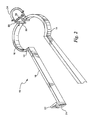
- FIGURE 2 is a perspective view of the brazing tool illustrated in Figure 1 in an open position; and
- FIGURES 3 and 4 are cross-sectional views thereof taken generally about on lines 3-3 and 4-4 in Figure 1, respectively.
-
- Referring now to the drawings, particularly to Figure 1, there is illustrated an induction brazing tool constructed in accordance with a preferred embodiment of the present invention and generally designated 10.
Tool 10 includes a pair of tool components, i.e., tool halves, 12 and 14 which comprise substantially mirror images of one another. Eachcomponent induction coil portion 16 and a generally linear extension orleg 18 extending from afirst end 20 of the semi-circularinduction coil portion 16. Theportion 16 andextension 18 are preferably formed of a hollow, electrically conductive material. As an illustrative example,portion 16 andextension 18 may each be formed of copper tubing having a rectilinear cross-section, with the tubing ofportion 16 andextension 18 being connected to and in communication with one another. Eachextension 18 terminates at its distal end in aflange portion 22 and anopening 24. Theflanges 22 form an adapter at the end of the tool having bolt openings for securing the tool to an induction brazer, not shown, for supplying power to the tool. Thetool 10 is also secured to the brazer such that a cooling medium, e.g., water, may be supplied to the tool through anopening 24 for flow along oneextension 18 and coil portion of onecomponent 16 and returned through thecoil portion 16,extension 18 and opening 24 of the other component. - The copper tubing of the extensions and coil portions are illustrated in Figures 3 and 4, respectively. In Figure 3, the tubing of the
extensions 18 are separated one from the other by an electricalinsulating material 26, for example, Nomex. The opposite or second end of eachcoil portion 16 of theend 28 preferably terminates in aflange 30 having bolt holes. Thecomponents flanges 30 which may be bolted one to the other. It will be appreciated that other devices for securing thecomponents - The
second end 28 of eachcoil portion 16 also includes a connection, i.e., anipple 32 in communication with the water flow passage within thecoil portion 16. So that the water flowing fromcoil portion 16 of one component may flow into thecoil portion 16 of the other component, a bypass conduit, preferablyflexible tubing 34, for example, a rubber hose section, is releasably secured at opposite ends to thenipples 32, spanning the joint between thesecond ends 28 of thecoil portions 16.Hose clamps 36 are provided for releasably securing thetubing 34 to thenipples 32. Additionally, abraid 38 of electrically conductive material is releasably interconnected between thenipples 32 to ensure electrical connection between thecoil portions 16 when theinduction tool components coil portions 16 about the parts to be joined to one another. While theflanges 30 of the two components are bolted to and in electrical contact with one another, that contact may deteriorate through usage. Hence, thebraid 38 ensures electrical contact. - It will be appreciated that the aforedescribed tool is compact and is thus usable and reusable in confined spaces for joining various parts to one another. For example, the high voltage bushings within a generator lower frame extension of an electrical generator may be induction-heated by this tool, notwithstanding the cramped and confined space of the housing for the bushings. Moreover, the diameters of the
induction coil portions 16 are dimensioned for a close-fitting relation with the parts to be brazed to one another, thereby affording a high coupling efficiency with minimum power enabling the tool to quickly reach and hold brazing temperatures. - In use, the
components braid 38 and tubing connected to those ends. The tool may thus be deployed in a generally clamshell configuration about the parts to be brazed such that thecoil portions 16 can be disposed about the opposite sides of such parts. When located about the parts to be brazed, theportions 16 are joined to one another, for example, by bolting theflanges 30 to one another. Additionally, the adapter at the distal end of theextensions 18 is bolted to the induction brazer. With the tool situated on the parts to be brazed to one another, cooling water is supplied from the brazer through the hollow tubular material of theextension 18 andcoil portion 16 of one component in series via thenipples 32 andtubing 14 through the extension and coil portion of the other component. Electrical current is also provided from the induction brazer. Filler material is also supplied to the parts to be brazed to one another, e.g., using a rod of such filler material, and the coil portions are brought to the brazing temperature, for example, 1200°F. When the brazing temperature is reached and maintained sufficiently to melt the filler and complete the brazed joint, the power and water flow are cut off. Thetool 10 is then removed by unbolting the tool from the brazer and separating thecomponents flanges 30. The resulting clamshell-type configuration is then removed from about the brazed parts. - It will be appreciated that the present tool may be used and reused in a safe manner, for example, in a power generating facility where cramped and confined quarters preclude the use of other types of tools for brazing. Also, by forming the coil portions in close-fitting relation about the parts to be joined, high coupling heating efficiency with minimum power input is provided.
- The tool, for example, can be repeatedly used to connect parts within the cramped spaces without the use of an open flame or oxygen gas and, hence, can be used safely and efficiently.
Claims (10)
- An induction coil tool for brazing comprising:a pair of induction coil components (12, 14), each component including a generally semi-circular induction coil portion and a generally linear extension (18) extending from a first end (20) of the semi-circular induction coil portion;each said coil portion and said extension being formed of a hollow, electrical conductive material for flowing a cooling medium and conducting electricity between an end of said extension, along said extension, and through the semi-circular induction coil portion to a second end (28) of the semi-circular induction coil portion opposite said first end;means (30, 32) for releasably securing the components to one another such that said semi-circular induction coil portions form a generally circular coil for surrounding workpieces to be brazed to one another and with said extensions in opposed registration with one another; anda bypass conduit (34) for hydraulically connecting the coil portions to one another adjacent said second end thereof.
- An induction coil tool for brazing comprising:a pair of induction coil components (12, 14), each component including a generally semi-circular induction coil portion and an extension (18) extending from a first end (20) of the semi-circular induction coil portion;each said coil portion and said extension being formed of a hollow, electrical conductive material for flowing a cooling medium and conducting electricity between an end of said extension, along said extension, and through the semi-circular induction coil portion to a second end (28) of the semi-circular induction coil portion opposite said first end, said second ends of the semi-circular induction coil portions being closed;a releasable securing device for securing the components to one another adjacent said second ends thereof such that said semi-circular induction coil portions form a generally circular coil for surrounding workpieces to be brazed to one another; anda bypass conduit (34) for hydraulically connecting the coil portions to one another adjacent said second end thereof whereby the cooling medium may flow serially through one component and subsequently another component.
- A tool according to Claim 1 or Claim 2 including electrical insulation (26) disposed between said extensions upon securement of the components to one another.
- A tool according to Claim 1 or Claim 2 wherein each bypass conduit includes a pair of connections (32) coupled to said semi-circular coil portions, respectively, and a flexible conduit portion (34) coupled at opposite ends to said connections for flowing the cooling medium from one component to another of said components.
- A tool according to Claim 1 or Claim 2 wherein said securing means includes flanges (30) adjacent the second ends of said semi-circular coil portions and bolts for releasably securing said flanges to one another.
- A tool according to Claim 1 or Claim 2wherein distal ends of said extensions include flanges (22) for releasable securement to an induction brazer.
- A tool according to Claim 1 or Claim 2 including a flexible conductive element (38) extending between said coil portions for ensuring electrical conductivity between said coil portions
- A tool according to Claim 1 or Claim 2 including electrical insulation (26) disposed between said extensions upon securement of the components to one another, each bypass conduit including a pair of connections (32) coupled to said semi-circular coil portions, respectively, and a flexible conduit portion (34) coupled at opposite ends to said connections for flowing the cooling medium from one component to another of said components.
- A tool according to Claim 8 including a flexible conductive element (38) extending between said coil portions for ensuring electrical conductivity between said coil portions.
- A tool according to Claim 1 or Claim 2 wherein said components are pivotal relative to one another adjacent said second ends affording a generally clamshell configuration.
Applications Claiming Priority (2)
| Application Number | Priority Date | Filing Date | Title |
|---|---|---|---|
| US09/760,298 US6559428B2 (en) | 2001-01-16 | 2001-01-16 | Induction heating tool |
| US760298 | 2001-01-16 |
Publications (1)
| Publication Number | Publication Date |
|---|---|
| EP1222987A1 true EP1222987A1 (en) | 2002-07-17 |
Family
ID=25058677
Family Applications (1)
| Application Number | Title | Priority Date | Filing Date |
|---|---|---|---|
| EP02250250A Withdrawn EP1222987A1 (en) | 2001-01-16 | 2002-01-15 | Induction heating tool |
Country Status (5)
| Country | Link |
|---|---|
| US (3) | US6559428B2 (en) |
| EP (1) | EP1222987A1 (en) |
| JP (1) | JP2002301566A (en) |
| KR (1) | KR20020061165A (en) |
| CZ (1) | CZ200246A3 (en) |
Families Citing this family (19)
| Publication number | Priority date | Publication date | Assignee | Title |
|---|---|---|---|---|
| US7208442B2 (en) * | 2002-02-28 | 2007-04-24 | Exxonmobil Chemical Patents Inc. | Molecular sieve compositions, catalyst thereof, their making and use in conversion processes |
| US7241716B2 (en) * | 2003-11-10 | 2007-07-10 | Exxonmobil Chemical Patents Inc. | Protecting catalytic sites of metalloaluminophosphate molecular sieves |
| US7323666B2 (en) * | 2003-12-08 | 2008-01-29 | Saint-Gobain Performance Plastics Corporation | Inductively heatable components |
| US7033971B2 (en) * | 2004-02-09 | 2006-04-25 | Exxonmobil Chemical Patents Inc. | Method for using stabilizing catalyst activity during MTO unit operation |
| US6875966B1 (en) | 2004-03-15 | 2005-04-05 | Nexicor Llc | Portable induction heating tool for soldering pipes |
| EP1780786A4 (en) * | 2004-06-07 | 2009-11-25 | Nikon Corp | Stage apparatus, exposure apparatus, and exposure method |
| US20090223163A1 (en) | 2008-03-10 | 2009-09-10 | Shu Ching Quek | Wind Turbine Tower Including An Induction Brazed Joint And A Method Of Fabricating The Wind Turbine Tower |
| KR100876611B1 (en) | 2008-07-16 | 2009-01-07 | 충주대학교 산학협력단 | High frequency heating apparatus |
| WO2010036987A2 (en) * | 2008-09-28 | 2010-04-01 | Inductotherm Corp. | Openable induction coil and electromagnetically shielded inductor assembly |
| US8865958B2 (en) * | 2008-09-30 | 2014-10-21 | Fina Technology, Inc. | Process for ethylbenzene production |
| US9402282B2 (en) * | 2008-12-29 | 2016-07-26 | Lockheed Martin Corporation | System, method and apparatus for pulsed induction heat removal of components from structural assemblies |
| WO2010142448A2 (en) | 2009-06-12 | 2010-12-16 | Albemarle Europe Sprl | Sapo molecular sieve catalysts and their preparation and uses |
| US8455383B2 (en) * | 2009-09-28 | 2013-06-04 | Fina Technology, Inc. | Process for catalyst regeneration and extended use |
| US8450664B2 (en) * | 2010-07-13 | 2013-05-28 | Harris Corporation | Radio frequency heating fork |
| CN103231140B (en) * | 2013-05-08 | 2015-02-04 | 常州市宝顿电子机械有限公司 | Induction brazing electrode and device |
| ES2657993T3 (en) * | 2013-05-14 | 2018-03-07 | Thermatool Corp. | Induction coil with dynamically variable coil geometry |
| CN106735707B (en) * | 2017-01-16 | 2022-10-18 | 广东顺德三合工业自动化设备股份有限公司 | High-frequency brazing coil fixture |
| US10190577B1 (en) | 2017-08-31 | 2019-01-29 | General Electric Company | Hoistable induction and cooling unit for wind turbine maintenance |
| CN113461025B (en) * | 2021-07-19 | 2022-07-15 | 正大能源材料(大连)有限公司 | Shape-adjustable SAPO-15 molecular sieve synthesis method |
Citations (3)
| Publication number | Priority date | Publication date | Assignee | Title |
|---|---|---|---|---|
| US2805310A (en) * | 1954-02-23 | 1957-09-03 | Western Electric Co | Induction heating apparatus |
| DE2008730A1 (en) * | 1970-02-25 | 1971-09-09 | ||
| WO1999008828A1 (en) * | 1997-08-19 | 1999-02-25 | Shell Internationale Research Maatschappij B.V. | Apparatus for amorphous bonding of tubulars |
Family Cites Families (25)
| Publication number | Priority date | Publication date | Assignee | Title |
|---|---|---|---|---|
| US2759085A (en) * | 1952-08-21 | 1956-08-14 | Hartford Nat Bank & Trust Co | Method of heating a workpiece by high-frequency currents |
| US3204074A (en) * | 1963-04-25 | 1965-08-31 | Lockheed Aircraft Corp | Induction heating detachable work coil |
| US3238346A (en) * | 1963-08-05 | 1966-03-01 | George P Savko | Apparatus for making joint between thermo plastic pipe and fittings thereof |
| US3365563A (en) * | 1965-04-13 | 1968-01-23 | Aeroquip Corp | Brazing tool |
| US4302565A (en) | 1978-03-31 | 1981-11-24 | Union Carbide Corporation | Impregnated polymerization catalyst, process for preparing, and use for ethylene copolymerization |
| US4274982A (en) | 1979-10-12 | 1981-06-23 | Mobil Oil Corporation | Method for maintaining para-selectivity of modified zeolite catalyst |
| US4440871A (en) | 1982-07-26 | 1984-04-03 | Union Carbide Corporation | Crystalline silicoaluminophosphates |
| US4677242A (en) | 1982-10-04 | 1987-06-30 | Union Carbide Corporation | Production of light olefins |
| US4677243A (en) | 1982-10-04 | 1987-06-30 | Union Carbide Corporation | Production of light olefins from aliphatic hetero compounds |
| US4499327A (en) | 1982-10-04 | 1985-02-12 | Union Carbide Corporation | Production of light olefins |
| FR2582130B1 (en) | 1985-05-20 | 1987-08-14 | Menn Roger | TRICHROME ELECTROLUMINESCENT MATRIX SCREEN AND MANUFACTURING METHOD |
| US4681864A (en) * | 1985-07-15 | 1987-07-21 | W. R. Grace & Co. | Cracking catalyst |
| US4752651A (en) | 1986-06-16 | 1988-06-21 | Union Carbide Corporation | Production of light olefins |
| DE3625658A1 (en) * | 1986-07-29 | 1988-02-18 | Busch Dieter & Co Prueftech | METHOD FOR HEATING A HEAT ACCUMULATOR FOR REMOVING RINGS OF SHAFTS AND ACCUMULATOR FOR CARRYING OUT THE METHOD |
| US4861938A (en) | 1987-07-07 | 1989-08-29 | Uop | Chemical conversion process |
| US4973792A (en) * | 1987-07-07 | 1990-11-27 | Uop | Chemical conversion process |
| US5106800A (en) | 1989-11-20 | 1992-04-21 | Uop | Method of stabilizing a reforming catalyst |
| US5095163A (en) | 1991-02-28 | 1992-03-10 | Uop | Methanol conversion process using SAPO catalysts |
| US5191141A (en) | 1991-11-13 | 1993-03-02 | Uop | Process for converting methanol to olefins using an improved metal aluminophosphate catalyst |
| NO174341B1 (en) | 1991-12-23 | 1994-04-21 | Polymers Holding As | Prepare foremost crystalline microporosis SiAl phosphates with controlled Si content, crystalline microporosis SiAl phosphates with improved stability against deactivation and use thereof in the preparation of olefins from methanol |
| US5185310A (en) | 1992-01-31 | 1993-02-09 | Mobil Oil Corp. | Activating silicoaluminophosphate compositions |
| US5714662A (en) | 1995-08-10 | 1998-02-03 | Uop | Process for producing light olefins from crude methanol |
| US5714663A (en) | 1996-02-23 | 1998-02-03 | Exxon Research And Engineering Company | Process for obtaining significant olefin yields from residua feedstocks |
| US5952538A (en) | 1996-12-31 | 1999-09-14 | Exxon Chemical Patents Inc. | Use of short contact time in oxygenate conversion |
| US6316683B1 (en) * | 1999-06-07 | 2001-11-13 | Exxonmobil Chemical Patents Inc. | Protecting catalytic activity of a SAPO molecular sieve |
-
2001
- 2001-01-16 US US09/760,298 patent/US6559428B2/en not_active Expired - Fee Related
-
2002
- 2002-01-04 CZ CZ200246A patent/CZ200246A3/en unknown
- 2002-01-15 EP EP02250250A patent/EP1222987A1/en not_active Withdrawn
- 2002-01-15 JP JP2002005439A patent/JP2002301566A/en active Pending
- 2002-01-15 KR KR1020020002187A patent/KR20020061165A/en not_active Application Discontinuation
- 2002-07-26 US US10/206,574 patent/US6797852B2/en not_active Expired - Lifetime
-
2003
- 2003-07-09 US US10/615,753 patent/US7345213B2/en not_active Expired - Lifetime
Patent Citations (3)
| Publication number | Priority date | Publication date | Assignee | Title |
|---|---|---|---|---|
| US2805310A (en) * | 1954-02-23 | 1957-09-03 | Western Electric Co | Induction heating apparatus |
| DE2008730A1 (en) * | 1970-02-25 | 1971-09-09 | ||
| WO1999008828A1 (en) * | 1997-08-19 | 1999-02-25 | Shell Internationale Research Maatschappij B.V. | Apparatus for amorphous bonding of tubulars |
Also Published As
| Publication number | Publication date |
|---|---|
| US6559428B2 (en) | 2003-05-06 |
| US20020198427A1 (en) | 2002-12-26 |
| CZ200246A3 (en) | 2002-09-11 |
| US7345213B2 (en) | 2008-03-18 |
| US20020092845A1 (en) | 2002-07-18 |
| KR20020061165A (en) | 2002-07-23 |
| US20040015030A1 (en) | 2004-01-22 |
| US6797852B2 (en) | 2004-09-28 |
| JP2002301566A (en) | 2002-10-15 |
Similar Documents
| Publication | Publication Date | Title |
|---|---|---|
| US6559428B2 (en) | Induction heating tool | |
| US5919387A (en) | Inductive systems for bonding and joining pipes | |
| US7122770B2 (en) | Apparatus for delivery of induction heating to a workpiece | |
| JP2002301566A5 (en) | ||
| CN105073325B (en) | The system and method that convex input electric power for interchangeable mechanical erection connects | |
| AU2011201097B2 (en) | Method for joining multi-layered pipe | |
| CN104871373B (en) | Connector, induction heating system and the cable being used together with connector | |
| JP4087456B2 (en) | Electromagnetic forming device | |
| US5004865A (en) | Splicing device for fluid-cooled electric cables | |
| US3614493A (en) | Universal liquid-cooled connection assembly | |
| CN113099568B (en) | System and method for interchangeable induction heating systems | |
| JP2002542595A (en) | Plug connector for water-cooled conductors in tools | |
| JP2836969B2 (en) | Two-piece electrical and fluid connector and its installation method | |
| EP0116070A1 (en) | Welding system | |
| EP1872047A2 (en) | Method for joining multi-layered pipe | |
| US3403240A (en) | Portable remote induction brazing station with flexible lead | |
| KR100821418B1 (en) | Junction method between different materials | |
| KR101447106B1 (en) | Induction heating system for bolt | |
| US6377604B1 (en) | Current-conducting arm for an electric arc furnace | |
| US3268703A (en) | Brazing tool | |
| EP0116019A1 (en) | A method of joining preferably tubular bodies end-to-end and an apparatus for performing the method | |
| US2783351A (en) | Split induction heating coil | |
| JP2002158086A (en) | Segment-uniting induction heating coil | |
| JPS625037Y2 (en) | ||
| JPH04111188U (en) | High frequency induction heating device |
Legal Events
| Date | Code | Title | Description |
|---|---|---|---|
| PUAI | Public reference made under article 153(3) epc to a published international application that has entered the european phase |
Free format text: ORIGINAL CODE: 0009012 |
|
| AK | Designated contracting states |
Kind code of ref document: A1 Designated state(s): AT BE CH CY DE DK ES FI FR GB GR IE IT LI LU MC NL PT SE TR |
|
| AX | Request for extension of the european patent |
Free format text: AL;LT;LV;MK;RO;SI |
|
| 17P | Request for examination filed |
Effective date: 20030117 |
|
| AKX | Designation fees paid |
Designated state(s): AT BE CH CY DE DK ES FI FR GB GR IE IT LI LU MC NL PT SE TR |
|
| STAA | Information on the status of an ep patent application or granted ep patent |
Free format text: STATUS: THE APPLICATION IS DEEMED TO BE WITHDRAWN |
|
| 18D | Application deemed to be withdrawn |
Effective date: 20050802 |