EP1222944B1 - Safety line anchorage methods and apparatus - Google Patents
Safety line anchorage methods and apparatus Download PDFInfo
- Publication number
- EP1222944B1 EP1222944B1 EP02250212A EP02250212A EP1222944B1 EP 1222944 B1 EP1222944 B1 EP 1222944B1 EP 02250212 A EP02250212 A EP 02250212A EP 02250212 A EP02250212 A EP 02250212A EP 1222944 B1 EP1222944 B1 EP 1222944B1
- Authority
- EP
- European Patent Office
- Prior art keywords
- curved plate
- brackets
- safety line
- interconnected
- plate
- Prior art date
- Legal status (The legal status is an assumption and is not a legal conclusion. Google has not performed a legal analysis and makes no representation as to the accuracy of the status listed.)
- Expired - Lifetime
Links
Images

Classifications
-
- A—HUMAN NECESSITIES
- A62—LIFE-SAVING; FIRE-FIGHTING
- A62B—DEVICES, APPARATUS OR METHODS FOR LIFE-SAVING
- A62B35/00—Safety belts or body harnesses; Similar equipment for limiting displacement of the human body, especially in case of sudden changes of motion
- A62B35/04—Safety belts or body harnesses; Similar equipment for limiting displacement of the human body, especially in case of sudden changes of motion incorporating energy absorbing means
-
- A—HUMAN NECESSITIES
- A62—LIFE-SAVING; FIRE-FIGHTING
- A62B—DEVICES, APPARATUS OR METHODS FOR LIFE-SAVING
- A62B35/00—Safety belts or body harnesses; Similar equipment for limiting displacement of the human body, especially in case of sudden changes of motion
- A62B35/0043—Lifelines, lanyards, and anchors therefore
- A62B35/0056—Horizontal lifelines
-
- A—HUMAN NECESSITIES
- A62—LIFE-SAVING; FIRE-FIGHTING
- A62B—DEVICES, APPARATUS OR METHODS FOR LIFE-SAVING
- A62B35/00—Safety belts or body harnesses; Similar equipment for limiting displacement of the human body, especially in case of sudden changes of motion
- A62B35/0043—Lifelines, lanyards, and anchors therefore
- A62B35/0068—Anchors
-
- A—HUMAN NECESSITIES
- A62—LIFE-SAVING; FIRE-FIGHTING
- A62B—DEVICES, APPARATUS OR METHODS FOR LIFE-SAVING
- A62B35/00—Safety belts or body harnesses; Similar equipment for limiting displacement of the human body, especially in case of sudden changes of motion
- A62B35/0081—Equipment which can travel along the length of a lifeline, e.g. travelers
- A62B35/0087—Arrangements for bypassing lifeline supports without lanyard disconnection
Definitions
- the present invention relates to methods and apparatus for anchoring an intermediate portion of a safety line relative to a support structure while accommodating passage of a coupling device that is movably mounted on the line.
- One widely accepted fall arrest system includes at least one horizontal safety line that is connected to the support structure at intermittent locations by means of brackets. At least one coupling device may be mounted on the line and movable both along the line and past the brackets without compromising the connection therebetween. As a result, a person may tether himself to the coupling device and travel along the safety line with relative freedom and safety. Examples of some known systems are disclosed in U.S. Pat. No. 5,343,975 to Riches et al.; U.S. Pat. No.
- the line supporting brackets are designed to deform in the event of a fall, thereby absorbing energy and/or indicating that the bracket has been subjected to a significant load.
- a plurality of these brackets may be arranged to guide a safety line about comers and/or obstacles.
- the present invention provides a method according to claim 1 and an anchorage assembly according to claim 6 that supports an intermediate portion of a safety line and accommodates passage of a slotted coupling device movably mounted on the safety line.
- the anchorage guides the safety line about a comer of a support structure and provides desirable energy absorbing characteristics, as well.
- multiple plates are interconnected in series between a support structure and support brackets for the safety line.
- Energy absorbing spacers are disposed between the support structure and the adjacent plate, as well as between two adjacent plates.
- the assembly is constructed so that the spacers are the first components to deform in the event of a fall.
- a preferred anchorage system constructed according to the principles of the present invention is designated as 100 in Figures 1-2.
- the system 100 is connected to a support structure 90 and supports at least one safety line 160, 161.
- the system 100 is suitable for use as a component in horizontal safety line systems like those disclosed in U.S. Pat. No. 5,343,975 to Riches et al.; U.S. Pat. No. 5,279,385 to Riches et al.; U.S. Pat. No. 5,224,427 to Riches et al.; and U.S. Pat. No. 4,790,410 to Sharp et al..
- the system 100 includes a first curved plate 110 having an arcuate profile when viewed from below.
- the profile is preferably configured to match or conform to the exterior of the support structure, which is depicted as a cylindrical post 90.
- Each end of the plate 110 is secured to the post 90 by means of a respective fastener designated as 180 (and including a mating nut and bolt).
- Each associated bolt extends through a respective hole in the plate 110 and through a respective member 190, which preferably functions as both a spacer and an energy absorber.
- the respective holes in the plate 110 are offset vertically relative to one another to avoid interference between the respective bolts in the region of their intersection inside the post 90.
- a second curved plate 120 has a somewhat U-shaped profile when viewed from below. However, the opposite distal ends of the plate 120 extend in divergent fashion and preferably define an angle equal to the change in direction experienced by the safety line 160, 161 (approximately 110° on the depicted embodiment 100). Each distal end of the second plate 120 is secured to a respective end of the first plate 110 by means of a respective fastener 181 (including a mating nut and bolt). Each associated bolt extends through aligned holes in the plates 110 and 120, and through a respective member 191 disposed between the plates 110 and 120.
- An intermediate segment of the second plate 120 is similarly connected to an intermediate portion of the first plate 110, with a relatively longer member 192 disposed therebetween, and a relatively longer fastener 182 (including a mating nut and bolt) inserted through the member 192 and interconnected between the plates 110 and 120.
- the members 191 and 192 preferably function both as spacers and as energy absorbers.
- a third curved plate 140 has a profile comparable to that of the second plate 120.
- Each distal end of the third plate 140 is secured to a respective end of the second plate 120 by means of a bowl-shaped bracket 130 disposed therebetween.
- fasteners 183 including mating nuts and bolts
- a fastener 184 including a mating nut and bolt is interconnected between the third plate 140 and a base portion of a respective bracket 130.
- Each fastener 184 also secures a respective bracket 151 to the plate 140.
- the plate 140 is relative taller than the plate 120, in order to accommodate the second set of brackets 150, which are secured in place by respective fasteners 185.
- the present invention is not limited to any particular number of safety lines.
- the brackets 150 and 151 and the safety lines 160 and 161 are identical to those disclosed in U.S. Pat. No. 5,343,975 to Riches et al., except that the brackets 150 and 151 are relatively more rigid and preferably made of stainless steel.
- the system 100 is constructed so that the members 190-192 are the first, and ideally the only, components to deform in response to a fall or any comparable load on either line 160 or 161.
- the plates 110, 120, and 140 are also preferably stainless steel, whereas the members 190-192 are comparable to #40 engine block mounts made by McKay Industries in Australia. As a result, replacement of the brackets 150 and 151 (and the associated hassles) is a less frequent concern.
- system 100 may alternatively be constructed with brackets that are designed to deform.
- deformable brackets identical to those disclosed in U.S. Pat. No. 5,343,975 to Riches et al. may be used in the system 100 to provide an alternative system where the line supporting brackets are the first components to deform.
- brackets may be modified or reinforced to resist deformation.
- reinforcing plates may be interconnected between the brackets 150 and 151 and the plate 140.
- the plates are preferably configured to match the profile of the brackets 150 and 151 (including the relatively thin neck portion but not the tubular line supporting portion).
- the plates 170 are preferably made of stainless steel and welded to both the brackets 150 or 151 and the plate 140. With the addition of the plates, the members 190-192 would, once again, be the first components of the system to deform.
- the present invention also provides various methods which may be performed in assembling and/or using the system 100. This disclosure will enable others to realize various embodiments and/or applications. Therefore, although the present invention is described with reference to a preferred embodiment and a particular application, the scope of the present invention should be limited only to the extent of the following claims.
Landscapes
- Health & Medical Sciences (AREA)
- General Health & Medical Sciences (AREA)
- Business, Economics & Management (AREA)
- Emergency Management (AREA)
- Emergency Lowering Means (AREA)
- Lift-Guide Devices, And Elevator Ropes And Cables (AREA)
Abstract
Description
- The present invention relates to methods and apparatus for anchoring an intermediate portion of a safety line relative to a support structure while accommodating passage of a coupling device that is movably mounted on the line.
- Most people who engage in activities at dangerous heights recognize the desirability of anchoring themselves relative to a support structure to reduce the likelihood or magnitude of injury in the event of a fall. One widely accepted fall arrest system includes at least one horizontal safety line that is connected to the support structure at intermittent locations by means of brackets. At least one coupling device may be mounted on the line and movable both along the line and past the brackets without compromising the connection therebetween. As a result, a person may tether himself to the coupling device and travel along the safety line with relative freedom and safety. Examples of some known systems are disclosed in U.S. Pat. No. 5,343,975 to Riches et al.; U.S. Pat. No. 5,279,385 to Riches et al.; U.S. Pat. No. 5,224,427 to Riches et al.; and U.S. Pat. No. 4,790,410 to Sharp et al.; and EP 0 129 241.
- The foregoing patents disclose horizontal safety line systems which are advantageous in many respects and/or situations. Among other things, the line supporting brackets are designed to deform in the event of a fall, thereby absorbing energy and/or indicating that the bracket has been subjected to a significant load. Also, a plurality of these brackets may be arranged to guide a safety line about comers and/or obstacles. Despite such advances, there is still room for additional options and/or improvements in the field of safety line anchorage systems and/or certain applications within the field.
- The present invention provides a method according to
claim 1 and an anchorage assembly according to claim 6 that supports an intermediate portion of a safety line and accommodates passage of a slotted coupling device movably mounted on the safety line. The anchorage guides the safety line about a comer of a support structure and provides desirable energy absorbing characteristics, as well. On a preferred embodiment, multiple plates are interconnected in series between a support structure and support brackets for the safety line. Energy absorbing spacers are disposed between the support structure and the adjacent plate, as well as between two adjacent plates. The assembly is constructed so that the spacers are the first components to deform in the event of a fall. Many features and/or advantages of the present invention will become more apparent from the detailed description which follows. - With reference to the Figures of the Drawing, wherein like numerals represent like parts throughout the several views,
- Figure 1 is a fragmented, perspective view of an anchorage assembly constructed according to the principles of the present invention; and
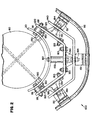
- Figure 2 is a bottom view of the anchorage assembly of Figure 1.
-
- A preferred anchorage system constructed according to the principles of the present invention is designated as 100 in Figures 1-2. Generally speaking, the
system 100 is connected to asupport structure 90 and supports at least onesafety line system 100 is suitable for use as a component in horizontal safety line systems like those disclosed in U.S. Pat. No. 5,343,975 to Riches et al.; U.S. Pat. No. 5,279,385 to Riches et al.; U.S. Pat. No. 5,224,427 to Riches et al.; and U.S. Pat. No. 4,790,410 to Sharp et al.. - As shown in Figure 2, the
system 100 includes a firstcurved plate 110 having an arcuate profile when viewed from below. The profile is preferably configured to match or conform to the exterior of the support structure, which is depicted as acylindrical post 90. Each end of theplate 110 is secured to thepost 90 by means of a respective fastener designated as 180 (and including a mating nut and bolt). Each associated bolt extends through a respective hole in theplate 110 and through arespective member 190, which preferably functions as both a spacer and an energy absorber. The respective holes in theplate 110 are offset vertically relative to one another to avoid interference between the respective bolts in the region of their intersection inside thepost 90. - As shown in Figure 2, a second
curved plate 120 has a somewhat U-shaped profile when viewed from below. However, the opposite distal ends of theplate 120 extend in divergent fashion and preferably define an angle equal to the change in direction experienced by thesafety line 160, 161 (approximately 110° on the depicted embodiment 100). Each distal end of thesecond plate 120 is secured to a respective end of thefirst plate 110 by means of a respective fastener 181 (including a mating nut and bolt). Each associated bolt extends through aligned holes in theplates respective member 191 disposed between theplates second plate 120 is similarly connected to an intermediate portion of thefirst plate 110, with a relativelylonger member 192 disposed therebetween, and a relatively longer fastener 182 (including a mating nut and bolt) inserted through themember 192 and interconnected between theplates members 190, themembers - As shown in Figure 2, a third
curved plate 140 has a profile comparable to that of thesecond plate 120. Each distal end of thethird plate 140 is secured to a respective end of thesecond plate 120 by means of a bowl-shaped bracket 130 disposed therebetween. At each end, fasteners 183 (including mating nuts and bolts) are interconnected between thesecond plate 120 and a rim portion of arespective bracket 130, and a fastener 184 (including a mating nut and bolt) is interconnected between thethird plate 140 and a base portion of arespective bracket 130. - Each
fastener 184 also secures arespective bracket 151 to theplate 140. Theplate 140 is relative taller than theplate 120, in order to accommodate the second set ofbrackets 150, which are secured in place byrespective fasteners 185. However, the present invention is not limited to any particular number of safety lines. Thebrackets safety lines brackets system 100 is constructed so that the members 190-192 are the first, and ideally the only, components to deform in response to a fall or any comparable load on eitherline plates brackets 150 and 151 (and the associated hassles) is a less frequent concern. - Those skilled in the art will recognize that the
system 100 may alternatively be constructed with brackets that are designed to deform. In other words, deformable brackets identical to those disclosed in U.S. Pat. No. 5,343,975 to Riches et al. may be used in thesystem 100 to provide an alternative system where the line supporting brackets are the first components to deform. - In yet another alternative arrangement, otherwise deformable brackets, like those disclosed in U.S. Pat. No. 5,343,975 to Riches et al., may be modified or reinforced to resist deformation. For example, reinforcing plates may be interconnected between the
brackets plate 140. The plates are preferably configured to match the profile of thebrackets 150 and 151 (including the relatively thin neck portion but not the tubular line supporting portion). The plates 170 are preferably made of stainless steel and welded to both thebrackets plate 140. With the addition of the plates, the members 190-192 would, once again, be the first components of the system to deform. - The present invention also provides various methods which may be performed in assembling and/or using the
system 100. This disclosure will enable others to realize various embodiments and/or applications. Therefore, although the present invention is described with reference to a preferred embodiment and a particular application, the scope of the present invention should be limited only to the extent of the following claims.
Claims (12)
- A method of routing an intermediate portion of a safety line about a comer on a support structure while accommodating passage of a slotted coupling member along the safety line, comprising the steps of:disposing at least two energy absorbers (190) between the support structure (90) and a first curved plate (110);securing the first curved plate (110) to the support structure;disposing at least two energy absorbers (191) between the first curved plate (110) and a second curved plate (120);securing the second curved plate (120) to the first curved plate (110);securing at least three line supporting brackets (150, 151) to the second curved plate;securing the safety line (160, 161) to the brackets; andsecuring the coupling member to the safety line.
- The method of claim 1, wherein a third curved plate (140) is interconnected between the second curved plate (120) and the brackets (150, 151), and bowl-shaped fasteners are interconnected between the third curved plate (140) and the second curved plate (120).
- The method of claim 1 or 2, wherein the energy absorbers (191) are designed to deform more readily than the plates or the brackets.
- The method of any preceding claim, wherein each of the energy absorbers (190) is configured to receive a respective bolt.
- The method of any preceding claim, wherein the first curved plate (110) is provided with a first contour, and the second curved plate (120) is provided with a discrete, second contour.
- An anchorage assembly for routing an intermediate portion of a safety line about a comer of a support structure while accommodating passage of a coupling device, comprising:a first curved plate (110) having a convex side and a concave side;an energy absorber (190) disposed adjacent the concave side proximate each end of the first curved plate (110);an energy absorber (191) disposed adjacent the convex side proximate each end of the first curved plate;a second curved plate (120) having a convex side and a concave side, wherein the concave side of the second curved plate (120) is arranged to face the convex side of the first curved plate (110), and the second curved plate (120) is bolted to the first curved plate (110); anda plurality of line supporting brackets (150, 151) anchored relative to the second curved plate, wherein the brackets are relatively more rigid than the energy absorbers.
- The anchorage assembly of claim 6, further comprising a third curved plate (140) interconnected between the second curved plate (120) and the line supporting brackets (150, 151).
- The anchorage assembly of claim 6 or 7, further comprising isolation brackets (130) interconnected between the third curved plate (140) and the second curved plate (120).
- The anchorage assembly of any of claims 6 to 8, wherein an additional energy absorber (192) is secured between an intermediate portion of the first curved plate (110) and an intermediate portion of the second curved plate (120).
- The anchorage assembly of any of claims 6 to 9, wherein a respective fastener extends through each energy absorber disposed adjacent the concave side of the first curved plate.
- The assembly of claim 6 or 7, wherein at least one curved plate is arcuate, and at least one curved plate is comprised of planar segments.
- The anchorage assembly of claim 7, wherein between the second and third plates there are provided fasteners (183) which include a bowl-shaped bracket (130) having a rim and a base, bolts interconnected between the rim and the second curved plate (120), and a bolt interconnected between the base, the third curved plate (140), and a respective one of the line supporting brackets (151).
Applications Claiming Priority (2)
| Application Number | Priority Date | Filing Date | Title |
|---|---|---|---|
| US26107201P | 2001-01-11 | 2001-01-11 | |
| US261072P | 2001-01-11 |
Publications (2)
| Publication Number | Publication Date |
|---|---|
| EP1222944A1 EP1222944A1 (en) | 2002-07-17 |
| EP1222944B1 true EP1222944B1 (en) | 2004-06-09 |
Family
ID=22991835
Family Applications (1)
| Application Number | Title | Priority Date | Filing Date |
|---|---|---|---|
| EP02250212A Expired - Lifetime EP1222944B1 (en) | 2001-01-11 | 2002-01-11 | Safety line anchorage methods and apparatus |
Country Status (6)
| Country | Link |
|---|---|
| US (3) | US6604605B2 (en) |
| EP (1) | EP1222944B1 (en) |
| AT (1) | ATE268626T1 (en) |
| AU (1) | AU777138B2 (en) |
| CA (1) | CA2367234A1 (en) |
| DE (1) | DE60200589T2 (en) |
Families Citing this family (21)
| Publication number | Priority date | Publication date | Assignee | Title |
|---|---|---|---|---|
| AU2004281075B2 (en) * | 2003-10-14 | 2011-02-24 | Safetylink Pty Ltd | Anchor assembly for safety device |
| WO2005037378A1 (en) * | 2003-10-14 | 2005-04-28 | Poldmaa, Kathleen | Anchor assembly for safety device |
| US20050269154A1 (en) * | 2004-06-04 | 2005-12-08 | John Siemienowicz | Alien fall arrest safety system |
| US20100187040A1 (en) * | 2004-06-04 | 2010-07-29 | Siemienowicz John R | Fall arrest safety system |
| US7416054B2 (en) * | 2004-10-25 | 2008-08-26 | James Liggett | Cable hook tracking system |
| US20090260919A1 (en) * | 2005-05-13 | 2009-10-22 | Latchways Plc. | Safety line anchor |
| FR2886164B1 (en) * | 2005-05-24 | 2007-07-13 | Capital Safety Group Emea Sa | DEVICE FOR SUPPORTING A SAFETY LINE |
| BE1016931A4 (en) * | 2005-06-14 | 2007-10-02 | Exponent Challenge Technology | IMPROVED MULTIPLE FALL PROTECTION WITH FLEXIBLE ANCHOR LINE. |
| FR2888298B1 (en) * | 2005-07-07 | 2007-09-28 | L R Etanco Soc Par Actions Sim | ANGLE RETURN DEVICE FOR CABLES SUCH AS SECURITY CABLES. |
| DE202005014358U1 (en) * | 2005-09-12 | 2005-11-17 | Skylotec Gmbh | Corner unit for safety unit e.g. safety rope, has fastening device designed as single piece with fall damper, which absorbs part of drop energy effected on corner unit when catching falling person by guard rail |
| US20080202849A1 (en) * | 2007-02-20 | 2008-08-28 | Michael Russo | Billboard fall arrest system |
| JP5113906B2 (en) * | 2007-06-13 | 2013-01-09 | エクスポーネント チャレンジ テクノロジー コーポラティエベ フェンノートシャプ メット ベペルクテ アーンスプラケリジュクヘイド | Fall prevention assembly |
| US8387752B2 (en) * | 2009-06-10 | 2013-03-05 | Paul Lagerstedt | Replaceable utility pole anchor system |
| US8746402B2 (en) * | 2010-08-06 | 2014-06-10 | Steven Christopher Nichols, Jr. | Devices, systems and methods relating to fall protection anchorage for over head and roofing installation featuring evacuation from service |
| AU2012246749A1 (en) | 2011-04-18 | 2013-10-31 | Troy GARLAND | Zip track system |
| US10105564B2 (en) | 2015-12-18 | 2018-10-23 | Ropes Courses, Inc. | Challenge course with return track |
| US20180347610A1 (en) * | 2017-06-05 | 2018-12-06 | Zebulon Zuk | Fasteners for roadbed construction |
| CN110279342B (en) * | 2018-03-19 | 2024-10-01 | 科沃斯家用机器人有限公司 | Robot safety system for wiping a glazing |
| USD952451S1 (en) | 2019-03-21 | 2022-05-24 | Zebulon Zuk | Fastener for roadbed construction |
| WO2021041708A1 (en) * | 2019-08-28 | 2021-03-04 | Oshkosh Corporation | Fall arrest system |
| US11833375B2 (en) * | 2020-02-21 | 2023-12-05 | Engineered Supply | Lifeline bypass shuttle |
Family Cites Families (12)
| Publication number | Priority date | Publication date | Assignee | Title |
|---|---|---|---|---|
| US3313567A (en) * | 1965-02-23 | 1967-04-11 | Sturman Oded Eddie | Belleville spring biased bumper |
| FR2415774A1 (en) * | 1978-01-30 | 1979-08-24 | Commissariat Energie Atomique | INERTIA WHEEL PROTECTION DEVICE |
| DE3322298C1 (en) | 1983-06-21 | 1984-07-19 | Söll KG Industrieschmiede, 8670 Hof | Device for moving a climbing protection device from a first climbing path to a second climbing path |
| GB8630787D0 (en) | 1986-12-23 | 1987-02-04 | Barrow Hepburn Equip Ltd | Fall-arrest cable attachments |
| GB9011370D0 (en) | 1990-05-22 | 1990-07-11 | Barrow Hepburn Sala Ltd | Energy-absorbing bracket |
| GB9110900D0 (en) | 1991-05-21 | 1991-07-10 | Barrow Hepburn Sala Ltd | Safety apparatus |
| US5718095A (en) * | 1994-03-11 | 1998-02-17 | Mm Systems Of Arizona | Method and device for attenuating vibration |
| US5445348A (en) * | 1994-09-12 | 1995-08-29 | Reliable Bethea Power Products, Inc. | Auxiliary cable attachment |
| US5979599A (en) | 1996-12-17 | 1999-11-09 | Noles; Larry J. | Track transport system, track-support bracket, and track-traveling apparatus |
| DE29719485U1 (en) | 1997-11-03 | 1999-03-18 | Söll GmbH, 95028 Hof | Fall protection |
| US6217090B1 (en) * | 1999-02-19 | 2001-04-17 | Mohammed Berzinji | Safety bumpers |
| DE29905756U1 (en) | 1999-03-05 | 2000-08-03 | Söll GmbH, 95028 Hof | Holder for the guide device of a fall protection and fall protection with such a holder |
-
2001
- 2001-12-19 US US10/026,926 patent/US6604605B2/en not_active Expired - Fee Related
- 2001-12-28 AU AU97508/01A patent/AU777138B2/en not_active Ceased
-
2002
- 2002-01-08 CA CA002367234A patent/CA2367234A1/en not_active Abandoned
- 2002-01-11 EP EP02250212A patent/EP1222944B1/en not_active Expired - Lifetime
- 2002-01-11 DE DE60200589T patent/DE60200589T2/en not_active Expired - Fee Related
- 2002-01-11 AT AT02250212T patent/ATE268626T1/en not_active IP Right Cessation
-
2003
- 2003-06-03 US US10/453,431 patent/US6736239B2/en not_active Expired - Fee Related
- 2003-06-03 US US10/453,352 patent/US6802390B2/en not_active Expired - Fee Related
Also Published As
| Publication number | Publication date |
|---|---|
| US20020125069A1 (en) | 2002-09-12 |
| US6604605B2 (en) | 2003-08-12 |
| AU777138B2 (en) | 2004-10-07 |
| DE60200589D1 (en) | 2004-07-15 |
| ATE268626T1 (en) | 2004-06-15 |
| AU9750801A (en) | 2002-07-18 |
| DE60200589T2 (en) | 2005-07-14 |
| US20030192740A1 (en) | 2003-10-16 |
| US20030192739A1 (en) | 2003-10-16 |
| EP1222944A1 (en) | 2002-07-17 |
| US6802390B2 (en) | 2004-10-12 |
| US6736239B2 (en) | 2004-05-18 |
| CA2367234A1 (en) | 2002-07-11 |
Similar Documents
| Publication | Publication Date | Title |
|---|---|---|
| US6604605B2 (en) | Safety line anchorage methods and apparatus | |
| EP0435441B1 (en) | Vehicle crash barrier with friction brake | |
| US4766708A (en) | Shock and vibration resistant structures | |
| US5358068A (en) | Safety system including cable tensioner and shock absorber | |
| US5297888A (en) | Tubular framing system | |
| US5380042A (en) | Protective cage for fuel tank installed between vehicle side members | |
| US5516179A (en) | Truck bed seat | |
| AU728573B1 (en) | Safety line anchorage methods and apparatus | |
| AU643293B2 (en) | Fall-arrest systems | |
| JPH08209633A (en) | Shock damper | |
| US20060272891A1 (en) | Stanchion for a horizontal lifeline system | |
| EP2522400A2 (en) | Support post assembly for a safety line system | |
| WO2021030111A1 (en) | Column-to-beam connection systems including a shear component | |
| US5105907A (en) | Fall restraint cable support and method | |
| US5002152A (en) | Fall restraint cable support and method | |
| EP0415555B1 (en) | A collapsible steering column assembly | |
| EP1262612A2 (en) | Temporary guard rail | |
| CN117513552B (en) | Prefabricated modularized building earthquake-resistant structure and construction method thereof | |
| US20020129993A1 (en) | Safety harness and ladder assembly | |
| CN112065030A (en) | Wall attaching support, wall attaching device and using method thereof | |
| EP1926533B1 (en) | Energy absorber | |
| US5388797A (en) | Swing set hang tube protective mounting bracket | |
| CN218293093U (en) | Novel quick-release assembly type railing | |
| AU2004200724B2 (en) | Energy absorbing device | |
| GB2490873A (en) | Adjustable safety line mounting with various orientations |
Legal Events
| Date | Code | Title | Description |
|---|---|---|---|
| PUAI | Public reference made under article 153(3) epc to a published international application that has entered the european phase |
Free format text: ORIGINAL CODE: 0009012 |
|
| AK | Designated contracting states |
Kind code of ref document: A1 Designated state(s): AT BE CH CY DE DK ES FI FR GB GR IE IT LI LU MC NL PT SE TR |
|
| AX | Request for extension of the european patent |
Free format text: AL;LT;LV;MK;RO;SI |
|
| RIN1 | Information on inventor provided before grant (corrected) |
Inventor name: MOY, RUSSELL I. Inventor name: VONG, PAUL Inventor name: PETERSON, GREGORY K. |
|
| 17P | Request for examination filed |
Effective date: 20020911 |
|
| 17Q | First examination report despatched |
Effective date: 20021111 |
|
| AKX | Designation fees paid |
Designated state(s): AT BE CH CY DE DK ES FI FR GB GR IE IT LI LU MC NL PT SE TR |
|
| GRAP | Despatch of communication of intention to grant a patent |
Free format text: ORIGINAL CODE: EPIDOSNIGR1 |
|
| GRAS | Grant fee paid |
Free format text: ORIGINAL CODE: EPIDOSNIGR3 |
|
| GRAA | (expected) grant |
Free format text: ORIGINAL CODE: 0009210 |
|
| RIN1 | Information on inventor provided before grant (corrected) |
Inventor name: MOY, RUSSELL I. Inventor name: VONG, PAUL Inventor name: PETERSON, GREGORY K. |
|
| AK | Designated contracting states |
Kind code of ref document: B1 Designated state(s): AT BE CH CY DE DK ES FI FR GB GR IE IT LI LU MC NL PT SE TR |
|
| PG25 | Lapsed in a contracting state [announced via postgrant information from national office to epo] |
Ref country code: TR Free format text: LAPSE BECAUSE OF FAILURE TO SUBMIT A TRANSLATION OF THE DESCRIPTION OR TO PAY THE FEE WITHIN THE PRESCRIBED TIME-LIMIT Effective date: 20040609 Ref country code: LI Free format text: LAPSE BECAUSE OF FAILURE TO SUBMIT A TRANSLATION OF THE DESCRIPTION OR TO PAY THE FEE WITHIN THE PRESCRIBED TIME-LIMIT Effective date: 20040609 Ref country code: IT Free format text: LAPSE BECAUSE OF FAILURE TO SUBMIT A TRANSLATION OF THE DESCRIPTION OR TO PAY THE FEE WITHIN THE PRESCRIBED TIME-LIMIT;WARNING: LAPSES OF ITALIAN PATENTS WITH EFFECTIVE DATE BEFORE 2007 MAY HAVE OCCURRED AT ANY TIME BEFORE 2007. THE CORRECT EFFECTIVE DATE MAY BE DIFFERENT FROM THE ONE RECORDED. Effective date: 20040609 Ref country code: FI Free format text: LAPSE BECAUSE OF FAILURE TO SUBMIT A TRANSLATION OF THE DESCRIPTION OR TO PAY THE FEE WITHIN THE PRESCRIBED TIME-LIMIT Effective date: 20040609 Ref country code: CH Free format text: LAPSE BECAUSE OF FAILURE TO SUBMIT A TRANSLATION OF THE DESCRIPTION OR TO PAY THE FEE WITHIN THE PRESCRIBED TIME-LIMIT Effective date: 20040609 Ref country code: BE Free format text: LAPSE BECAUSE OF FAILURE TO SUBMIT A TRANSLATION OF THE DESCRIPTION OR TO PAY THE FEE WITHIN THE PRESCRIBED TIME-LIMIT Effective date: 20040609 Ref country code: AT Free format text: LAPSE BECAUSE OF FAILURE TO SUBMIT A TRANSLATION OF THE DESCRIPTION OR TO PAY THE FEE WITHIN THE PRESCRIBED TIME-LIMIT Effective date: 20040609 |
|
| REG | Reference to a national code |
Ref country code: GB Ref legal event code: FG4D |
|
| REG | Reference to a national code |
Ref country code: CH Ref legal event code: EP |
|
| REF | Corresponds to: |
Ref document number: 60200589 Country of ref document: DE Date of ref document: 20040715 Kind code of ref document: P |
|
| REG | Reference to a national code |
Ref country code: IE Ref legal event code: FG4D |
|
| RAP2 | Party data changed (patent owner data changed or rights of a patent transferred) |
Owner name: ADVENTURE SYSTEMS INC Owner name: CAPITAL SAFETY GROUP (AUSTRALIA) PTY LIMITED |
|
| PG25 | Lapsed in a contracting state [announced via postgrant information from national office to epo] |
Ref country code: SE Free format text: LAPSE BECAUSE OF FAILURE TO SUBMIT A TRANSLATION OF THE DESCRIPTION OR TO PAY THE FEE WITHIN THE PRESCRIBED TIME-LIMIT Effective date: 20040909 Ref country code: GR Free format text: LAPSE BECAUSE OF FAILURE TO SUBMIT A TRANSLATION OF THE DESCRIPTION OR TO PAY THE FEE WITHIN THE PRESCRIBED TIME-LIMIT Effective date: 20040909 Ref country code: DK Free format text: LAPSE BECAUSE OF FAILURE TO SUBMIT A TRANSLATION OF THE DESCRIPTION OR TO PAY THE FEE WITHIN THE PRESCRIBED TIME-LIMIT Effective date: 20040909 |
|
| PG25 | Lapsed in a contracting state [announced via postgrant information from national office to epo] |
Ref country code: ES Free format text: LAPSE BECAUSE OF FAILURE TO SUBMIT A TRANSLATION OF THE DESCRIPTION OR TO PAY THE FEE WITHIN THE PRESCRIBED TIME-LIMIT Effective date: 20040920 |
|
| NLT2 | Nl: modifications (of names), taken from the european patent patent bulletin |
Owner name: CAPITAL SAFETY GROUP (AUSTRALIA) PTY LIMITED EN AD |
|
| REG | Reference to a national code |
Ref country code: CH Ref legal event code: PL |
|
| PGFP | Annual fee paid to national office [announced via postgrant information from national office to epo] |
Ref country code: DE Payment date: 20050106 Year of fee payment: 4 |
|
| PGFP | Annual fee paid to national office [announced via postgrant information from national office to epo] |
Ref country code: FR Payment date: 20050110 Year of fee payment: 4 |
|
| PG25 | Lapsed in a contracting state [announced via postgrant information from national office to epo] |
Ref country code: LU Free format text: LAPSE BECAUSE OF NON-PAYMENT OF DUE FEES Effective date: 20050111 Ref country code: IE Free format text: LAPSE BECAUSE OF NON-PAYMENT OF DUE FEES Effective date: 20050111 Ref country code: CY Free format text: LAPSE BECAUSE OF FAILURE TO SUBMIT A TRANSLATION OF THE DESCRIPTION OR TO PAY THE FEE WITHIN THE PRESCRIBED TIME-LIMIT Effective date: 20050111 |
|
| PG25 | Lapsed in a contracting state [announced via postgrant information from national office to epo] |
Ref country code: MC Free format text: LAPSE BECAUSE OF NON-PAYMENT OF DUE FEES Effective date: 20050131 |
|
| ET | Fr: translation filed | ||
| PLBE | No opposition filed within time limit |
Free format text: ORIGINAL CODE: 0009261 |
|
| STAA | Information on the status of an ep patent application or granted ep patent |
Free format text: STATUS: NO OPPOSITION FILED WITHIN TIME LIMIT |
|
| 26N | No opposition filed |
Effective date: 20050310 |
|
| REG | Reference to a national code |
Ref country code: IE Ref legal event code: MM4A |
|
| PG25 | Lapsed in a contracting state [announced via postgrant information from national office to epo] |
Ref country code: GB Free format text: LAPSE BECAUSE OF NON-PAYMENT OF DUE FEES Effective date: 20060111 |
|
| PG25 | Lapsed in a contracting state [announced via postgrant information from national office to epo] |
Ref country code: FR Free format text: LAPSE BECAUSE OF NON-PAYMENT OF DUE FEES Effective date: 20060131 |
|
| PG25 | Lapsed in a contracting state [announced via postgrant information from national office to epo] |
Ref country code: NL Free format text: LAPSE BECAUSE OF NON-PAYMENT OF DUE FEES Effective date: 20060801 Ref country code: DE Free format text: LAPSE BECAUSE OF NON-PAYMENT OF DUE FEES Effective date: 20060801 |
|
| GBPC | Gb: european patent ceased through non-payment of renewal fee |
Effective date: 20060111 |
|
| NLV4 | Nl: lapsed or anulled due to non-payment of the annual fee |
Effective date: 20060801 |
|
| REG | Reference to a national code |
Ref country code: FR Ref legal event code: ST Effective date: 20060929 |
|
| PG25 | Lapsed in a contracting state [announced via postgrant information from national office to epo] |
Ref country code: PT Free format text: LAPSE BECAUSE OF NON-PAYMENT OF DUE FEES Effective date: 20041109 |