EP1222616B1 - Optically-based methods and apparatus for sorting, coding, and authentication using a narrowband emission gain medium - Google Patents
Optically-based methods and apparatus for sorting, coding, and authentication using a narrowband emission gain medium Download PDFInfo
- Publication number
- EP1222616B1 EP1222616B1 EP00902359A EP00902359A EP1222616B1 EP 1222616 B1 EP1222616 B1 EP 1222616B1 EP 00902359 A EP00902359 A EP 00902359A EP 00902359 A EP00902359 A EP 00902359A EP 1222616 B1 EP1222616 B1 EP 1222616B1
- Authority
- EP
- European Patent Office
- Prior art keywords
- wavelength
- emission
- wavelengths
- document
- security
- Prior art date
- Legal status (The legal status is an assumption and is not a legal conclusion. Google has not performed a legal analysis and makes no representation as to the accuracy of the status listed.)
- Expired - Lifetime
Links
- 238000000034 method Methods 0.000 title claims abstract description 22
- 239000000758 substrate Substances 0.000 claims abstract description 62
- 230000003287 optical effect Effects 0.000 claims abstract description 29
- 230000002269 spontaneous effect Effects 0.000 claims description 16
- 238000001228 spectrum Methods 0.000 claims description 10
- 238000001514 detection method Methods 0.000 claims description 7
- 230000004044 response Effects 0.000 claims description 7
- 239000000463 material Substances 0.000 abstract description 26
- 230000005670 electromagnetic radiation Effects 0.000 abstract description 13
- 239000000835 fiber Substances 0.000 description 40
- 239000000975 dye Substances 0.000 description 30
- 229920000642 polymer Polymers 0.000 description 13
- 239000011248 coating agent Substances 0.000 description 9
- 238000000576 coating method Methods 0.000 description 9
- 230000008901 benefit Effects 0.000 description 6
- 239000011159 matrix material Substances 0.000 description 6
- 230000003595 spectral effect Effects 0.000 description 6
- 239000004753 textile Substances 0.000 description 4
- 230000009471 action Effects 0.000 description 3
- 238000010586 diagram Methods 0.000 description 3
- 239000011521 glass Substances 0.000 description 3
- 238000005286 illumination Methods 0.000 description 3
- 238000003384 imaging method Methods 0.000 description 3
- 238000010200 validation analysis Methods 0.000 description 3
- 229920002292 Nylon 6 Polymers 0.000 description 2
- GWEVSGVZZGPLCZ-UHFFFAOYSA-N Titan oxide Chemical compound O=[Ti]=O GWEVSGVZZGPLCZ-UHFFFAOYSA-N 0.000 description 2
- 239000002131 composite material Substances 0.000 description 2
- 230000005284 excitation Effects 0.000 description 2
- 230000007246 mechanism Effects 0.000 description 2
- 229910052751 metal Inorganic materials 0.000 description 2
- 239000002184 metal Substances 0.000 description 2
- 239000002245 particle Substances 0.000 description 2
- 229920000307 polymer substrate Polymers 0.000 description 2
- 230000008569 process Effects 0.000 description 2
- MUSLHCJRTRQOSP-UHFFFAOYSA-N rhodamine 101 Chemical compound [O-]C(=O)C1=CC=CC=C1C(C1=CC=2CCCN3CCCC(C=23)=C1O1)=C2C1=C(CCC1)C3=[N+]1CCCC3=C2 MUSLHCJRTRQOSP-UHFFFAOYSA-N 0.000 description 2
- DJWWHVKRLDNDJK-UHFFFAOYSA-N rhodamine 640 perchlorate Chemical compound [O-]Cl(=O)(=O)=O.OC(=O)C1=CC=CC=C1C(C1=CC=2CCCN3CCCC(C=23)=C1O1)=C2C1=C(CCC1)C3=[N+]1CCCC3=C2 DJWWHVKRLDNDJK-UHFFFAOYSA-N 0.000 description 2
- 238000009738 saturating Methods 0.000 description 2
- 239000004065 semiconductor Substances 0.000 description 2
- 239000002904 solvent Substances 0.000 description 2
- OVTCUIZCVUGJHS-VQHVLOKHSA-N trans-dipyrrin Chemical compound C=1C=CNC=1/C=C1\C=CC=N1 OVTCUIZCVUGJHS-VQHVLOKHSA-N 0.000 description 2
- VEXZGXHMUGYJMC-UHFFFAOYSA-M Chloride anion Chemical compound [Cl-] VEXZGXHMUGYJMC-UHFFFAOYSA-M 0.000 description 1
- OAICVXFJPJFONN-UHFFFAOYSA-N Phosphorus Chemical compound [P] OAICVXFJPJFONN-UHFFFAOYSA-N 0.000 description 1
- 238000004458 analytical method Methods 0.000 description 1
- 238000003491 array Methods 0.000 description 1
- 239000000470 constituent Substances 0.000 description 1
- 238000001816 cooling Methods 0.000 description 1
- 238000004043 dyeing Methods 0.000 description 1
- 230000000694 effects Effects 0.000 description 1
- 230000002708 enhancing effect Effects 0.000 description 1
- VYXSBFYARXAAKO-UHFFFAOYSA-N ethyl 2-[3-(ethylamino)-6-ethylimino-2,7-dimethylxanthen-9-yl]benzoate;hydron;chloride Chemical compound [Cl-].C1=2C=C(C)C(NCC)=CC=2OC2=CC(=[NH+]CC)C(C)=CC2=C1C1=CC=CC=C1C(=O)OCC VYXSBFYARXAAKO-UHFFFAOYSA-N 0.000 description 1
- 230000001747 exhibiting effect Effects 0.000 description 1
- 238000001125 extrusion Methods 0.000 description 1
- 239000011888 foil Substances 0.000 description 1
- 239000000976 ink Substances 0.000 description 1
- 238000004519 manufacturing process Methods 0.000 description 1
- 239000002159 nanocrystal Substances 0.000 description 1
- XJCPMUIIBDVFDM-UHFFFAOYSA-M nile blue A Chemical compound [Cl-].C1=CC=C2C3=NC4=CC=C(N(CC)CC)C=C4[O+]=C3C=C(N)C2=C1 XJCPMUIIBDVFDM-UHFFFAOYSA-M 0.000 description 1
- 229920001778 nylon Polymers 0.000 description 1
- 239000013307 optical fiber Substances 0.000 description 1
- 230000000737 periodic effect Effects 0.000 description 1
- 239000000049 pigment Substances 0.000 description 1
- 229920005594 polymer fiber Polymers 0.000 description 1
- 239000002952 polymeric resin Substances 0.000 description 1
- 230000001902 propagating effect Effects 0.000 description 1
- 230000005855 radiation Effects 0.000 description 1
- -1 rare earth ion Chemical class 0.000 description 1
- 229910052761 rare earth metal Inorganic materials 0.000 description 1
- 229910052710 silicon Inorganic materials 0.000 description 1
- 239000010703 silicon Substances 0.000 description 1
- 229920003002 synthetic resin Polymers 0.000 description 1
- 230000002123 temporal effect Effects 0.000 description 1
- 238000011179 visual inspection Methods 0.000 description 1
- XLYOFNOQVPJJNP-UHFFFAOYSA-N water Substances O XLYOFNOQVPJJNP-UHFFFAOYSA-N 0.000 description 1
- 238000002166 wet spinning Methods 0.000 description 1
Images


Classifications
-
- G—PHYSICS
- G07—CHECKING-DEVICES
- G07D—HANDLING OF COINS OR VALUABLE PAPERS, e.g. TESTING, SORTING BY DENOMINATIONS, COUNTING, DISPENSING, CHANGING OR DEPOSITING
- G07D7/00—Testing specially adapted to determine the identity or genuineness of valuable papers or for segregating those which are unacceptable, e.g. banknotes that are alien to a currency
- G07D7/06—Testing specially adapted to determine the identity or genuineness of valuable papers or for segregating those which are unacceptable, e.g. banknotes that are alien to a currency using wave or particle radiation
- G07D7/12—Visible light, infrared or ultraviolet radiation
- G07D7/1205—Testing spectral properties
Definitions
- This invention relates generally to optically-based methods and apparatus for performing sorting, coding and authentication of objects, such as paper or polymer based objects including currency, checks, negotiable instruments, passports, wills and other documents.
- a multi-phase gain medium including an emission phase (such as dye molecules) and a scattering phase (such as TiO 2 ).
- a third, matrix phase may also be provided in some embodiments. Suitable materials for the matrix phase include solvents, glasses and polymers.
- the gain medium is shown to provide a laser-like spectral linewidth collapse above a certain pump pulse energy.
- the gain medium is disclosed to be suitable for encoding objects with multiple-wavelength codes, and to be suitable for use with a number of substrate materials, including polymers and textiles.
- WO 98/45803 describes a method for authenticating a document including the steps of: (a) providing a document to be authenticated; (b) illuminating at least a portion of the document with laser light that exceeds a threshold fluence; (c) detecting a narrow band laser-like emission of at least one wavelength from the document in response to the step of illuminating; and declaring the document to be authentic only if laser-like emission is detected.
- a very advantageous solution to the various problems discussed above would be to provide a security structure that could be incorporated into the matrix that forms the document, currency, negotiable instrument, etc., wherein the structure could function to both authenticate the substrate as well as to enhance the countability and/or sortability of the substrate.
- the security structure should be small so that it can incorporated into substrates, low cost, and exhibit non-saturating or substantially non-saturating behavior that provides the structure with a high signal to noise output and a capability of being used in a non-contact, high speed mode of operation.
- An optically-based security structure in accordance with the teachings of this invention would enable such a non-contact, high speed mode of operation.
- a document or document substrate such as paper or a polymer
- ASE amplified spontaneous emission
- ASE amplified spontaneous emission
- a first aspect of the invention is directed to a method for processing a document, comprising the steps of: providing a document to be authenticated, the document comprising: a substrate and at least one device that is comprised of an optical gain medium and a structure coupled to said gain medium for at least one of (a) favoring the creation of at least one mode that favors at least one narrow band of wavelengths over other wavelengths to enable energy in the at least one narrow band of wavelengths to constructively add or (b) supporting amplified spontaneous emission, said at least one device encoding information that is made manifest by an emission from said device; illuminating at least a portion of the document with light selected for exciting the gain medium; detecting an emission of at least one wavelength from the document in response to the step of illuminating; and obtaining the information that was encoded in the device from the detected emission, wherein more than two signal levels are associated with each wavelength of the at least one wavelength.
- a second aspect of the invention is directed to apparatus for at least one of authenticating, sorting or counting documents, comprising: a light source for illuminating all or a portion of a document, the document comprising: a substrate and at least one device located in or on said substrate, said device being comprised of an optical gain medium and a structure for at least one of (a) favoring the creation of at least one mode that favors at least one narrow band of wavelengths over other wavelengths to enable energy in the at least one narrow band of wavelengths to constructively add or (b) supporting amplified spontaneous emission for outputting light of at least one wavelength, said light source outputting light having wavelengths that are predetermined to excite said gain medium; at least one detector responsive to said wavelength for detecting the presence of the at least one wavelength; and decision logic, having an input coupled to an output of said at least one detector, for at least one of indicating the authenticity of the document based at least in part on a detection of the at least one wavelength, for counting the document based at least in part on a detection of the at least
- a third aspect of the invention is directed to a security device for use with a substrate and comprising: a gain medium coupled to a structure for at least one of (a) favoring the creation of at least one mode that favors at least one narrow band of wavelengths over other wavelengths to enable energy in the at least one narrow band of wavelengths to constructively add or (b) supporting amplified spontaneous emission, wherein said structure is comprised of at least one of a monolithic structure, a multi-layered structure, or an ordered structure that provides distributed optical feedback for the creation of said at least one mode, wherein more than two signal levels are associated with each wavelength of the at least one wavelength.
- the apparatus includes a laser or some other light source for illuminating all or a portion of a document.
- the document includes a substrate and at least one security structure or device located in or on the substrate.
- the security structure includes, in one embodiment, a gain medium coupled to a structure that supports the creation of at least one mode for electromagnetic radiation.
- the security structure includes, in another embodiment, a gain medium coupled to a structure having a dimension or length in one or more directions to produce and support amplified spontaneous emission (ASE).
- ASE amplified spontaneous emission
- a security device in accordance with this invention has a structure with boundaries whose geometry and material properties (e.g., index of refraction) support an enhancement of electromagnetic radiation that may be emitted from a gain medium, such as a dye and/or semiconductor particles, that is also contained within the device.
- the structure may be provided so as to favor the creation of at least one mode so as to enhance electromagnetic radiation within a narrow band of wavelengths.
- Suitable shapes for the structure include, but are not limited to, elongated generally cylindrical shapes such as filaments, spheres, half-spheres, toroids, cubes and other polyhedral shapes, as well a disks.
- the structures may be monolithic structures or multi-layered structures, or a combination of same.
- the security devices containing the structures are of a size compatible with the dimensions of the substrate or carrier into which they are placed, such as paper or thin polymer sheets such as those used for credit cards, debit cards and identification cards, such as driver's licenses.
- a laser source may output light having wavelengths that are predetermined to excite the gain medium.
- Apparatus that comprises the laser further includes at least one photodetector, or an array of photodetectors, that is responsive to at least one predetermined wavelength, and decision logic for at least one of indicating the authenticity of a document containing the security device, for counting the document, or for sorting the document.
- the decision logic operates based at least in part on a detection of the at least one predetermined wavelength or on the absence of at least one predetermined wavelength.
- the decision process for authentication may include the linewidth and other spectral features of the signature, such as its derivative. These parameters may be employed to further corroborate the presence of a lasing emission signature.
- a document could be a currency, or a passport, or a lottery ticket, or a negotiable security, or a credit card or a debit card, or an identification card such as a driver's license or employee's badge, or any substrate or carrier which it is desired to authenticate, count, encode with information, sort and/or verify.
- This invention employs security structures that contain an optical gain medium that is capable of exhibiting laser-like activity (e.g., emission in a narrow band of wavelengths when excited by a source of excitation energy).
- an optical gain medium that is capable of exhibiting laser-like activity (e.g., emission in a narrow band of wavelengths when excited by a source of excitation energy).
- the security structures in accordance with the teachings of this invention do not require the presence of a scattering phase or scattering sites to generate the narrow band of emissions.
- the optical gain medium that provides the amplified spontaneous emission in response to the illumination is responsive to, for example, size constraints, structural constraints, geometry constraints, and/or index of refraction mis-matches for emitting the narrow band of emissions.
- the size constraints, structural constraints, geometry constraints, and/or index of refraction mis-matches are used to provide for at least one mode in the security structure that favors at least one narrow band of wavelengths over other wavelengths, enabling emitted energy in the narrow band of wavelengths to constructively add.
- the size constraints, structural constraints, geometry constraints, and/or index of refraction mis-matches are used to provide for an occurrence of amplified spontaneous emission (ASE) in response to the step of illuminating. It should be noted that one may provide ASE within a mode, but that one does not require a mode to have ASE. In general, the ASE can occur in homogeneously and inhomogeneously broadened medium.
- the security structure is thus comprised of a matrix phase, for example a polymer or solvent, that is substantially transparent at wavelengths of interest, and an electromagnetic radiation amplifying (gain) phase, for example a dye or a rare earth ion.
- the amplifying (gain) phase is placed within a structure, in accordance with the teachings of this invention, where the structure has a predetermined size, or structural features, or geometry, and/or an index of refraction that differs from the index of refraction of the substrate within which the security structure is intended for use.
- the structure tends to confine and possibly guide the electromagnetic radiation output from the amplifying (gain) phase, and may favor the creation of at least one mode, or the creation of amplified spontaneous emission (ASE).
- the output may be contained in a narrow range of wavelengths, e.g., a few nanometers in width, and is considered herein as a narrowband emission.
- the matrix phase may comprise the material that forms the security structure, such as a polymeric planchette that contains the electromagnetic radiation amplifying (gain) phase.
- a "security device” or “security structure” is intended to mean an object that is fabricated in accordance with this invention and which has dimensions suitable for being included within a desired substrate material, such as the paper of currency or a passport. Whether the object is intended for use in authenticating the substrates, or for counting the substrates, or for sorting the substrates, or for any combination of authentication, counting or sorting, the object is still referred to herein for convenience as a "security structure".
- the document or substrate containing the security structure or device could be, but is not limited to, a currency, or a passport, or a lottery ticket, or a negotiable security, or a credit card or a debit card, or an identification card, such as a driver's license or employee's badge, or any substrate or carrier which it is desired to authenticate, count, encode, sort and/or verify.
- This invention may also enable both public validation, e.g., by visual inspection, and machine-based validation, e.g., with the use of an optical source and one or more suitable optical detectors. Thus, two levels of authentication can be used.
- FIG. 1 illustrates a first embodiment of this invention.
- a document including any paper, paper-containing, or polymer substrate 10, includes a plurality of embedded elongated bodies or threads 12 that include a host material, such as a textile fiber or a polymer fiber, that is coated or impregnated with a dye or some other material capable of amplifying light.
- the threads 12 exhibit electro-optic properties consistent with laser action; i.e., an output emission that exhibits both a spectral linewidth collapse and a temporal collapse at an input pump energy above a threshold level.
- the threads 12 In response to illumination with laser light, such as frequency doubled light (i.e., 532 nm) from a Nd:YAG laser 14, the threads 12 emit a wavelength ⁇ that is characteristic of the chromic dye or other material that comprises the illuminated threads 12.
- a reflective coating can be applied so as to enhance the emission from the threads 12.
- An optical detector 16 which may include a wavelength selective filter, can be used to detect the emission at the wavelength ⁇ . The emission may also be detected visually, assuming that it lies within the visible portion of the spectrum. In either case, the detection of the emission at the characteristic wavelength ⁇ indicates that the document is an authentic document, i.e., one printed on the substrate 10 having the threads 12. It is assumed that only authentic documents are printed on such substrates, and that one wishing to fraudulently produce such a document would not have access to the substrate material.
- Currency is one specific example.
- Fig. 7 illustrates a number of exemplary dyes that are suitable for practicing this invention, and shows their relative energy output as a function of wavelength.
- the teaching of this invention is not limited for use with only the dyes listed in Fig. 7 .
- Fig. 2A is an enlarged elevational view of a small disk-shaped security structure, also referred to as a planchette 12A.
- the planchette 12A has, by example, a circular cylindrical shape with a diameter (D) and a thickness (T) that is less than the dimensions of the substrate material to which the planchette will be added.
- D diameter
- T thickness
- U.S. currency has a thickness of about 100 microns
- D and T will both be significantly less than 100 microns.
- T and nD the perimeter, can be chosen to have values that are a function of a desired emission wavelength, such as one half wavelength or some multiple of one half wavelength.
- the planchette 12A is comprised of a polymer, or a glass, or some other suitable material, which contains an optical amplifying (gain) material, such as one of the dyes shown in Fig. 7 .
- One surface of the planchette 12A may be provided with a reflective coating. It is also preferred that the index of refraction (n) of the planchette 12A be different from the index of refraction (n') of the desired substrate material (i.e., the planchette 12A is non-index matched to the surrounding substrate.)
- a planchette can also be designed so that ASE across the thickness T creates a narrowband emission, or such that ASE along an internal reflection path, such as the perimeter, leads to narrowband emission.
- Fig. 2B depicts a fiber embodiment of the security structure, wherein the diameter (DM) of fiber 12B is made to have a value that is a function of the desired emission wavelength, such as one half wavelength or some multiple of one half wavelength.
- the fiber 12B is comprised of a polymer, or a glass, or some other suitable material, which contains an optical emitter, such as one of the dyes shown in Fig. 7 .
- the index of refraction (n) of the fiber 12B be different from the index of refraction (n') of the desired substrate material so that the fiber 12B is non-index matched to the surrounding substrate.
- the electromagnetic radiation that is emitted by the dye is confined to the fiber and propagates therein. Due at least in part to the diameter of the fiber 12B one narrowband of wavelengths is preferred over other wavelengths, and energy in this band of wavelengths builds over time, relative to the other wavelengths.
- the diameter DM is made a function of the emission wavelength of the selected dye. The end result is a narrowband emission from the fiber 12B, when the dye contained in the matrix material of the fiber 12B is stimulated by an external laser source.
- Fig. 2C depicts a DFB embodiment of the security structure, wherein a periodic structure comprised of regions of first and second indices of refraction (n 1 and n 2 ) alternate along the length of the DFB structure 12C.
- n 1 is not equal to n 2
- n' are equal to n'.
- the thickness of each of the regions may be one quarter wavelength, or a multiple of one quarter wavelength, of the desired emission wavelength to provide a mode for the desired emission wavelength.
- Fig. 5 depicts the emission peak of the selected dye in any of the embodiments of Figs. 2A-2E , before (B) and after (A) the spectral collapse made possible by the security structure having a predetermined size, or structural features, or geometry, and/or an index of refraction that differs from the index of refraction of the substrate within which the security structure is intended for use.
- the structure can include a propagating mode, and the mode can help guide the electromagnetic radiation, but the mode is not necessary for ASE to occur.
- Fig. 2D illustrates a top view of a planchette 12A, as in Fig. 2A , or an end view of fiber 12B, wherein the planchette or fiber is sectored (e.g., four sectors) and is capable of outputting multiple wavelengths ( ⁇ 1 - ⁇ 4 ).
- Fig. 2E illustrates a top view of a planchette 12A, as in Fig. 2A , or an end view of fiber 12B, wherein the planchette or fiber is radially structured so as to be capable of outputting multiple wavelengths.
- Such multiple wavelength embodiments lend themselves to the wavelength encoding of information, as will be described in further detail below.
- Fig. 3 illustrates an embodiment of a structure wherein a one or more regions (e.g. three) 22, 24, 26 each include, by example, one or more dyes either alone or in combination with one or more rare earths that are selected for providing a desired wavelength ⁇ 1 , ⁇ 2 , ⁇ 3 .
- An underlying substrate such as a thin transparent polymer layer 28, overlies a reflective layer 30.
- the reflective layer 30 can be a thin layer of metal foil, and may be corrugated or otherwise shaped or patterned as desired.
- the structure can be cut into thin strips which can be used to form the threads 12 shown in Fig. 1 .
- a public authentication can be provided based on a characteristic broad band fluorescent emission (e.g., some tens of nanometers or greater) of the dye and/or phosphor particles.
- a characteristic broad band fluorescent emission e.g., some tens of nanometers or greater
- the structure when excited by the laser 14 the structure emits a characteristic narrowband emission (e.g., less than about 10 nm) at each of the wavelengths ⁇ 1 , ⁇ 2 , ⁇ 3 .
- the presence of these three wavelengths can be detected with the detector or detectors 16, in combination with suitable optical passband filters (see also Fig. 8 ), thereby providing also a machine readable authentication of the document containing the structure.
- a spectrum analyzer such as monolithic detector array with, by example, an optical wedge can be used to detect the spectrum.
- the output of the spectrum analyzer is then analyzed for detecting ⁇ peaks and derivatives, and can be compared to a predetermined look-up table.
- a suitable coating 32 can be applied to the regions 22, 24 and 26.
- the coating 32 can provide UV stability and/or protection from abrasive forces.
- a thin transparent UV absorbing polymer coating is one suitable example, as are dyes, pigments and phosphors.
- the coating can be selected to be or contain a fluorescent material.
- the coating 32 can be excited with a UV source to provide the public authentication function.
- the threads 12 may be comprised of fibers such as nylon-6, nylon 6/6, PET, ABS, SAN, and PPS.
- a selected dye may be selected from Pyrromethene 567, Rhodamine 590 chloride, and Rhodamine 640 perchlorate.
- the selected dye may be compounded with a selected polymer resin and then extruded. Wet spinning is another suitable technique for forming the fibers.
- a suitable dye concentration is 2 X 10 -3 M. Extrusion at 250°C followed by cooling in a water bath is one suitable technique for forming the fibers 12. When used in a paper substrate the diameter is sized accordingly, and in accordance with the selected emission wavelength.
- a suitable excitation (pump 12) fluence is in the range about 5 mJ/cm 2 and greater.
- Two or more fibers, each containing a different dye, can be braided together or otherwise connected to provide a composite fiber that exhibits emission at two or more wavelengths.
- the sectored embodiment of Fig. 2D can be employed, or the radial embodiment of Fig. 2E . It should be realized that simply slicing fibers so constructed can be used to create the planchettes 12A.
- Fig. 6 illustrates the emission from a braided pair of nylon fibers, excited at the 532 nm line of a frequency doubled Nd:YAG laser 12, containing 2 X 10 -3 M Pyrromethene 567 and Rhodamine 640 perchlorate with emission peaks at 552 nm and 615 nm, respectively.
- the resulting composite fibers or threads 12 make it possible to optically encode information into the paper or other host material.
- currency can be encoded with its denomination by the selection of thread emission wavelength(s). For example, $100 notes would emit with a first characteristic optical signature, while $50 notes would emit with a second characteristic optical signature.
- the characteristic emission lines may be more narrowly spaced than shown in Fig. 6 .
- the emission lines of individual ones of the fibers are of the order of 4 nm, one or more further emission wavelengths can be spaced apart at about 6 nm intervals.
- the dye can also be incorporated by a dyeing process of polymers with active sites and specifically designed dyes that bind to the active sites.
- Rhodamine 640 is excited at 532 nm.
- the Rhodamine 640 emits 620 nm radiation with is absorbed by Nile Blue, which in turn emits at 700 nm.
- Fig. 4 illustrates an embodiment wherein the polymer substrate 28 of Fig. 3 is removed, and the regions 22, 24 and 26 are disposed directly over the patterned metal or other material reflector layer 30.
- a thickness modulation of the gain medium regions occurs, enabling multiple wavelengths to be produced if multiple dyes are included.
- Fig. 8 illustrates an embodiment of a suitable apparatus for authenticating a document in accordance with one aspect of this invention.
- the authentication system 50 includes the laser 14, such as but not limited to a frequency doubled Nd:YAG laser, that has a pulsed output beam 14a. Beam 14a is directed to a mirror M and thence to the document 10 to be authenticated.
- the document 10, which could be currency, is disposed on a support 52.
- One or both of the mirror M and support 52 may be capable of movement, enabling the beam 12a to be scanned over the document 10.
- one or more emission wavelengths are generated.
- a suitable passband filter F can be provided for each emission wavelength of interest (e.g., F1 to Fn).
- the output of each filter F1-Fn is optically coupled through free space or through an optical fiber to a corresponding photodetector PD1 to PDn.
- the electrical outputs of PD1 to PDn are connected to a controller 54 having an output 54a for indicating whether the document 10 is authentic.
- the document 10 is declared to be authentic only when all of the expected emission wavelengths are found to be present, i.e., only when PD1 to PDn each output an electrical signal that exceeds some predetermined threshold.
- a further consideration can be an expected intensity of the detected wavelength(s) and/or a ratio of intensities of individual wavelengths one to another.
- the support 52 could be a conveyor belt that conveys documents past the stationary or scanned beam 12a.
- a prism, wedge or grating could replace the individual filters F1-Fn, in which case the photodetectors PD1-PDn are spatially located so as to intercept the specific wavelength outputs of the prism or grating.
- the photodetectors PD1-PDn could also be replaced by one or more area imaging arrays, such as a silicon or CCD imaging array, as is shown in Fig. 9 . In this case it is expected that the array will be illuminated at certain predetermined pixel locations if all of the expected emission wavelengths are present.
- the photodetector(s) or imaging array(s) exhibit a suitable electrical response to the wavelength or wavelengths of interest.
- the emission wavelengths e.g., the emission wavelengths can be spaced about 6 nm apart. This enables a plurality of emission wavelengths to be located within the maximum responsivity wavelength range of the selected detector(s) .
- the controller 54 can be connected to the laser 14, mirror M, support 52, and other system components, such as a rotatable wedge that replaces the fixed filters F1-Fn, for controlling the operation of these various system components.
- Fig. 9 is a simplified block diagram of a document sorting and counting system 50' that is a further aspect of this invention.
- the apparatus of Fig. 9 can be similar to that of Fig. 8 , however, the controller 54' outputs a Count signal 54a' and may also provide a signal to a diverter mechanism 56 for directing the document being examined to a predetermined destination.
- the support 52 is a conveyor belt or some similar apparatus that conveys documents past the stationary or scanned beam 12a. If only a counting function is used then a minimum of one wavelength (and hence one photodetector) need be employed, assuming that only one type of document is to be counted.
- One wavelength could also be employed in the sorting case, if it were assumed that a desired document emits a predetermined wavelength while other documents do not emit at all, or emit at a different wavelength.
- the diverter mechanism 56 may be activated either if the expected emission is present or is not present.
- Fig. 9 also shows the case where the discrete photodetectors of Fig. 8 are replaced by a monolithic area array 53 comprised of pixels 53a.
- the array 53 in combination with some type of device for spatially distributing the output spectrum over the array, such as a wedge 55, provides a spectrum analyzer in combination with controller 54'. That is, the spectrum (SP) emanating from the document 10 is detected and converted to an electrical signal for analysis by software in the controller 54'.
- the peaks in the spectrum are identified and are associated with particular wavelengths by their locations on the array 53.
- wavelength peaks and/or some other spectral feature, such as the peak width, or peak spacing, or the derivative
- the wavelength peaks is then used to authenticate the document 10, or to detect a type of document or to ascertain some other information about the document, and/or to count and/or sort the document.
- Figs. 8 and 9 could be combined into one apparatus that authenticates, counts and sorts documents, such as currency or financial instruments.
- the coding of various substrates can be accomplished by a strictly binary wavelength domain code, or by an approach that also includes the amplitude of the signals.
- the substrates may be impregnated with combinations of N lasing wavelengths out of a total palette of M lasing wavelengths.
- the presence of a signal at a specific wavelength denotes a "1" while its absence denotes a "0".
- M wavelength choices are available, for example in the form of fibers 12B or planchettes 12A, then there exist a total of 2 M -1 possible codes.
- Z M N M ! M - N ! N ! possibilities, where ! indicates factorial.
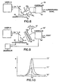
- An increased coding capacity can be obtained by allowing for more bits to be associated with each wavelength. This may be accomplished by considering the signal levels at each wavelength, as is indicated in Fig. 10 for a specific wavelength ⁇ 0 .
- the signal level may be directly controlled by the density of each of the coding emitters in each substrate. For example, three bits at a given ⁇ 0 can be created as:
- the information encoded at ⁇ 0 can be as follows:
- the teaching of this invention generally encompasses the use of security structures, which are considered to be a multi-component material, fibers, such as polymer filaments and textile threads, as well as planchettes, which may be disk-like round or polygonal bodies that are placed into the paper or other substrate, and which include a coating having the optical emitter.
- This invention thus teaches a security structure comprising a gain medium coupled to a structure that supports the creation of at least one mode for electromagnetic radiation.
- This invention further teaches a security structure comprising a gain medium coupled to a structure having a dimension or length in one or more directions for producing and supporting amplified spontaneous emission (ASE).
- ASE amplified spontaneous emission
- This invention further teaches a security device comprising an optical gain medium and a structure having boundaries that impart an overall geometry to the structure that, in combination with at least one material property of the structure, supports an enhancement of electromagnetic radiation emitted from the gain medium for favoring the creation of at least one mode that enhances an emission of electromagnetic radiation within a narrow band of wavelengths.
- Suitable, but not limiting, shapes for the structure comprise elongated, generally cylindrical shapes such as filaments, a sphere shape, a partial-sphere shape, a toroidal shape, a cubical and other polyhedral shape, and a disk shape.
- the structure is preferably comprised of at least one of a monolithic structure or a multi-layered structure or an ordered structure that may provide for distributed optical feedback.
- the security device forms a part of a currency, a passport, a lottery ticket, a negotiable security, a credit card or debit card, or any substrate or carrier which it is desired to at least one of authenticate, count, encode, sort or verify.
Abstract
Description
- This invention relates generally to optically-based methods and apparatus for performing sorting, coding and authentication of objects, such as paper or polymer based objects including currency, checks, negotiable instruments, passports, wills and other documents.
- In
U.S. Patent No. 5,448,582, issued September 5, 1995 , entitled "Optical Sources Having a Strongly Scattering Gain Medium Providing Laser-Like Action", the inventor disclosed a multi-phase gain medium including an emission phase (such as dye molecules) and a scattering phase (such as TiO2). A third, matrix phase may also be provided in some embodiments. Suitable materials for the matrix phase include solvents, glasses and polymers. The gain medium is shown to provide a laser-like spectral linewidth collapse above a certain pump pulse energy. The gain medium is disclosed to be suitable for encoding objects with multiple-wavelength codes, and to be suitable for use with a number of substrate materials, including polymers and textiles. - It is well known in the art to use various security techniques in an attempt to provide paper and other printable substrates that can be readily authenticated. Once the paper is authenticated, then the document or instrument printed on the paper may be assumed to be authentic as well, or at least to have passed a threshold test of authenticity. Watermarks, holograms, color changing inks and the like have all be used in the past. One well known technique places security threads in paper to hinder a non-authorized production of the paper or to authenticate already manufactured paper and/or a document or currency printed on the paper. Reference in this regard can be had to the following
U.S. Patents: 5, 486, 022 , "Security Threads Having At Least Two Security Detection Features and Security Papers Employing Same, by T.T. Crane;4,534,398 , "Security Paper", by T.T. Crane; and4,437,935 , "Method and Apparatus for Providing Security Features in Paper", by F.G. Crane, Jr. - In addition to the problem of authentication, other problems arise with the use of currency, documents, and other pliable substrates (e.g. textiles) such as when using automatic sorting and counting machines. In such applications the sorting and/or counting machine should be able to accurately distinguish between different denomination notes, while doing so in a real time environment where the notes are moving at a relatively high velocity.
- A problem also arises during a conventional use of fluorescent or phosphorescent materials. This problem is related to the saturation behavior of the optical output that is typical of these materials. Due to this saturation behavior the signal to noise properties of the output are degraded, especially for non-contact substrate processing.
-
WO 98/45803 - A very advantageous solution to the various problems discussed above would be to provide a security structure that could be incorporated into the matrix that forms the document, currency, negotiable instrument, etc., wherein the structure could function to both authenticate the substrate as well as to enhance the countability and/or sortability of the substrate. The security structure should be small so that it can incorporated into substrates, low cost, and exhibit non-saturating or substantially non-saturating behavior that provides the structure with a high signal to noise output and a capability of being used in a non-contact, high speed mode of operation. An optically-based security structure in accordance with the teachings of this invention would enable such a non-contact, high speed mode of operation.
- It is thus a first object and advantage of this invention to provide an improved optically based method and apparatus for authenticating objects, and possibly also counting and sorting objects, such as documents, currency, negotiable instruments, and other substrates that contain indicia.
- It is another object and advantage of this invention to provide an optically-based security structure that can be used in thin substrate materials, such as sheet-like substrate materials based on paper or polymer.
- It is a further object and advantage of this invention to provide a document or document substrate, such as paper or a polymer, that is printed and/or constructed so as enable the document or substrate to be accurately and unambiguously authenticated as being genuine, as well as to have enhanced counting and sorting properties.
- It is another object and advantage of this invention to provide a mode or amplified spontaneous emission (ASE) structure that allows for the circumvention of the conventional output saturation behavior that is typical of conventional fluorescent or phosphorescent materials, thereby greatly enhancing the signal to noise properties of the output from the substrate and allowing for highly improved and robust non-contact processing.
- It is one further object and advantage of this invention to provide an amplified spontaneous emission (ASE) structure in homogeneously or inhomogeneously broadened medium allowing for highly improved and robust non-contact processing of substrates, such as those that comprise currency and other documents.
- The foregoing and other problems are overcome and the objects and advantages of the invention are realized by methods and apparatus in accordance with embodiments of this invention.
- A first aspect of the invention is directed to a method for processing a document, comprising the steps of: providing a document to be authenticated, the document comprising: a substrate and at least one device that is comprised of an optical gain medium and a structure coupled to said gain medium for at least one of (a) favoring the creation of at least one mode that favors at least one narrow band of wavelengths over other wavelengths to enable energy in the at least one narrow band of wavelengths to constructively add or (b) supporting amplified spontaneous emission, said at least one device encoding information that is made manifest by an emission from said device; illuminating at least a portion of the document with light selected for exciting the gain medium; detecting an emission of at least one wavelength from the document in response to the step of illuminating; and obtaining the information that was encoded in the device from the detected emission, wherein more than two signal levels are associated with each wavelength of the at least one wavelength.
- A second aspect of the invention is directed to apparatus for at least one of authenticating, sorting or counting documents, comprising: a light source for illuminating all or a portion of a document, the document comprising: a substrate and at least one device located in or on said substrate, said device being comprised of an optical gain medium and a structure for at least one of (a) favoring the creation of at least one mode that favors at least one narrow band of wavelengths over other wavelengths to enable energy in the at least one narrow band of wavelengths to constructively add or (b) supporting amplified spontaneous emission for outputting light of at least one wavelength, said light source outputting light having wavelengths that are predetermined to excite said gain medium; at least one detector responsive to said wavelength for detecting the presence of the at least one wavelength; and decision logic, having an input coupled to an output of said at least one detector, for at least one of indicating the authenticity of the document based at least in part on a detection of the at least one wavelength, for counting the document based at least in part on a detection of the at least one wavelength or on the absence of the at least one wavelength, wherein more than two signal levels are associated with each wavelength of the at least one wavelength.
- A third aspect of the invention is directed to a security device for use with a substrate and comprising: a gain medium coupled to a structure for at least one of (a) favoring the creation of at least one mode that favors at least one narrow band of wavelengths over other wavelengths to enable energy in the at least one narrow band of wavelengths to constructively add or (b) supporting amplified spontaneous emission, wherein said structure is comprised of at least one of a monolithic structure, a multi-layered structure, or an ordered structure that provides distributed optical feedback for the creation of said at least one mode, wherein more than two signal levels are associated with each wavelength of the at least one wavelength.
- Disclosed herein are methods and apparatus for at least one of authenticating, sorting or counting documents, as well as security structures contained within documents. and documents containing security structures. The apparatus includes a laser or some other light source for illuminating all or a portion of a document. The document includes a substrate and at least one security structure or device located in or on the substrate.
- In accordance with the teachings of this invention the security structure includes, in one embodiment, a gain medium coupled to a structure that supports the creation of at least one mode for electromagnetic radiation.
- Further in accordance with the teachings of this invention the security structure includes, in another embodiment, a gain medium coupled to a structure having a dimension or length in one or more directions to produce and support amplified spontaneous emission (ASE).
- A security device in accordance with this invention has a structure with boundaries whose geometry and material properties (e.g., index of refraction) support an enhancement of electromagnetic radiation that may be emitted from a gain medium, such as a dye and/or semiconductor particles, that is also contained within the device. The structure may be provided so as to favor the creation of at least one mode so as to enhance electromagnetic radiation within a narrow band of wavelengths. Suitable shapes for the structure include, but are not limited to, elongated generally cylindrical shapes such as filaments, spheres, half-spheres, toroids, cubes and other polyhedral shapes, as well a disks. The structures may be monolithic structures or multi-layered structures, or a combination of same. Preferably the security devices containing the structures are of a size compatible with the dimensions of the substrate or carrier into which they are placed, such as paper or thin polymer sheets such as those used for credit cards, debit cards and identification cards, such as driver's licenses.
- A laser source may output light having wavelengths that are predetermined to excite the gain medium. Apparatus that comprises the laser further includes at least one photodetector, or an array of photodetectors, that is responsive to at least one predetermined wavelength, and decision logic for at least one of indicating the authenticity of a document containing the security device, for counting the document, or for sorting the document. The decision logic operates based at least in part on a detection of the at least one predetermined wavelength or on the absence of at least one predetermined wavelength. In addition, the decision process for authentication may include the linewidth and other spectral features of the signature, such as its derivative. These parameters may be employed to further corroborate the presence of a lasing emission signature.
- As employed herein a document could be a currency, or a passport, or a lottery ticket, or a negotiable security, or a credit card or a debit card, or an identification card such as a driver's license or employee's badge, or any substrate or carrier which it is desired to authenticate, count, encode with information, sort and/or verify.
- The above set forth and other features of the invention are made more apparent in the ensuing Detailed Description of the Invention when read in conjunction with the attached Drawings, wherein:
-
Fig. 1 illustrates a document having embedded fibers or threads that emit narrow-band light, when excited by an optical source such as a laser, containing one or more characteristic wavelengths; -
Fig. 2A illustrates a planchette embodiment of a security structure in accordance with the teachings of this invention; -
Fig. 2B illustrates a filament or fiber embodiment of a security structure in accordance with the teachings of this invention, and which is suitable for embodying the document threads shown inFig. 1 ; -
Fig. 2C illustrates a distributed feedback (DFB) embodiment of a security structure in accordance with the teachings of this invention; -
Fig. 2D illustrates a top view of a planchette, as inFig. 2A , or an end view of fiber, wherein the planchette or fiber is sectored and capable of outputting multiple wavelengths; -
Fig. 2E illustrates a top view of a planchette, as inFig. 2A , or an end view of fiber, wherein the planchette or fiber is radially structured so as to be capable of outputting multiple wavelengths; -
Fig. 3 is an enlarged, cross-sectional view of an embodiment of a security structure that is also suitable for embodying the document threads shown inFig. 1 ; -
Fig. 4 is an enlarged, cross-sectional view of an other embodiment of the security structure ofFig. 3 ; -
Fig. 5 depicts the emission peak of a selected dye in any of the embodiments ofFigs. 2A-2E , before (B) and after (A) a spectral collapse; -
Fig. 6 shows characteristic emission peaks for a thread comprised of a plurality of constituent polymeric fibers, each of which emits at a characteristic wavelength; -
Fig. 7 is a graph that illustrates a number of suitable dyes that can be used to form the gain medium in accordance with this invention; -
Fig. 8 is a simplified block diagram of a document authentication system that is an aspect of this invention; -
Fig. 9 is a simplified block diagram of a document sorting and counting system that is an aspect of this invention; and -
Fig. 10 depicts emission wavelength signal amplitude and is useful in explaining an embodiment of this invention wherein both wavelength and signal level amplitude coding are employed. - The disclosure of the above-referenced
U.S. Patent No. 5,448,582, issued September 5, 1995 , entitled "Optical Sources Having a Strongly Scattering Gain Medium Providing Laser-Like Action", by Nabil M. Lawandy is incorporated by reference herein in its entirety. Also incorporated by reference herein in its entirety is the disclosure ofU.S. Patent No. 5,434,878, issued July 18, 1995 , entitled "Optical Gain Medium Having Doped Nanocrystals of Semiconductors and also Optical Scatterers", by Nabil M. Lawandy. - This invention employs security structures that contain an optical gain medium that is capable of exhibiting laser-like activity (e.g., emission in a narrow band of wavelengths when excited by a source of excitation energy).
- However, unlike the structures disclosed in the above-referenced
U.S. Patent No.: 5,448,582 , the security structures in accordance with the teachings of this invention do not require the presence of a scattering phase or scattering sites to generate the narrow band of emissions. Instead, the optical gain medium that provides the amplified spontaneous emission in response to the illumination is responsive to, for example, size constraints, structural constraints, geometry constraints, and/or index of refraction mis-matches for emitting the narrow band of emissions. In other words, the size constraints, structural constraints, geometry constraints, and/or index of refraction mis-matches are used to provide for at least one mode in the security structure that favors at least one narrow band of wavelengths over other wavelengths, enabling emitted energy in the narrow band of wavelengths to constructively add. In another embodiment the size constraints, structural constraints, geometry constraints, and/or index of refraction mis-matches are used to provide for an occurrence of amplified spontaneous emission (ASE) in response to the step of illuminating. It should be noted that one may provide ASE within a mode, but that one does not require a mode to have ASE. In general, the ASE can occur in homogeneously and inhomogeneously broadened medium. - The security structure is thus comprised of a matrix phase, for example a polymer or solvent, that is substantially transparent at wavelengths of interest, and an electromagnetic radiation amplifying (gain) phase, for example a dye or a rare earth ion. The amplifying (gain) phase is placed within a structure, in accordance with the teachings of this invention, where the structure has a predetermined size, or structural features, or geometry, and/or an index of refraction that differs from the index of refraction of the substrate within which the security structure is intended for use. The structure tends to confine and possibly guide the electromagnetic radiation output from the amplifying (gain) phase, and may favor the creation of at least one mode, or the creation of amplified spontaneous emission (ASE). In either case the output may be contained in a narrow range of wavelengths, e.g., a few nanometers in width, and is considered herein as a narrowband emission. The matrix phase may comprise the material that forms the security structure, such as a polymeric planchette that contains the electromagnetic radiation amplifying (gain) phase.
- The invention is applied herein to the validation of the authenticity of documents, currency, checks, lottery tickets, and other similar instruments that are typically provided on paper or a paper-containing or paper-like substrate, as well as to automated methods and apparatus for counting and/or sorting such substrates. For the purposes of this invention a "security device" or "security structure" is intended to mean an object that is fabricated in accordance with this invention and which has dimensions suitable for being included within a desired substrate material, such as the paper of currency or a passport. Whether the object is intended for use in authenticating the substrates, or for counting the substrates, or for sorting the substrates, or for any combination of authentication, counting or sorting, the object is still referred to herein for convenience as a "security structure".
- The document or substrate containing the security structure or device could be, but is not limited to, a currency, or a passport, or a lottery ticket, or a negotiable security, or a credit card or a debit card, or an identification card, such as a driver's license or employee's badge, or any substrate or carrier which it is desired to authenticate, count, encode, sort and/or verify.
- This invention may also enable both public validation, e.g., by visual inspection, and machine-based validation, e.g., with the use of an optical source and one or more suitable optical detectors. Thus, two levels of authentication can be used.
-
Fig. 1 illustrates a first embodiment of this invention. A document, including any paper, paper-containing, orpolymer substrate 10, includes a plurality of embedded elongated bodies orthreads 12 that include a host material, such as a textile fiber or a polymer fiber, that is coated or impregnated with a dye or some other material capable of amplifying light. Thethreads 12 exhibit electro-optic properties consistent with laser action; i.e., an output emission that exhibits both a spectral linewidth collapse and a temporal collapse at an input pump energy above a threshold level. In response to illumination with laser light, such as frequency doubled light (i.e., 532 nm) from a Nd:YAG laser 14, thethreads 12 emit a wavelength λ that is characteristic of the chromic dye or other material that comprises the illuminatedthreads 12. A reflective coating can be applied so as to enhance the emission from thethreads 12. Anoptical detector 16, which may include a wavelength selective filter, can be used to detect the emission at the wavelength λ. The emission may also be detected visually, assuming that it lies within the visible portion of the spectrum. In either case, the detection of the emission at the characteristic wavelength λ indicates that the document is an authentic document, i.e., one printed on thesubstrate 10 having thethreads 12. It is assumed that only authentic documents are printed on such substrates, and that one wishing to fraudulently produce such a document would not have access to the substrate material. Currency is one specific example. -
Fig. 7 illustrates a number of exemplary dyes that are suitable for practicing this invention, and shows their relative energy output as a function of wavelength. The teaching of this invention is not limited for use with only the dyes listed inFig. 7 . -
Fig. 2A is an enlarged elevational view of a small disk-shaped security structure, also referred to as aplanchette 12A. Theplanchette 12A has, by example, a circular cylindrical shape with a diameter (D) and a thickness (T) that is less than the dimensions of the substrate material to which the planchette will be added. By example, U.S. currency has a thickness of about 100 microns, and D and T will both be significantly less than 100 microns. Also, and in accordance with this invention, T and nD, the perimeter, can be chosen to have values that are a function of a desired emission wavelength, such as one half wavelength or some multiple of one half wavelength. To this end theplanchette 12A is comprised of a polymer, or a glass, or some other suitable material, which contains an optical amplifying (gain) material, such as one of the dyes shown inFig. 7 . One surface of theplanchette 12A may be provided with a reflective coating. It is also preferred that the index of refraction (n) of theplanchette 12A be different from the index of refraction (n') of the desired substrate material (i.e., theplanchette 12A is non-index matched to the surrounding substrate.) - A planchette can also be designed so that ASE across the thickness T creates a narrowband emission, or such that ASE along an internal reflection path, such as the perimeter, leads to narrowband emission.
-
Fig. 2B depicts a fiber embodiment of the security structure, wherein the diameter (DM) offiber 12B is made to have a value that is a function of the desired emission wavelength, such as one half wavelength or some multiple of one half wavelength. As in the planchette embodiment ofFig. 2A , thefiber 12B is comprised of a polymer, or a glass, or some other suitable material, which contains an optical emitter, such as one of the dyes shown inFig. 7 . It is also again preferred that the index of refraction (n) of thefiber 12B be different from the index of refraction (n') of the desired substrate material so that thefiber 12B is non-index matched to the surrounding substrate. In this embodiment the electromagnetic radiation that is emitted by the dye is confined to the fiber and propagates therein. Due at least in part to the diameter of thefiber 12B one narrowband of wavelengths is preferred over other wavelengths, and energy in this band of wavelengths builds over time, relative to the other wavelengths. Preferably the diameter DM is made a function of the emission wavelength of the selected dye. The end result is a narrowband emission from thefiber 12B, when the dye contained in the matrix material of thefiber 12B is stimulated by an external laser source. -
Fig. 2C depicts a DFB embodiment of the security structure, wherein a periodic structure comprised of regions of first and second indices of refraction (n1 and n2) alternate along the length of theDFB structure 12C. Preferably n1 is not equal to n2, and neither are equal to n'. The thickness of each of the regions may be one quarter wavelength, or a multiple of one quarter wavelength, of the desired emission wavelength to provide a mode for the desired emission wavelength. -
Fig. 5 depicts the emission peak of the selected dye in any of the embodiments ofFigs. 2A-2E , before (B) and after (A) the spectral collapse made possible by the security structure having a predetermined size, or structural features, or geometry, and/or an index of refraction that differs from the index of refraction of the substrate within which the security structure is intended for use. - In general, and for the case of amplified spontaneous emission for high gain, homogeneously broadened media, the general expression is (for a cylinder-type geometry):

where g is the gain (e.g., 200cm-1), and L is a length that results in narrowband emission. The structure can include a propagating mode, and the mode can help guide the electromagnetic radiation, but the mode is not necessary for ASE to occur. For a dye, the gain g is approximately 200 cm-1, so for a ten fold linewidth collapse (Δλ/Δλ 0=0.1), L is approximately 2.5 mm. -
Fig. 2D illustrates a top view of aplanchette 12A, as inFig. 2A , or an end view offiber 12B, wherein the planchette or fiber is sectored (e.g., four sectors) and is capable of outputting multiple wavelengths (λ 1-λ 4).Fig. 2E illustrates a top view of aplanchette 12A, as inFig. 2A , or an end view offiber 12B, wherein the planchette or fiber is radially structured so as to be capable of outputting multiple wavelengths. Such multiple wavelength embodiments lend themselves to the wavelength encoding of information, as will be described in further detail below. -
Fig. 3 illustrates an embodiment of a structure wherein a one or more regions (e.g. three) 22, 24, 26 each include, by example, one or more dyes either alone or in combination with one or more rare earths that are selected for providing a desired wavelength λ 1, λ 2, λ 3. An underlying substrate, such as a thintransparent polymer layer 28, overlies areflective layer 30. Thereflective layer 30 can be a thin layer of metal foil, and may be corrugated or otherwise shaped or patterned as desired. The structure can be cut into thin strips which can be used to form thethreads 12 shown inFig. 1 . Under low level illumination provided by, for example, a UV lamp a public authentication can be provided based on a characteristic broad band fluorescent emission (e.g., some tens of nanometers or greater) of the dye and/or phosphor particles. However, when excited by thelaser 14 the structure emits a characteristic narrowband emission (e.g., less than about 10 nm) at each of the wavelengths λ 1, λ 2, λ 3. The presence of these three wavelengths can be detected with the detector ordetectors 16, in combination with suitable optical passband filters (see alsoFig. 8 ), thereby providing also a machine readable authentication of the document containing the structure. Alternatively, a spectrum analyzer (see alsoFig. 9 ) such as monolithic detector array with, by example, an optical wedge can be used to detect the spectrum. The output of the spectrum analyzer is then analyzed for detecting λ peaks and derivatives, and can be compared to a predetermined look-up table. - If desired, a
suitable coating 32 can be applied to theregions coating 32 can provide UV stability and/or protection from abrasive forces. A thin transparent UV absorbing polymer coating is one suitable example, as are dyes, pigments and phosphors. - For the case where the
coating 32 is applied, the coating can be selected to be or contain a fluorescent material. In this case thecoating 32 can be excited with a UV source to provide the public authentication function. - The
threads 12 may be comprised of fibers such as nylon-6, nylon 6/6, PET, ABS, SAN, and PPS. By example, a selected dye may be selected from Pyrromethene 567,Rhodamine 590 chloride, andRhodamine 640 perchlorate. The selected dye may be compounded with a selected polymer resin and then extruded. Wet spinning is another suitable technique for forming the fibers. A suitable dye concentration is 2 X 10⁻³ M. Extrusion at 250°C followed by cooling in a water bath is one suitable technique for forming thefibers 12. When used in a paper substrate the diameter is sized accordingly, and in accordance with the selected emission wavelength. A suitable excitation (pump 12) fluence is in the range about 5 mJ/cm2 and greater. Two or more fibers, each containing a different dye, can be braided together or otherwise connected to provide a composite fiber that exhibits emission at two or more wavelengths. Alternatively, the sectored embodiment ofFig. 2D can be employed, or the radial embodiment ofFig. 2E . It should be realized that simply slicing fibers so constructed can be used to create theplanchettes 12A. - By example,
Fig. 6 illustrates the emission from a braided pair of nylon fibers, excited at the 532 nm line of a frequency doubled Nd:YAG laser 12, containing 2 X 10⁻³ M Pyrromethene 567 andRhodamine 640 perchlorate with emission peaks at 552 nm and 615 nm, respectively. By varying the dye-doped fiber types in various combinations of braided or otherwise combined fibers, the resulting composite fibers orthreads 12 make it possible to optically encode information into the paper or other host material. By example, currency can be encoded with its denomination by the selection of thread emission wavelength(s). For example, $100 notes would emit with a first characteristic optical signature, while $50 notes would emit with a second characteristic optical signature. The characteristic emission lines may be more narrowly spaced than shown inFig. 6 . By example, in that the emission lines of individual ones of the fibers are of the order of 4 nm, one or more further emission wavelengths can be spaced apart at about 6 nm intervals. - The dye can also be incorporated by a dyeing process of polymers with active sites and specifically designed dyes that bind to the active sites.
- It is also within the scope of the invention to provide a single fiber with two dyes, where the emission from one dye is used to excite the other dye, and wherein only the emission from the second dye may be visible.
- In one
embodiment Rhodamine 640 is excited at 532 nm. TheRhodamine 640 emits 620 nm radiation with is absorbed by Nile Blue, which in turn emits at 700 nm. -
Fig. 4 illustrates an embodiment wherein thepolymer substrate 28 ofFig. 3 is removed, and theregions material reflector layer 30. In this embodiment it can be appreciated that a thickness modulation of the gain medium regions occurs, enabling multiple wavelengths to be produced if multiple dyes are included. -
Fig. 8 illustrates an embodiment of a suitable apparatus for authenticating a document in accordance with one aspect of this invention. Theauthentication system 50 includes thelaser 14, such as but not limited to a frequency doubled Nd:YAG laser, that has apulsed output beam 14a.Beam 14a is directed to a mirror M and thence to thedocument 10 to be authenticated. Thedocument 10, which could be currency, is disposed on asupport 52. One or both of the mirror M andsupport 52 may be capable of movement, enabling thebeam 12a to be scanned over thedocument 10. Assuming that thedocument 10 includes thethreads 12, and/or theplanchettes 12A, or any of the other disclosed embodiments of security structures, one or more emission wavelengths (e.g., λ1 to λn) are generated. A suitable passband filter F can be provided for each emission wavelength of interest (e.g., F1 to Fn). The output of each filter F1-Fn is optically coupled through free space or through an optical fiber to a corresponding photodetector PD1 to PDn. The electrical outputs of PD1 to PDn are connected to acontroller 54 having anoutput 54a for indicating whether thedocument 10 is authentic. Thedocument 10 is declared to be authentic only when all of the expected emission wavelengths are found to be present, i.e., only when PD1 to PDn each output an electrical signal that exceeds some predetermined threshold. A further consideration can be an expected intensity of the detected wavelength(s) and/or a ratio of intensities of individual wavelengths one to another. - It should be realized that the
support 52 could be a conveyor belt that conveys documents past the stationary or scannedbeam 12a. It should further be realized that a prism, wedge or grating could replace the individual filters F1-Fn, in which case the photodetectors PD1-PDn are spatially located so as to intercept the specific wavelength outputs of the prism or grating. The photodetectors PD1-PDn could also be replaced by one or more area imaging arrays, such as a silicon or CCD imaging array, as is shown inFig. 9 . In this case it is expected that the array will be illuminated at certain predetermined pixel locations if all of the expected emission wavelengths are present. It is assumed that the photodetector(s) or imaging array(s) exhibit a suitable electrical response to the wavelength or wavelengths of interest. However, and as was noted above, it is possible to closely space the emission wavelengths (e.g., the emission wavelengths can be spaced about 6 nm apart). This enables a plurality of emission wavelengths to be located within the maximum responsivity wavelength range of the selected detector(s) . - The
controller 54 can be connected to thelaser 14, mirror M,support 52, and other system components, such as a rotatable wedge that replaces the fixed filters F1-Fn, for controlling the operation of these various system components. -
Fig. 9 is a simplified block diagram of a document sorting and counting system 50' that is a further aspect of this invention. The apparatus ofFig. 9 can be similar to that ofFig. 8 , however, the controller 54' outputs aCount signal 54a' and may also provide a signal to adiverter mechanism 56 for directing the document being examined to a predetermined destination. In this embodiment it is assumed that thesupport 52 is a conveyor belt or some similar apparatus that conveys documents past the stationary or scannedbeam 12a. If only a counting function is used then a minimum of one wavelength (and hence one photodetector) need be employed, assuming that only one type of document is to be counted. One wavelength could also be employed in the sorting case, if it were assumed that a desired document emits a predetermined wavelength while other documents do not emit at all, or emit at a different wavelength. In this case thediverter mechanism 56 may be activated either if the expected emission is present or is not present. -
Fig. 9 also shows the case where the discrete photodetectors ofFig. 8 are replaced by amonolithic area array 53 comprised ofpixels 53a. Thearray 53, in combination with some type of device for spatially distributing the output spectrum over the array, such as awedge 55, provides a spectrum analyzer in combination with controller 54'. That is, the spectrum (SP) emanating from thedocument 10 is detected and converted to an electrical signal for analysis by software in the controller 54'. By example, the peaks in the spectrum are identified and are associated with particular wavelengths by their locations on thearray 53. Information that is conveyed by the wavelength peaks (and/or some other spectral feature, such as the peak width, or peak spacing, or the derivative) is then used to authenticate thedocument 10, or to detect a type of document or to ascertain some other information about the document, and/or to count and/or sort the document. - It should be realized that the embodiments of
Figs. 8 and 9 could be combined into one apparatus that authenticates, counts and sorts documents, such as currency or financial instruments. - Further in accordance with the teachings of this invention the coding of various substrates can be accomplished by a strictly binary wavelength domain code, or by an approach that also includes the amplitude of the signals.
- In the binary scheme the substrates may be impregnated with combinations of N lasing wavelengths out of a total palette of M lasing wavelengths. The presence of a signal at a specific wavelength denotes a "1" while its absence denotes a "0". If M wavelength choices are available, for example in the form of
fibers 12B orplanchettes 12A, then there exist a total of 2M-1 possible codes. For example, M=3 different wavelength fibers can create seven different codes. This approach can, for example, be used to code the existing denominations of U.S. currency. - Furthermore, if only N wavelengths at a time are incorporated in any given substrate, then there exist

possibilities, where ! indicates factorial. For example, with M=5 different laser wavelengths to choose from one has:
(1 fiber in each substrate) = 5 
(2 fibers in each substrate) = 10 
(3 fibers in each substrate) = 10 
(4 fibers in each substrate) = 5 
(all 5 fibers in a substrate) = 1 - An increased coding capacity can be obtained by allowing for more bits to be associated with each wavelength. This may be accomplished by considering the signal levels at each wavelength, as is indicated in
Fig. 10 for a specific wavelength λ 0. The signal level may be directly controlled by the density of each of the coding emitters in each substrate. For example, three bits at a given λ 0 can be created as: - "0", no emission at λ 0
- "1", emission at a signal strength = A
- "2", emission at a signal strength = B>A, where A is a chosen signal level corresponding a given loading of the lasing emitter.
- Further by example, the information encoded at λ 0 can be as follows:
- "0", no emission at λ 0
- "+1", emission at a signal strength = A
- "-1", emission at a signal strength = B>A.
- Using an exemplary trinary scheme as described, M different wavelengths can create 3N-1 discrete codes. If Y discrete amplitude levels are chosen, then there are YN-1 choices. In an exemplary multi-level coding scheme, for M=3, Y=3, a total of 26 codes are provided, as opposed to seven in the strictly binary case.
- The teaching of this invention generally encompasses the use of security structures, which are considered to be a multi-component material, fibers, such as polymer filaments and textile threads, as well as planchettes, which may be disk-like round or polygonal bodies that are placed into the paper or other substrate, and which include a coating having the optical emitter.
- This invention thus teaches a security structure comprising a gain medium coupled to a structure that supports the creation of at least one mode for electromagnetic radiation.
- This invention further teaches a security structure comprising a gain medium coupled to a structure having a dimension or length in one or more directions for producing and supporting amplified spontaneous emission (ASE).
- This invention further teaches a security device comprising an optical gain medium and a structure having boundaries that impart an overall geometry to the structure that, in combination with at least one material property of the structure, supports an enhancement of electromagnetic radiation emitted from the gain medium for favoring the creation of at least one mode that enhances an emission of electromagnetic radiation within a narrow band of wavelengths. Suitable, but not limiting, shapes for the structure comprise elongated, generally cylindrical shapes such as filaments, a sphere shape, a partial-sphere shape, a toroidal shape, a cubical and other polyhedral shape, and a disk shape. The structure is preferably comprised of at least one of a monolithic structure or a multi-layered structure or an ordered structure that may provide for distributed optical feedback. In a preferred embodiment of this invention the security device forms a part of a currency, a passport, a lottery ticket, a negotiable security, a credit card or debit card, or any substrate or carrier which it is desired to at least one of authenticate, count, encode, sort or verify.
Claims (20)
- A method for processing a document, comprising the steps of:providing a document (10) to be authenticated, the document comprising:a substrate (10) and at least one device (12) that is comprised of an optical gain medium and a structure coupled to said gain medium for at least one of (a) favoring the creation of at least one mode that favors at least one narrow band of wavelengths over other wavelengths to enable energy in the at least one narrow band of wavelengths to constructively add or (b) supporting amplified spontaneous emission, said at least one device encoding information that is made manifest by an emission from said device;illuminating at least a portion of the document with light (14a) selected for exciting the gain medium;detecting an emission of at least one wavelength (λ1, λn) from the document in response to the step of illuminating; andobtaining the information that was encoded in the device from the detected emission,wherein more than two signal levels are associated with each wavelength of the at least one wavelength.
- A method as in claim 1, and further comprising a step of declaring the document to be authentic only if the emission is detected and confirmed to be a laser-like emission.
- A method as in claim 1, and further comprising a step of directing further processing of the document based on the obtained information.
- A method as in claim 1, wherein the signal levels correspond to bit information.
- A method as in claim 1, wherein the information is encoded using both wavelength encoding and signal level encoding.
- The method of claim 1, wherein the more than two signal levels include a no emission level, a first emission level corresponding to a predetermined loading of the at least one device, and a second emission level corresponding to a level greater than the first emission level.
- Apparatus (50) for at least one of authenticating, sorting or counting documents, comprising:a light source (14) for illuminating all or a portion of a document (10), the document comprising:a substrate (10) and at least one device (12) located in or on said substrate, said device being comprised of an optical gain medium and a structure for at least one of (a) favoring the creation of at least one mode that favors at least one narrow band of wavelengths over other wavelengths to enable energy in the at least one narrow band of wavelengths to constructively add or (b) supporting amplified spontaneous emission for outputting light of at least one wavelength,said light source outputting light (14a) having wavelengths that are predetermined to excite said gain medium;at least one detector (PD; 53) responsive to said wavelength for detecting the presence of the at least one wavelength; anddecision logic (54), having an input coupled to an output of said at least one detector, for at least one of indicating the authenticity of the document based at least in part on a detection of the at least one wavelength, for counting the document based at least in part on a detection of the at least one wavelength or on the absence of the at least one wavelength,wherein more than two signal levels are associated with each wavelength of the at least one wavelength.
- The apparatus of claim 7, wherein the structure supports amplified spontaneous emission through at least one of the group consisting of size constraints, structural constraints, geometry constraints, and index of refraction mismatches between the structure and the substrate.
- The apparatus of claim 7, wherein the structure supports amplified spontaneous emission through index of refraction mismatches between the structure and the substrate.
- The apparatus of claim 7, wherein the at least one device is a security structure, wherein the security structure is comprised of one of the group consisting of 1) at least one filament (12B), and wherein the emitted wavelength is a function of a diameter of the filament, 2) a planchette (12A), and wherein the emitted wavelength is a function of the thickness of the planchette, and 3) a DFB structure (12C) comprised of alternating regions, and wherein the emitted wavelength is a function of the thickness of individual ones of the regions.
- The apparatus of claim 7, wherein the more than two signal levels include a no emission level, a first emission level corresponding to a predetermined loading of the at least one device located in or on said substrate, and a second emission level corresponding to a level greater than the first emission level.
- The apparatus of claim 7, wherein said detector is comprised of a plurality of discrete photodetectors (PD1, PDn).
- The apparatus of claim 7, wherein said detector is comprised of an area array (53).
- The apparatus of claim 7, wherein said detector is comprised of a spectrum analyzer.
- The apparatus of claim 7, wherein said device emits a single wavelength.
- The apparatus of claim 7, wherein said device emits a plurality of wavelengths.
- A security device for use with a substrate and comprising:a gain medium coupled to a structure for at least one of (a) favoring the creation of at least one mode that favors at least one narrow band of wavelengths over other wavelengths to enable energy in the at least one narrow band of wavelengths to constructively add or (b) supporting amplified spontaneous emission, wherein said structure is comprised of at least one of a monolithic structure, a multi-layered structure, or an ordered structure that provides distributed optical feedback for the creation of said at least one mode, wherein more than two signal levels are associated with each wavelength of the at least one wavelength.
- The security device of claim 17, wherein suitable shapes for said structure comprise elongated, generally cylindrical shapes such as filaments, a spherical shape, a partial-spherical shape, a toroidal shape, a cubical and other polyhedral shape, and a disk shape.
- The security device of claim 17, wherein said structure is comprised of at least one of a monolithic structure or a multi-layered structure or an ordered structure that may provide for distributed optical feedback for the creation of a mode.
- A security device as in claim 17, wherein said security device is a part of a currency, a passport, a lottery ticket, a negotiable security, a credit card or debit card, an identification card, or any substrate or carrier which it is desired to at least one of authenticate, count, encode, sort or verify.
Priority Applications (1)
| Application Number | Priority Date | Filing Date | Title |
|---|---|---|---|
| CY20111100393T CY1111395T1 (en) | 1999-02-08 | 2011-04-18 | OPTICAL METHODS AND APPLIANCES FOR CLASSIFICATION, CODESCRIPTION AND CERTIFICATION USING MEDIUM-TERMINAL EMISSION |
Applications Claiming Priority (3)
| Application Number | Priority Date | Filing Date | Title |
|---|---|---|---|
| US246818 | 1981-03-23 | ||
| US09/246,818 US6552290B1 (en) | 1999-02-08 | 1999-02-08 | Optically-based methods and apparatus for performing sorting coding and authentication using a gain medium that provides a narrowband emission |
| PCT/US2000/000412 WO2000046742A1 (en) | 1999-02-08 | 2000-01-07 | Optically-based methods and apparatus for sorting, coding, and authentication using a narrowband emission gain medium |
Publications (3)
| Publication Number | Publication Date |
|---|---|
| EP1222616A1 EP1222616A1 (en) | 2002-07-17 |
| EP1222616A4 EP1222616A4 (en) | 2005-07-06 |
| EP1222616B1 true EP1222616B1 (en) | 2011-03-16 |
Family
ID=22932352
Family Applications (1)
| Application Number | Title | Priority Date | Filing Date |
|---|---|---|---|
| EP00902359A Expired - Lifetime EP1222616B1 (en) | 1999-02-08 | 2000-01-07 | Optically-based methods and apparatus for sorting, coding, and authentication using a narrowband emission gain medium |
Country Status (18)
| Country | Link |
|---|---|
| US (2) | US6552290B1 (en) |
| EP (1) | EP1222616B1 (en) |
| JP (2) | JP2002536214A (en) |
| KR (1) | KR20010101808A (en) |
| CN (1) | CN1351731A (en) |
| AT (1) | ATE502352T1 (en) |
| AU (1) | AU770214B2 (en) |
| BR (1) | BR0008085A (en) |
| CA (1) | CA2361417C (en) |
| CY (1) | CY1111395T1 (en) |
| DE (2) | DE60045741D1 (en) |
| DK (1) | DK1222616T3 (en) |
| ES (1) | ES2360033T3 (en) |
| IL (1) | IL144791A0 (en) |
| MX (1) | MXPA01008040A (en) |
| PT (1) | PT1222616E (en) |
| WO (1) | WO2000046742A1 (en) |
| ZA (1) | ZA200106400B (en) |
Families Citing this family (59)
| Publication number | Priority date | Publication date | Assignee | Title |
|---|---|---|---|---|
| US6552290B1 (en) * | 1999-02-08 | 2003-04-22 | Spectra Systems Corporation | Optically-based methods and apparatus for performing sorting coding and authentication using a gain medium that provides a narrowband emission |
| US6996252B2 (en) * | 2000-04-19 | 2006-02-07 | Digimarc Corporation | Low visibility watermark using time decay fluorescence |
| FR2813134B1 (en) * | 2000-08-21 | 2004-01-16 | Banque De France | METHOD FOR AUTHENTICATING SENSITIVE DOCUMENTS |
| US7028188B1 (en) | 2000-10-30 | 2006-04-11 | Hewlett-Packard Development Company, L.P. | Document authentication using the physical characteristics of underlying physical media |
| DE50213638D1 (en) * | 2001-07-12 | 2009-08-06 | Uster Technologies Ag | METHOD FOR DETECTING FOREIGN MATERIALS IN A TEXTILE MATERIAL |
| US7213757B2 (en) | 2001-08-31 | 2007-05-08 | Digimarc Corporation | Emerging security features for identification documents |
| DE10156852A1 (en) * | 2001-11-20 | 2003-05-28 | Giesecke & Devrient Gmbh | Object, especially valuable and security document has security marker with emitter layer for stimulated optical emission and periodic modulation, especially height modulation |
| US7134959B2 (en) * | 2003-06-25 | 2006-11-14 | Scientific Games Royalty Corporation | Methods and apparatus for providing a lottery game |
| US8796030B2 (en) * | 2003-07-12 | 2014-08-05 | Parallel Synthesis Technologies, Inc. | Methods for optically encoding an object with upconverting materials and compositions used therein |
| US7252222B2 (en) * | 2003-12-19 | 2007-08-07 | Scientific Game Royalty Corporation | Embedded optical signatures in documents |
| US7364091B2 (en) * | 2003-12-19 | 2008-04-29 | Scientific Games International, Inc. | Embedded optical signatures in documents |
| FR2866460B1 (en) * | 2004-02-13 | 2008-11-07 | Banque De France | DOCUMENT SECURING METHOD, ASSOCIATED MACHINE AND AUTHENTICATION METHOD |
| EP1751240B2 (en) * | 2004-04-01 | 2020-03-18 | Sun Chemical Corporation | Photoinitiators for use in intaglio printing inks |
| US7788482B2 (en) * | 2004-05-10 | 2010-08-31 | Scientific Games International, Inc. | System and method for securing on-line documents using authentication codes |
| US8037307B2 (en) * | 2004-05-10 | 2011-10-11 | Scientific Games International Inc. | System and method for securing on-line documents using authentication codes |
| US7621814B2 (en) * | 2004-07-22 | 2009-11-24 | Scientific Games International, Inc. | Media enhanced gaming system |
| US7326871B2 (en) * | 2004-08-18 | 2008-02-05 | Mss, Inc. | Sorting system using narrow-band electromagnetic radiation |
| DE102004043064A1 (en) * | 2004-09-06 | 2006-03-09 | Giesecke & Devrient Gmbh | Security element with machine-readable authenticity feature |
| US7631871B2 (en) * | 2004-10-11 | 2009-12-15 | Scientific Games International, Inc. | Lottery game based on combining player selections with lottery draws to select objects from a third set of indicia |
| US8927892B2 (en) * | 2004-10-22 | 2015-01-06 | Parallel Synthesis Technologies | Rare earth downconverting phosphor compositions for optically encoding objects and methods and apparatus relating to same |
| US20060217181A1 (en) * | 2004-10-28 | 2006-09-28 | Chantal Jubinville | On-line lottery extension game having an instant component and a draw-based component |
| WO2006049934A2 (en) * | 2004-10-28 | 2006-05-11 | Scientific Games Royalty Corporation | Lottery game played on a geometric figure using indicia with variable point values |
| US7213811B2 (en) * | 2004-12-08 | 2007-05-08 | Scientific Games Royalty Corporation | Extension to a lottery game for which winning indicia are set by selections made by winners of a base lottery game |
| US7662038B2 (en) * | 2005-01-07 | 2010-02-16 | Scientific Games International, Inc. | Multi-matrix lottery |
| EP1861184A4 (en) * | 2005-01-07 | 2009-05-13 | Scient Games Int Inc | Lottery game utilizing nostalgic game themes |
| CN101163527A (en) * | 2005-01-11 | 2008-04-16 | 科学游戏程序国际有限公司 | On-line lottery game in which supplemental lottery-selected indicia are available for purchase |
| US20060170951A1 (en) * | 2005-01-31 | 2006-08-03 | Hewlett-Packard Development Company, L.P. | Method and arrangement for inhibiting counterfeit printing of legal tender |
| US7481431B2 (en) * | 2005-02-01 | 2009-01-27 | Scientific Games International, Inc. | Bingo-style lottery game ticket |
| US8262453B2 (en) * | 2005-02-09 | 2012-09-11 | Scientific Games International, Inc. | Combination lottery and raffle game |
| US7874902B2 (en) | 2005-03-23 | 2011-01-25 | Scientific Games International. Inc. | Computer-implemented simulated card game |
| EP1874418A1 (en) * | 2005-04-27 | 2008-01-09 | Scientific Games International, Inc. | Game apparatus |
| US7654529B2 (en) | 2005-05-17 | 2010-02-02 | Scientific Games International, Inc. | Combination scratch ticket and on-line game ticket |
| DE102005041054A1 (en) * | 2005-08-30 | 2007-03-01 | Giesecke & Devrient Gmbh | Bank notes e.g. US-notes, originality verification method, involves providing material as authenticity feature activated for emission of luminance radiation, to bank notes, and detecting emitted radiation in specific wavelength range |
| US8673107B2 (en) * | 2005-10-28 | 2014-03-18 | Parallel Synthesis Technologies | Methods for fabricating optically encoded particles and methods for optically encoding objects with such particles |
| US7369917B2 (en) * | 2006-01-17 | 2008-05-06 | National Instruments Corporation | System and method for automatic sorting of elements in drawing specifications for efficient tracing using motion control |
| US20080042424A1 (en) * | 2006-08-04 | 2008-02-21 | Pitney Bowes Incorporated | Postage stamps having values thereof luminescently encoded thereon and methods of reading such stamps |
| US7820009B2 (en) * | 2006-08-18 | 2010-10-26 | The Royal Institution For The Advancement Of Learning/Mcgill University | Cellulose composites comprising hydrophobic particles and their use in paper products |
| DE102006043119A1 (en) * | 2006-09-08 | 2008-03-27 | Bundesdruckerei Gmbh | Security and / or value document with a type II semiconductor contact system |
| WO2009145813A1 (en) | 2008-03-04 | 2009-12-03 | Qd Vision, Inc. | Particles including nanoparticles, uses thereof, and methods |
| WO2010028085A2 (en) * | 2008-09-03 | 2010-03-11 | The Regents Of The University Of California | Surgical object tracking system |
| US8137811B2 (en) * | 2008-09-08 | 2012-03-20 | Intellectual Product Protection, Llc | Multicomponent taggant fibers and method |
| US9782995B2 (en) | 2009-02-17 | 2017-10-10 | Malte Pflughoefft | Security and/or value document having a type II semiconductor contact system |
| US10173454B2 (en) | 2009-02-17 | 2019-01-08 | Bundesdruckerei Gmbh | Security and/or value document having a type II semiconductor contact system |
| US20100264371A1 (en) * | 2009-03-19 | 2010-10-21 | Nick Robert J | Composition including quantum dots, uses of the foregoing, and methods |
| WO2011031876A1 (en) | 2009-09-09 | 2011-03-17 | Qd Vision, Inc. | Formulations including nanoparticles |
| KR101865888B1 (en) | 2009-09-09 | 2018-06-08 | 삼성전자주식회사 | Particles including nanoparticles, uses thereof, and methods |
| US8808080B2 (en) | 2010-05-14 | 2014-08-19 | Scientific Games International, Inc. | Grid-based lottery game and associated method |
| US8460081B2 (en) | 2010-05-14 | 2013-06-11 | Scientific Games International, Inc. | Grid-based multi-lottery game and associated method |
| US9239262B2 (en) * | 2011-07-15 | 2016-01-19 | Honeywell International Inc. | Methods and apparatus for authenticating articles with luminescent phosphor compounds |
| EP2888392B1 (en) | 2012-08-23 | 2017-10-11 | The Regents of The University of California | Spectrally encoded microbeads and methods and devices for making and using same |
| DE102012110531A1 (en) | 2012-11-05 | 2014-05-08 | Infineon Technologies Ag | Chip card arrangement, chip card, apparatus for contactless interaction with a chip card arrangement or a chip card and method for operating and method for producing a chip card arrangement or chip card |
| US9741515B1 (en) * | 2013-02-19 | 2017-08-22 | Amazon Technologies, Inc. | Structures for representation of an operational state |
| US9878574B2 (en) | 2015-08-11 | 2018-01-30 | YPB Group, Ltd. | Security foil and method |
| US10254136B1 (en) * | 2016-04-18 | 2019-04-09 | Rockwell Collins, Inc. | Prismatic relative positioning system |
| US11747268B2 (en) | 2017-03-01 | 2023-09-05 | Spectra Systems Corporation | Coded polymer substrates for banknote authentication |
| GB201711097D0 (en) | 2017-07-10 | 2017-08-23 | Univ Court Univ St Andrews | Laser device |
| EP3721601A4 (en) * | 2017-12-08 | 2021-08-25 | Spectra Systems Corporation | Taggant system |
| CN108672318B (en) * | 2018-04-17 | 2020-06-16 | 江苏理工学院 | Appearance detection device based on machine vision |
| US11398870B2 (en) * | 2020-03-13 | 2022-07-26 | General Electric Company | Systems and methods for optical data communication using wide bandgap semiconductor detectors |
Family Cites Families (43)
| Publication number | Priority date | Publication date | Assignee | Title |
|---|---|---|---|---|
| US3068063A (en) | 1962-12-11 | Cellulose acetate spinning solutions | ||
| GB417488A (en) | 1933-11-25 | 1934-10-05 | Waterlow & Sons Ltd | Improved means for establishing the authenticity of bank notes, bonds, or like documents |
| US2208653A (en) | 1937-09-16 | 1940-07-23 | Celanese Corp | Safety paper |
| US2255696A (en) | 1938-04-05 | 1941-09-09 | Waterlow & Sons Ltd | Means for safeguarding bank notes, bonds, and like documents of value from fraudulent imitation |
| CH516196A (en) | 1965-03-08 | 1971-11-30 | American Cyanamid Co | Method of retrieving recorded information |
| DE2037755C3 (en) | 1970-07-30 | 1979-08-30 | National Rejectors Inc. Gmbh, 2150 Buxtehude | Device for checking notes of value |
| US3760292A (en) * | 1970-12-22 | 1973-09-18 | Bell Telephone Labor Inc | Integrated feedback laser |
| DE2925273C2 (en) * | 1979-06-22 | 1981-09-17 | GAO Gesellschaft für Automation und Organisation mbH, 8000 München | Security with a security thread |
| EP0052624B1 (en) | 1980-05-30 | 1985-01-30 | GAO Gesellschaft für Automation und Organisation mbH | Paper securities with authenticity mark of luminescent material |
| ES503112A0 (en) | 1980-05-30 | 1982-04-01 | Gao Ges Automation Org | IMPROVEMENTS IN THE MANUFACTURE OF CURRENCY AND SIMI-LARES PAPER |
| ES503245A0 (en) | 1980-05-30 | 1982-05-16 | Gao Ges Automation Org | IMPROVEMENTS IN THE MANUFACTURE OF PAPER FOR BANK AND SIMILAR BANKNOTES |
| CH653459A5 (en) * | 1981-04-16 | 1985-12-31 | Landis & Gyr Ag | DOCUMENT WITH A SECURITY THREAD AND METHOD for currency authentication SAME. |
| US4437935A (en) | 1981-06-03 | 1984-03-20 | Crane And Company | Method and apparatus for providing security features in paper |
| DE3122470C2 (en) | 1981-06-05 | 1985-09-05 | GAO Gesellschaft für Automation und Organisation mbH, 8000 München | Security paper and process for making the same |
| US5026141A (en) * | 1981-08-24 | 1991-06-25 | G2 Systems Corporation | Structural monitoring system using fiber optics |
| JPS58181000A (en) * | 1982-04-19 | 1983-10-22 | 株式会社日立製作所 | Same phase light super radiation emission device |
| US4534398A (en) | 1984-04-30 | 1985-08-13 | Crane & Co. | Security paper |
| FR2583794B1 (en) * | 1985-06-24 | 1988-09-23 | Arjomari Prioux | SAFETY DOCUMENT USING OPTICAL FIBERS, MANUFACTURING METHOD AND AUTHENTICATION METHOD. |
| US4678322A (en) | 1986-05-30 | 1987-07-07 | Xerox Corporation | Method and apparatus for the prevention of unauthorized copying of documents |
| US4738901A (en) | 1986-05-30 | 1988-04-19 | Xerox Corporation | Method and apparatus for the prevention of unauthorized copying of documents |
| GB8828091D0 (en) | 1988-12-01 | 1989-01-05 | Traqson Ltd | Security marking |
| DE69004571T2 (en) * | 1989-06-22 | 1994-03-10 | British Telecomm | OPTICAL REFLECTION MEASUREMENT IN THE TIME AREA. |
| US5093147A (en) | 1990-09-12 | 1992-03-03 | Battelle Memorial Institute | Providing intelligible markings |
| DE4114732A1 (en) | 1991-05-06 | 1992-11-12 | Helmut Dr Bayer | Banknote security mark - uses 2 or more substances which are fluorescent under ultraviolet of different wavelengths |
| US5291267A (en) * | 1992-01-22 | 1994-03-01 | Hewlett-Packard Company | Optical low-coherence reflectometry using optical amplification |
| JPH05327109A (en) * | 1992-03-26 | 1993-12-10 | Idemitsu Kosan Co Ltd | Organic optical gain element and its excitation method |
| US5434878A (en) | 1994-03-18 | 1995-07-18 | Brown University Research Foundation | Optical gain medium having doped nanocrystals of semiconductors and also optical scatterers |
| US5448582A (en) | 1994-03-18 | 1995-09-05 | Brown University Research Foundation | Optical sources having a strongly scattering gain medium providing laser-like action |
| US5881886A (en) * | 1994-03-18 | 1999-03-16 | Brown University Research Foundation | Optically-based methods and apparatus for sorting garments and other textiles |
| US6100973A (en) * | 1994-03-18 | 2000-08-08 | Spectra Science Corporation | Methods and apparatus for performing microanalytical techniques using photolithographically fabricated substrates having narrow band optical emission capability |
| US5903340A (en) * | 1994-03-18 | 1999-05-11 | Brown University Research Foundation | Optically-based methods and apparatus for performing document authentication |
| US5486022A (en) | 1994-04-04 | 1996-01-23 | Crane & Co., Inc. | Security threads having at least two security detection features and security papers employing same |
| US6259506B1 (en) * | 1997-02-18 | 2001-07-10 | Spectra Science Corporation | Field activated security articles including polymer dispersed liquid crystals, and including micro-encapsulated field affected materials |
| DE19758587C2 (en) | 1997-03-04 | 2003-03-27 | Bundesdruckerei Gmbh | Arrangement for the visual and mechanical authenticity check of value and security documents |
| US6047964A (en) * | 1997-04-18 | 2000-04-11 | Spectra Science Corporation | Scratch card, and method and apparatus for validation of the same |
| US6064476A (en) * | 1998-11-23 | 2000-05-16 | Spectra Science Corporation | Self-targeting reader system for remote identification |
| CA2311465A1 (en) * | 1997-11-25 | 1999-06-03 | William Goltsos | Self-targeting reader system for remote identification |
| US6744525B2 (en) * | 1997-11-25 | 2004-06-01 | Spectra Systems Corporation | Optically-based system for processing banknotes based on security feature emissions |
| PL346343A1 (en) * | 1998-05-13 | 2002-02-11 | Spectra Science Corp | Micro-lasing beads and structures, and associated methods |
| DE19836813A1 (en) | 1998-08-14 | 2000-02-24 | Bundesdruckerei Gmbh | Value and security document with optically stimulable dyes for authenticity testing |
| US6296189B1 (en) * | 1998-08-26 | 2001-10-02 | Spectra Science Corporation. | Methods and apparatus employing multi-spectral imaging for the remote identification and sorting of objects |
| US6692031B2 (en) * | 1998-12-31 | 2004-02-17 | Mcgrew Stephen P. | Quantum dot security device and method |
| US6552290B1 (en) * | 1999-02-08 | 2003-04-22 | Spectra Systems Corporation | Optically-based methods and apparatus for performing sorting coding and authentication using a gain medium that provides a narrowband emission |
-
1999
- 1999-02-08 US US09/246,818 patent/US6552290B1/en not_active Expired - Lifetime
-
2000
- 2000-01-07 DK DK00902359.9T patent/DK1222616T3/en active
- 2000-01-07 AT AT00902359T patent/ATE502352T1/en active
- 2000-01-07 KR KR1020017009946A patent/KR20010101808A/en not_active Application Discontinuation
- 2000-01-07 DE DE60045741T patent/DE60045741D1/en not_active Expired - Lifetime
- 2000-01-07 ES ES00902359T patent/ES2360033T3/en not_active Expired - Lifetime
- 2000-01-07 JP JP2000597751A patent/JP2002536214A/en active Pending
- 2000-01-07 CA CA002361417A patent/CA2361417C/en not_active Expired - Fee Related
- 2000-01-07 IL IL14479100A patent/IL144791A0/en unknown
- 2000-01-07 PT PT00902359T patent/PT1222616E/en unknown
- 2000-01-07 MX MXPA01008040A patent/MXPA01008040A/en unknown
- 2000-01-07 CN CN00805973A patent/CN1351731A/en active Pending
- 2000-01-07 DE DE1222616T patent/DE1222616T1/en active Pending
- 2000-01-07 BR BR0008085-3A patent/BR0008085A/en not_active Application Discontinuation
- 2000-01-07 AU AU24089/00A patent/AU770214B2/en not_active Ceased
- 2000-01-07 EP EP00902359A patent/EP1222616B1/en not_active Expired - Lifetime
- 2000-01-07 WO PCT/US2000/000412 patent/WO2000046742A1/en not_active Application Discontinuation
-
2001
- 2001-08-03 ZA ZA200106400A patent/ZA200106400B/en unknown
-
2002
- 2002-11-25 US US10/303,298 patent/US6832783B2/en not_active Expired - Lifetime
-
2010
- 2010-06-29 JP JP2010147281A patent/JP2010267285A/en active Pending
-
2011
- 2011-04-18 CY CY20111100393T patent/CY1111395T1/en unknown
Also Published As
| Publication number | Publication date |
|---|---|
| CN1351731A (en) | 2002-05-29 |
| ZA200106400B (en) | 2002-09-03 |
| AU770214B2 (en) | 2004-02-19 |
| WO2000046742A1 (en) | 2000-08-10 |
| CA2361417C (en) | 2009-11-17 |
| ES2360033T3 (en) | 2011-05-31 |
| US20030108074A1 (en) | 2003-06-12 |
| CY1111395T1 (en) | 2015-08-05 |
| CA2361417A1 (en) | 2000-08-10 |
| EP1222616A1 (en) | 2002-07-17 |
| MXPA01008040A (en) | 2003-07-14 |
| JP2010267285A (en) | 2010-11-25 |
| AU2408900A (en) | 2000-08-25 |
| BR0008085A (en) | 2001-11-06 |
| PT1222616E (en) | 2011-06-01 |
| US6552290B1 (en) | 2003-04-22 |
| ATE502352T1 (en) | 2011-04-15 |
| DE60045741D1 (en) | 2011-04-28 |
| JP2002536214A (en) | 2002-10-29 |
| DK1222616T3 (en) | 2011-06-06 |
| DE1222616T1 (en) | 2003-03-20 |
| KR20010101808A (en) | 2001-11-14 |
| EP1222616A4 (en) | 2005-07-06 |
| US6832783B2 (en) | 2004-12-21 |
| IL144791A0 (en) | 2002-06-30 |
Similar Documents
| Publication | Publication Date | Title |
|---|---|---|
| EP1222616B1 (en) | Optically-based methods and apparatus for sorting, coding, and authentication using a narrowband emission gain medium | |
| EP1008099B1 (en) | Optically-based methods and apparatus for performing document authentication | |
| US6441380B1 (en) | Coding and authentication by phase measurement modulation response and spectral emission | |
| US6035914A (en) | Counterfeit-resistant materials and a method and apparatus for authenticating materials | |
| EP2517167B1 (en) | Method and authentication apparatus for authenticating value documents | |
| WO1999059011A1 (en) | Micro-lasing beads and structures, and associated methods | |
| WO1990016043A1 (en) | Authentication apparatus using resonance absorption of light | |
| JPH03258593A (en) | Card and card identification | |
| CN114867613B (en) | Coded polymeric substrate for banknote authentication | |
| JPH03258595A (en) | Card, card identification and card identification device | |
| US10176661B2 (en) | Method to authenticate value documents or items | |
| JPH03258594A (en) | Card and card identification | |
| WO2020018634A1 (en) | Method and system for identification of phosphors | |
| JPH03258592A (en) | Card and card identification |
Legal Events
| Date | Code | Title | Description |
|---|---|---|---|
| PUAI | Public reference made under article 153(3) epc to a published international application that has entered the european phase |
Free format text: ORIGINAL CODE: 0009012 |
|
| 17P | Request for examination filed |
Effective date: 20010801 |
|
| AK | Designated contracting states |
Kind code of ref document: A1 Designated state(s): AT BE CH CY DE DK ES FI FR GB GR IE IT LI LU MC NL PT SE |
|
| EL | Fr: translation of claims filed | ||
| DET | De: translation of patent claims | ||
| A4 | Supplementary search report drawn up and despatched |
Effective date: 20050523 |
|
| RIC1 | Information provided on ipc code assigned before grant |
Ipc: 7G 07D 7/06 B Ipc: 7G 06K 9/74 A |
|
| GRAP | Despatch of communication of intention to grant a patent |
Free format text: ORIGINAL CODE: EPIDOSNIGR1 |
|
| GRAS | Grant fee paid |
Free format text: ORIGINAL CODE: EPIDOSNIGR3 |
|
| RIN1 | Information on inventor provided before grant (corrected) |
Inventor name: LAWANDY, NABIL, M. |
|
| GRAA | (expected) grant |
Free format text: ORIGINAL CODE: 0009210 |
|
| AK | Designated contracting states |
Kind code of ref document: B1 Designated state(s): AT BE CH CY DE DK ES FI FR GB GR IE IT LI LU MC NL PT SE |
|
| REG | Reference to a national code |
Ref country code: GB Ref legal event code: FG4D |
|
| REG | Reference to a national code |
Ref country code: CH Ref legal event code: EP |
|
| REG | Reference to a national code |
Ref country code: IE Ref legal event code: FG4D |
|
| REF | Corresponds to: |
Ref document number: 60045741 Country of ref document: DE Date of ref document: 20110428 Kind code of ref document: P |
|
| REG | Reference to a national code |
Ref country code: DE Ref legal event code: R096 Ref document number: 60045741 Country of ref document: DE Effective date: 20110428 |
|
| REG | Reference to a national code |
Ref country code: SE Ref legal event code: TRGR |
|
| REG | Reference to a national code |
Ref country code: ES Ref legal event code: FG2A Ref document number: 2360033 Country of ref document: ES Kind code of ref document: T3 Effective date: 20110531 |
|
| REG | Reference to a national code |
Ref country code: PT Ref legal event code: SC4A Free format text: AVAILABILITY OF NATIONAL TRANSLATION Effective date: 20110524 |
|
| REG | Reference to a national code |
Ref country code: DK Ref legal event code: T3 |
|
| REG | Reference to a national code |
Ref country code: NL Ref legal event code: T3 |
|
| REG | Reference to a national code |
Ref country code: GR Ref legal event code: EP Ref document number: 20110401058 Country of ref document: GR Effective date: 20110614 |
|
| PLBE | No opposition filed within time limit |
Free format text: ORIGINAL CODE: 0009261 |
|
| STAA | Information on the status of an ep patent application or granted ep patent |
Free format text: STATUS: NO OPPOSITION FILED WITHIN TIME LIMIT |
|
| 26N | No opposition filed |
Effective date: 20111219 |
|
| REG | Reference to a national code |
Ref country code: DE Ref legal event code: R097 Ref document number: 60045741 Country of ref document: DE Effective date: 20111219 |
|
| REG | Reference to a national code |
Ref country code: CH Ref legal event code: PL |
|
| PG25 | Lapsed in a contracting state [announced via postgrant information from national office to epo] |
Ref country code: LI Free format text: LAPSE BECAUSE OF NON-PAYMENT OF DUE FEES Effective date: 20120131 Ref country code: CH Free format text: LAPSE BECAUSE OF NON-PAYMENT OF DUE FEES Effective date: 20120131 |
|
| REG | Reference to a national code |
Ref country code: FR Ref legal event code: PLFP Year of fee payment: 16 |
|
| PGFP | Annual fee paid to national office [announced via postgrant information from national office to epo] |
Ref country code: MC Payment date: 20141222 Year of fee payment: 16 |
|
| PGFP | Annual fee paid to national office [announced via postgrant information from national office to epo] |
Ref country code: DK Payment date: 20150126 Year of fee payment: 16 Ref country code: LU Payment date: 20150206 Year of fee payment: 16 |
|
| PGFP | Annual fee paid to national office [announced via postgrant information from national office to epo] |
Ref country code: CY Payment date: 20141219 Year of fee payment: 16 |
|
| REG | Reference to a national code |
Ref country code: FR Ref legal event code: PLFP Year of fee payment: 17 |
|
| PGFP | Annual fee paid to national office [announced via postgrant information from national office to epo] |
Ref country code: DE Payment date: 20160127 Year of fee payment: 17 |
|
| PGFP | Annual fee paid to national office [announced via postgrant information from national office to epo] |
Ref country code: SE Payment date: 20160127 Year of fee payment: 17 Ref country code: FI Payment date: 20160127 Year of fee payment: 17 |
|
| REG | Reference to a national code |
Ref country code: DK Ref legal event code: EBP Effective date: 20160131 |
|
| PG25 | Lapsed in a contracting state [announced via postgrant information from national office to epo] |
Ref country code: LU Free format text: LAPSE BECAUSE OF NON-PAYMENT OF DUE FEES Effective date: 20160107 |
|
| PG25 | Lapsed in a contracting state [announced via postgrant information from national office to epo] |
Ref country code: MC Free format text: LAPSE BECAUSE OF NON-PAYMENT OF DUE FEES Effective date: 20160201 |
|
| PG25 | Lapsed in a contracting state [announced via postgrant information from national office to epo] |
Ref country code: CY Free format text: LAPSE BECAUSE OF NON-PAYMENT OF DUE FEES Effective date: 20160107 |
|
| REG | Reference to a national code |
Ref country code: FR Ref legal event code: PLFP Year of fee payment: 18 |
|
| PG25 | Lapsed in a contracting state [announced via postgrant information from national office to epo] |
Ref country code: DK Free format text: LAPSE BECAUSE OF NON-PAYMENT OF DUE FEES Effective date: 20160131 |
|
| PGFP | Annual fee paid to national office [announced via postgrant information from national office to epo] |
Ref country code: PT Payment date: 20161227 Year of fee payment: 18 |
|
| PGFP | Annual fee paid to national office [announced via postgrant information from national office to epo] |
Ref country code: NL Payment date: 20170126 Year of fee payment: 18 |
|
| PGFP | Annual fee paid to national office [announced via postgrant information from national office to epo] |
Ref country code: FR Payment date: 20170125 Year of fee payment: 18 Ref country code: GR Payment date: 20170130 Year of fee payment: 18 |
|
| PGFP | Annual fee paid to national office [announced via postgrant information from national office to epo] |
Ref country code: GB Payment date: 20170127 Year of fee payment: 18 Ref country code: AT Payment date: 20161221 Year of fee payment: 18 Ref country code: IE Payment date: 20170127 Year of fee payment: 18 Ref country code: BE Payment date: 20170127 Year of fee payment: 18 |
|
| PGFP | Annual fee paid to national office [announced via postgrant information from national office to epo] |
Ref country code: IT Payment date: 20170124 Year of fee payment: 18 Ref country code: ES Payment date: 20170126 Year of fee payment: 18 |
|
| REG | Reference to a national code |
Ref country code: DE Ref legal event code: R119 Ref document number: 60045741 Country of ref document: DE |
|
| PG25 | Lapsed in a contracting state [announced via postgrant information from national office to epo] |
Ref country code: FI Free format text: LAPSE BECAUSE OF NON-PAYMENT OF DUE FEES Effective date: 20170107 |
|
| PG25 | Lapsed in a contracting state [announced via postgrant information from national office to epo] |
Ref country code: DE Free format text: LAPSE BECAUSE OF NON-PAYMENT OF DUE FEES Effective date: 20170801 Ref country code: SE Free format text: LAPSE BECAUSE OF NON-PAYMENT OF DUE FEES Effective date: 20170108 |
|
| REG | Reference to a national code |
Ref country code: NL Ref legal event code: MM Effective date: 20180201 |
|
| REG | Reference to a national code |
Ref country code: AT Ref legal event code: MM01 Ref document number: 502352 Country of ref document: AT Kind code of ref document: T Effective date: 20180107 |
|
| GBPC | Gb: european patent ceased through non-payment of renewal fee |
Effective date: 20180107 |
|
| PG25 | Lapsed in a contracting state [announced via postgrant information from national office to epo] |
Ref country code: PT Free format text: LAPSE BECAUSE OF NON-PAYMENT OF DUE FEES Effective date: 20180709 Ref country code: FR Free format text: LAPSE BECAUSE OF NON-PAYMENT OF DUE FEES Effective date: 20180131 |
|
| REG | Reference to a national code |
Ref country code: IE Ref legal event code: MM4A |
|
| REG | Reference to a national code |
Ref country code: FR Ref legal event code: ST Effective date: 20180928 |
|
| REG | Reference to a national code |
Ref country code: BE Ref legal event code: MM Effective date: 20180131 |
|
| PG25 | Lapsed in a contracting state [announced via postgrant information from national office to epo] |
Ref country code: GB Free format text: LAPSE BECAUSE OF NON-PAYMENT OF DUE FEES Effective date: 20180107 Ref country code: GR Free format text: LAPSE BECAUSE OF NON-PAYMENT OF DUE FEES Effective date: 20180802 Ref country code: AT Free format text: LAPSE BECAUSE OF NON-PAYMENT OF DUE FEES Effective date: 20180107 Ref country code: BE Free format text: LAPSE BECAUSE OF NON-PAYMENT OF DUE FEES Effective date: 20180131 Ref country code: NL Free format text: LAPSE BECAUSE OF NON-PAYMENT OF DUE FEES Effective date: 20180201 |
|
| PG25 | Lapsed in a contracting state [announced via postgrant information from national office to epo] |
Ref country code: IE Free format text: LAPSE BECAUSE OF NON-PAYMENT OF DUE FEES Effective date: 20180107 |
|
| PG25 | Lapsed in a contracting state [announced via postgrant information from national office to epo] |
Ref country code: IT Free format text: LAPSE BECAUSE OF NON-PAYMENT OF DUE FEES Effective date: 20180107 |
|
| REG | Reference to a national code |
Ref country code: ES Ref legal event code: FD2A Effective date: 20190730 |
|
| PG25 | Lapsed in a contracting state [announced via postgrant information from national office to epo] |
Ref country code: ES Free format text: LAPSE BECAUSE OF NON-PAYMENT OF DUE FEES Effective date: 20180108 |