EP1222455B1 - Sensor comprising an outer insulating layer comprising a plurality of electrically conductive fibers covered by a sensitive material on at least some of the fibres and voids between the fibres - Google Patents
Sensor comprising an outer insulating layer comprising a plurality of electrically conductive fibers covered by a sensitive material on at least some of the fibres and voids between the fibres Download PDFInfo
- Publication number
- EP1222455B1 EP1222455B1 EP00978901A EP00978901A EP1222455B1 EP 1222455 B1 EP1222455 B1 EP 1222455B1 EP 00978901 A EP00978901 A EP 00978901A EP 00978901 A EP00978901 A EP 00978901A EP 1222455 B1 EP1222455 B1 EP 1222455B1
- Authority
- EP
- European Patent Office
- Prior art keywords
- sensor
- fibers
- lactate
- analyte
- sensing material
- Prior art date
- Legal status (The legal status is an assumption and is not a legal conclusion. Google has not performed a legal analysis and makes no representation as to the accuracy of the status listed.)
- Expired - Lifetime
Links
- 239000000835 fiber Substances 0.000 title claims abstract description 77
- 239000000463 material Substances 0.000 title description 6
- 239000011540 sensing material Substances 0.000 claims abstract description 48
- 239000011248 coating agent Substances 0.000 claims abstract description 4
- 238000000576 coating method Methods 0.000 claims abstract description 4
- JVTAAEKCZFNVCJ-UHFFFAOYSA-M Lactate Chemical compound CC(O)C([O-])=O JVTAAEKCZFNVCJ-UHFFFAOYSA-M 0.000 claims description 47
- 239000012491 analyte Substances 0.000 claims description 32
- 239000008280 blood Substances 0.000 claims description 24
- 210000004369 blood Anatomy 0.000 claims description 24
- 108090000790 Enzymes Proteins 0.000 claims description 17
- 102000004190 Enzymes Human genes 0.000 claims description 17
- 229940088598 enzyme Drugs 0.000 claims description 17
- 150000001875 compounds Chemical class 0.000 claims description 12
- WQZGKKKJIJFFOK-GASJEMHNSA-N Glucose Natural products OC[C@H]1OC(O)[C@H](O)[C@@H](O)[C@@H]1O WQZGKKKJIJFFOK-GASJEMHNSA-N 0.000 claims description 11
- 239000008103 glucose Substances 0.000 claims description 11
- 239000004744 fabric Substances 0.000 claims description 8
- OKTJSMMVPCPJKN-UHFFFAOYSA-N Carbon Chemical compound [C] OKTJSMMVPCPJKN-UHFFFAOYSA-N 0.000 claims description 6
- 229910052799 carbon Inorganic materials 0.000 claims description 6
- 230000004888 barrier function Effects 0.000 claims description 4
- 230000003647 oxidation Effects 0.000 claims description 4
- 238000007254 oxidation reaction Methods 0.000 claims description 4
- 230000009467 reduction Effects 0.000 claims description 4
- 102000003855 L-lactate dehydrogenase Human genes 0.000 claims description 3
- 108700023483 L-lactate dehydrogenases Proteins 0.000 claims description 3
- 108010073450 Lactate 2-monooxygenase Proteins 0.000 claims description 3
- 229920002635 polyurethane Polymers 0.000 claims description 3
- 239000004814 polyurethane Substances 0.000 claims description 3
- 229910052723 transition metal Inorganic materials 0.000 claims description 3
- 108010050375 Glucose 1-Dehydrogenase Proteins 0.000 claims description 2
- 108010015776 Glucose oxidase Proteins 0.000 claims description 2
- 239000004366 Glucose oxidase Substances 0.000 claims description 2
- 229940116332 glucose oxidase Drugs 0.000 claims description 2
- 235000019420 glucose oxidase Nutrition 0.000 claims description 2
- 239000013110 organic ligand Substances 0.000 claims description 2
- 230000001590 oxidative effect Effects 0.000 claims description 2
- 150000003624 transition metals Chemical class 0.000 claims description 2
- 239000000615 nonconductor Substances 0.000 claims 1
- 239000010410 layer Substances 0.000 description 27
- 238000012360 testing method Methods 0.000 description 23
- 239000012530 fluid Substances 0.000 description 21
- 238000000034 method Methods 0.000 description 11
- WQZGKKKJIJFFOK-VFUOTHLCSA-N beta-D-glucose Chemical compound OC[C@H]1O[C@@H](O)[C@H](O)[C@@H](O)[C@@H]1O WQZGKKKJIJFFOK-VFUOTHLCSA-N 0.000 description 7
- 239000000126 substance Substances 0.000 description 7
- 239000000758 substrate Substances 0.000 description 5
- QVGXLLKOCUKJST-UHFFFAOYSA-N atomic oxygen Chemical compound [O] QVGXLLKOCUKJST-UHFFFAOYSA-N 0.000 description 4
- 238000003780 insertion Methods 0.000 description 4
- 230000037431 insertion Effects 0.000 description 4
- 238000005259 measurement Methods 0.000 description 4
- 239000001301 oxygen Substances 0.000 description 4
- 229910052760 oxygen Inorganic materials 0.000 description 4
- 230000010412 perfusion Effects 0.000 description 4
- 238000009792 diffusion process Methods 0.000 description 3
- 238000005868 electrolysis reaction Methods 0.000 description 3
- 208000014674 injury Diseases 0.000 description 3
- 239000007788 liquid Substances 0.000 description 3
- 238000012544 monitoring process Methods 0.000 description 3
- 239000000243 solution Substances 0.000 description 3
- 230000008733 trauma Effects 0.000 description 3
- 229920000049 Carbon (fiber) Polymers 0.000 description 2
- 208000032843 Hemorrhage Diseases 0.000 description 2
- 239000004677 Nylon Substances 0.000 description 2
- 239000004917 carbon fiber Substances 0.000 description 2
- 230000001413 cellular effect Effects 0.000 description 2
- GTKRFUAGOKINCA-UHFFFAOYSA-M chlorosilver;silver Chemical compound [Ag].[Ag]Cl GTKRFUAGOKINCA-UHFFFAOYSA-M 0.000 description 2
- 238000004891 communication Methods 0.000 description 2
- 239000004020 conductor Substances 0.000 description 2
- 238000005520 cutting process Methods 0.000 description 2
- 230000007423 decrease Effects 0.000 description 2
- 238000003487 electrochemical reaction Methods 0.000 description 2
- 229920001778 nylon Polymers 0.000 description 2
- 238000010926 purge Methods 0.000 description 2
- 239000000376 reactant Substances 0.000 description 2
- 239000001509 sodium citrate Substances 0.000 description 2
- NLJMYIDDQXHKNR-UHFFFAOYSA-K sodium citrate Chemical compound O.O.[Na+].[Na+].[Na+].[O-]C(=O)CC(O)(CC([O-])=O)C([O-])=O NLJMYIDDQXHKNR-UHFFFAOYSA-K 0.000 description 2
- 239000004753 textile Substances 0.000 description 2
- 238000002560 therapeutic procedure Methods 0.000 description 2
- ZKHQWZAMYRWXGA-KQYNXXCUSA-J ATP(4-) Chemical compound C1=NC=2C(N)=NC=NC=2N1[C@@H]1O[C@H](COP([O-])(=O)OP([O-])(=O)OP([O-])([O-])=O)[C@@H](O)[C@H]1O ZKHQWZAMYRWXGA-KQYNXXCUSA-J 0.000 description 1
- ZKHQWZAMYRWXGA-UHFFFAOYSA-N Adenosine triphosphate Natural products C1=NC=2C(N)=NC=NC=2N1C1OC(COP(O)(=O)OP(O)(=O)OP(O)(O)=O)C(O)C1O ZKHQWZAMYRWXGA-UHFFFAOYSA-N 0.000 description 1
- ROFVEXUMMXZLPA-UHFFFAOYSA-N Bipyridyl Chemical compound N1=CC=CC=C1C1=CC=CC=N1 ROFVEXUMMXZLPA-UHFFFAOYSA-N 0.000 description 1
- 229920002799 BoPET Polymers 0.000 description 1
- OYPRJOBELJOOCE-UHFFFAOYSA-N Calcium Chemical compound [Ca] OYPRJOBELJOOCE-UHFFFAOYSA-N 0.000 description 1
- DGAQECJNVWCQMB-PUAWFVPOSA-M Ilexoside XXIX Chemical compound C[C@@H]1CC[C@@]2(CC[C@@]3(C(=CC[C@H]4[C@]3(CC[C@@H]5[C@@]4(CC[C@@H](C5(C)C)OS(=O)(=O)[O-])C)C)[C@@H]2[C@]1(C)O)C)C(=O)O[C@H]6[C@@H]([C@H]([C@@H]([C@H](O6)CO)O)O)O.[Na+] DGAQECJNVWCQMB-PUAWFVPOSA-M 0.000 description 1
- 239000005041 Mylar™ Substances 0.000 description 1
- ZLMJMSJWJFRBEC-UHFFFAOYSA-N Potassium Chemical compound [K] ZLMJMSJWJFRBEC-UHFFFAOYSA-N 0.000 description 1
- 239000008156 Ringer's lactate solution Substances 0.000 description 1
- FAPWRFPIFSIZLT-UHFFFAOYSA-M Sodium chloride Chemical compound [Na+].[Cl-] FAPWRFPIFSIZLT-UHFFFAOYSA-M 0.000 description 1
- 239000012790 adhesive layer Substances 0.000 description 1
- 239000003146 anticoagulant agent Substances 0.000 description 1
- 229940127219 anticoagulant drug Drugs 0.000 description 1
- 238000013459 approach Methods 0.000 description 1
- 230000000740 bleeding effect Effects 0.000 description 1
- 230000036772 blood pressure Effects 0.000 description 1
- 229910052791 calcium Inorganic materials 0.000 description 1
- 239000001527 calcium lactate Substances 0.000 description 1
- 230000005779 cell damage Effects 0.000 description 1
- 230000003833 cell viability Effects 0.000 description 1
- 239000004035 construction material Substances 0.000 description 1
- 238000003869 coulometry Methods 0.000 description 1
- 230000006735 deficit Effects 0.000 description 1
- 230000001419 dependent effect Effects 0.000 description 1
- 230000000779 depleting effect Effects 0.000 description 1
- 230000009429 distress Effects 0.000 description 1
- 238000002474 experimental method Methods 0.000 description 1
- 230000001605 fetal effect Effects 0.000 description 1
- 239000007789 gas Substances 0.000 description 1
- 125000002791 glucosyl group Chemical group C1([C@H](O)[C@@H](O)[C@H](O)[C@H](O1)CO)* 0.000 description 1
- 238000010438 heat treatment Methods 0.000 description 1
- 239000003446 ligand Substances 0.000 description 1
- 238000004519 manufacturing process Methods 0.000 description 1
- 230000002503 metabolic effect Effects 0.000 description 1
- VNWKTOKETHGBQD-UHFFFAOYSA-N methane Chemical compound C VNWKTOKETHGBQD-UHFFFAOYSA-N 0.000 description 1
- 239000000203 mixture Substances 0.000 description 1
- 238000000491 multivariate analysis Methods 0.000 description 1
- 230000017074 necrotic cell death Effects 0.000 description 1
- 210000000056 organ Anatomy 0.000 description 1
- 229910052762 osmium Inorganic materials 0.000 description 1
- -1 osmium transition metal Chemical class 0.000 description 1
- 230000002093 peripheral effect Effects 0.000 description 1
- 229920000642 polymer Polymers 0.000 description 1
- 239000011148 porous material Substances 0.000 description 1
- 229910052700 potassium Inorganic materials 0.000 description 1
- 239000001521 potassium lactate Substances 0.000 description 1
- 230000008569 process Effects 0.000 description 1
- 230000004044 response Effects 0.000 description 1
- 230000000630 rising effect Effects 0.000 description 1
- 230000035939 shock Effects 0.000 description 1
- 238000004513 sizing Methods 0.000 description 1
- 150000003384 small molecules Chemical class 0.000 description 1
- 229910052708 sodium Inorganic materials 0.000 description 1
- 239000011780 sodium chloride Substances 0.000 description 1
- 239000001540 sodium lactate Substances 0.000 description 1
- 230000003068 static effect Effects 0.000 description 1
- 238000001356 surgical procedure Methods 0.000 description 1
- 230000004083 survival effect Effects 0.000 description 1
- 230000009885 systemic effect Effects 0.000 description 1
- 210000002700 urine Anatomy 0.000 description 1
- 230000035899 viability Effects 0.000 description 1
- XLYOFNOQVPJJNP-UHFFFAOYSA-N water Substances O XLYOFNOQVPJJNP-UHFFFAOYSA-N 0.000 description 1
Images


Classifications
-
- C—CHEMISTRY; METALLURGY
- C12—BIOCHEMISTRY; BEER; SPIRITS; WINE; VINEGAR; MICROBIOLOGY; ENZYMOLOGY; MUTATION OR GENETIC ENGINEERING
- C12Q—MEASURING OR TESTING PROCESSES INVOLVING ENZYMES, NUCLEIC ACIDS OR MICROORGANISMS; COMPOSITIONS OR TEST PAPERS THEREFOR; PROCESSES OF PREPARING SUCH COMPOSITIONS; CONDITION-RESPONSIVE CONTROL IN MICROBIOLOGICAL OR ENZYMOLOGICAL PROCESSES
- C12Q1/00—Measuring or testing processes involving enzymes, nucleic acids or microorganisms; Compositions therefor; Processes of preparing such compositions
- C12Q1/001—Enzyme electrodes
- C12Q1/004—Enzyme electrodes mediator-assisted
-
- G—PHYSICS
- G01—MEASURING; TESTING
- G01N—INVESTIGATING OR ANALYSING MATERIALS BY DETERMINING THEIR CHEMICAL OR PHYSICAL PROPERTIES
- G01N27/00—Investigating or analysing materials by the use of electric, electrochemical, or magnetic means
- G01N27/26—Investigating or analysing materials by the use of electric, electrochemical, or magnetic means by investigating electrochemical variables; by using electrolysis or electrophoresis
- G01N27/28—Electrolytic cell components
- G01N27/30—Electrodes, e.g. test electrodes; Half-cells
- G01N27/327—Biochemical electrodes, e.g. electrical or mechanical details for in vitro measurements
- G01N27/3271—Amperometric enzyme electrodes for analytes in body fluids, e.g. glucose in blood
- G01N27/3272—Test elements therefor, i.e. disposable laminated substrates with electrodes, reagent and channels
-
- G—PHYSICS
- G01—MEASURING; TESTING
- G01N—INVESTIGATING OR ANALYSING MATERIALS BY DETERMINING THEIR CHEMICAL OR PHYSICAL PROPERTIES
- G01N33/00—Investigating or analysing materials by specific methods not covered by groups G01N1/00 - G01N31/00
- G01N33/48—Biological material, e.g. blood, urine; Haemocytometers
- G01N33/483—Physical analysis of biological material
- G01N33/487—Physical analysis of biological material of liquid biological material
- G01N33/49—Blood
-
- A—HUMAN NECESSITIES
- A61—MEDICAL OR VETERINARY SCIENCE; HYGIENE
- A61B—DIAGNOSIS; SURGERY; IDENTIFICATION
- A61B17/00—Surgical instruments, devices or methods, e.g. tourniquets
- A61B17/02—Surgical instruments, devices or methods, e.g. tourniquets for holding wounds open; Tractors
Definitions
- This invention relates to sensors for measuring bioanalytes and to methods for making such sensors. More particularly, the invention relates to sensors for sensing lactate and to methods for making such sensors.
- Lactate is a small molecule that is produced by all tissues and organs of a patient's body that are in "distress.” Wherever in the patient's body the demands for oxygen exceed the supply, then a state of low perfusion exists and lactate is produced. For example, lactate is produced if a patient is bleeding, if a patient's heart is failing, if a person's limb is in danger of being lost, or if a person is not getting enough oxygen to breathe. Thus many life and limb threatening clinical states produce elevated blood lactate levels, even in the face of adequate oxygen delivery to the patient. It is a matter of oxygen supply and metabolic demand.
- lactate is inversely proportional to the vital cellular energy stores of adenosine triphosphate and is produced within six seconds of inadequate perfusion or cellular injury. It is thus an ideal biochemical monitor of cellular viability at the tissue level, and of patient viability at the systemic level.
- blood lactate is the best indicator of the degree of shock (superior to blood pressure, heart rate, urine output, base deficit, blood gas and Swan-Ganz data) and is proportional to the shed blood volume. Blood lactate levels correlate with a trauma patient's chances of survival. Therapy that fails to control a patient's increasing lactate levels must be modified or additional diagnoses quickly sought.
- EP-A592805 discloses a sensor electrode comprising a plurality of carbon fibres that are dipped in a solution containing a reactant. The carbon electrode is impregnated with the solution and is covered with an insulating outer layer. Because the reactant is liquid no voids are defined between the covered fibres.
- One aspect of the present invention relates to a sensor including a plurality of electrically conductive fibers.
- the sensor also includes a sensing material coating at least some of the fibers, and an insulating layer positioned about the electrically conductive fibers.
- the conductive fibers provide a large substrate surface area for supporting the sensing material.
- the sensor has a large surface area of sensing material even at small sizes.
- This large surface area of sensing material provides numerous advantages. For example, the large surface area assists in improving the response/sensing time of the sensor. Also, the large surface area assists in lengthening the useful life of the sensor.
- a surgical retractor device including a surgical retractor blade, and a lactate sensor positioned adjacent to the retractor blade for sensing lactate levels in tissue being compressed by the retractor blade.
- the lactate sensor allows a surgeon to monitor and detect when tissue being compressed by the retractor blade begins to become stressed.
- An aspect of the present invention relates to sensors for providing on-line monitoring/measurement of bioanalytes in a patient.
- One particular aspect of the present invention relates to a sensor for providing on-line measurement of lactate concentrations in a patient.
- Figs. 1-3 illustrate a sensor 20 constructed in accordance with the principles of the present invention.
- the sensor 20 includes a plurality of electrically conductive fibers 22 arranged in a bundle 24.
- the fibers 22 in the bundle 24 are coated (i.e. covered) with a sensing material 26.
- An insulating layer 28 surrounds the bundle 24.
- the fibers 22 of the sensor 20 are made of an electrically conductive material.
- a preferred material of the fibers 22 is carbon.
- the fibers 22 are made of 92-98% carbon.
- the fibers 22 will each typically have a relatively small diameter.
- the fibers 22 can each have a diameter in the range of 5-10 microns. It will be appreciated that the illustrated embodiments are not drawn to scale. While any number of fibers 22 could be used to form the bundle 24, it is preferred for many fibers (e.g., 1,000 to 3,000 fibers per bundle) to be used.
- the bundle 24 has a diameter in the range of .010 - .015 inches.
- the sensing material 26 preferably includes a redox compound or mediator.
- redox compound is used herein to mean a compound that can be oxidized or reduced.
- exemplary redox compounds include transition metal complexes with organic ligands.
- Preferred redox compounds/mediators are osmium transition metal complexes with one or more ligands having a nitrogen containing heterocycle such as 2, 2'-bipyridine.
- the sensing material can also include a redox enzyme.
- a redox enzyme is an enzyme that catalyzes an oxidation or reduction of an analyte. For example, a glucose oxidase or glucose dehydrogenase can be used when the analyte is glucose.
- lactate oxidase or lactate dehydrogenase fills this role when the analyte is lactate.
- these enzymes catalyze the electrolysis of an analyte by transferring electrons between the analyte and the electrode via the redox compound.
- the insulating layer 28 of the sensor 20 preferably serves numerous functions to the sensor 20.
- the insulating layer 28 preferably electrically insulates the fibers 22.
- the insulating layer 28 preferably provides mechanical strength for maintaining the fibers 22 in the bundle 24.
- the insulating layer 28 preferably forms a barrier about the fibers 22 that prevents the uncontrolled transport of a substance desired to be sensed (e.g., an analyte such as glucose or lactate).
- the insulating layer 28 is made of a polymeric material such as polyurethane.
- the insulating layer 28 preferably defines an opening for allowing a substance desired to be sensed to be transported or otherwise conveyed to the sensing material 26.
- the sensor 20 can include a distal end 30 that is transversely cut.
- the insulating layer 28 defines an opening 32 (shown in Fig. 2) through which the material desired to be sensed can be transported.
- the opening 32 is configured to allow an analyte such as lactate or glucose to diffuse into the sensing material 26 that surrounds the fibers 22.
- FIG. 4 illustrates an alternative sensor 20' having an opening 34 formed at an intermediate location along the length of the sensor 20'.
- the opening 34 is arranged in the form of an annular cut form through an insulating layer 28' of the sensor 20'. Fibers 22' coated with sensing material are located within the insulating layer 28'.
- the opening 34 exposes a region of the sensing material to the exterior of the sensor 20'. Consequently, the opening 34 provides a passage for allowing a substance desired to be sensed to diffuse into the region of exposed sensing material.
- the sensor 20' preferably also includes a distal end 30' that is closed or otherwise sealed by the insulating layer 28'.
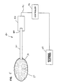
- Fig. 5 illustrates a sensing system 40 that incorporates the sensor 20 of Figures 1-3.
- the fibers 22 are electrically connected to a wire 41 by one or more electrical connectors 42 positioned at a proximal end 44 of the sensor 20.
- the wire 41 electrically connects the sensor 20 to a controller 46.
- the controller 46 can be any type of controller such as a micro-controller, a mechanical controller, a software driven controller, a hardware driven controller, a firmware driven controller, etc.
- the controller 46 is also electrically connected to a reference electrode 48.
- the reference electrode 48 preferably includes a layer of silver silver-chloride.
- the distal end 30 of the sensor 20 is placed in fluid communication with a test volume 50 of a substance containing an analyte desired to be sensed.
- the test volume 50 is the volume from which the analyte desired to be sensed can diffuse into the sensor 20 during the sensing period. With the sensor 20 so positioned, the analyte within the test volume 50 can diffuse into the sensing material 26 located adjacent to the distal end 30 of the sensor 20. Additionally, water within the test volume 50 can diffuse into the sensing material 26 such that the sensing material 26 is hydrated. A potential is then applied between the reference electrode 48 and the sensor 20.
- an electrical current will flow through the test volume 50 between the reference electrode 48 and the distal end 30 of the sensor 20.
- the current is a result of the electrolysis of the analyte in the test volume 50.
- This electrochemical reaction occurs via the redox compound in the sensing material 26 and the optional redox enzyme in the sensing material 26.
- concentration of a given analyte in the test sample can be determined.
- current measurements can be obtained by a variety of techniques including, among other things, coulometric, potentiometric, amperometric, voltammetric, and other electrochemical techniques.
- Figs. 6A-6C schematically illustrate a sensor assembly 60 for providing on-line monitoring/measurement of bioanalytes such as lactate in a patient.
- the sensor assembly 60 includes a catheter 62 (e.g., a peripheral catheter) having a catheter sheath 64 connected to a catheter hub 66 (i.e., a luer fitting).
- the sensor assembly 60 also includes an adapter 68 connected to the catheter hub 66.
- the adapter is in fluid communication with a pump 70 (e.g., a syringe 71 driven by a syringe driver (not shown)).
- the syringe 71 preferably contains a volume of calibration fluid 72.
- the sensor assembly 60 of Fig. 5 is preferably incorporated into the sensor assembly 60.
- the sensor 20 extends through the adapter 68 and into the catheter sheath 64 such that the distal end 30 of the sensor 20 is located adjacent a tip 74 of the catheter sheath 64.
- a radial spacing of at least .0015 inches exists between the outer surface of the sensor 20 and the inner surface of the sheath 64.
- the reference electrode 48 is shown positioned within the adapter 68 and both the reference electrode 48 and the sensor 20 are shown electrically connected to the controller 46.
- the syringe 71 preferably contains a calibration fluid 72.
- the calibration fluid 72 preferably includes a predetermined concentration of a calibrant such as lactate or lactate sensors or glucose for glucose sensors.
- the calibration fluid can include a variety of other components in addition to a calibrant.
- an anticoagulant such as sodium citrate can be used.
- a preferred calibration fluid comprises a solution of sodium citrate, saline, and lactate.
- lactate is only used as a calibrate if a lactate sensor is being used in the system.
- Other types of calibrates that may be used in the system include glucose, potassium, sodium, calcium, and ringers lactate.
- Fig. 6A illustrates the sensor assembly 60 at a start condition.
- the catheter sheath 64 is inserted within a patient such that blood 76 surrounds the tip 74 of the catheter sheath 64.
- the catheter sheath 64 is filled with the calibration fluid 72 such that the distal tip 30 of the sensor 20 is bathed in the calibration fluid 72.
- a diffusion zone 78 exists adjacent the catheter sheath tip 74.
- the diffusion zone 78 is the region into which blood can readily diffuse or mix even when the system is static.
- the test volume 50 of the sensing system 40 surrounds the distal end 30 of the sensor 20.
- the test volume 50 includes the volume surrounding the distal end 30 of the sensor 20 that is readily depleted of a test substance (e.g., lactate or glucose) when potential is applied between the sensor 20 and the reference electrode 48. It is preferred for the test volume 50 to not be coextensive with the diffusion zone 78. To achieve this, it is preferred for the distal end 30 of the sensor 20 to be located at least one-half millimeter away from the tip 74 of the catheter sheath 64. In certain embodiments, the distal end 30 of the sensor 20 is located in the range of 2 to 3 millimeters away from the catheter sheath tip 74.
- a test substance e.g., lactate or glucose
- the reference electrode 48 is shown positioned within the adapter 68, it will be appreciated that other configurations could also be used.
- the reference electrode 48 could comprise a skin mounted electrode positioned on the patient's skin adjacent to the catheter sheath 64.
- only two electrodes i.e., the reference electrode 48 and the sensor 20
- three electrodes e.g., a reference electrode, a counter electrode, and a worker electrode
- Exemplary wired enzyme sensors having three electrode configurations are described in United States Patent Nos. 5,264,105; 5,356,786; 5,262,035; and 5,320,725, which are hereby incorporated by reference.
- a potential can be applied between the reference electrode 48 and the sensor 20.
- the sensing material 26 begins to consume the sensed analyte (i.e., the analyte desired to be sensed or measured such as lactate or glucose) within the calibration fluid located in the test volume 50.
- Initial calibration can be obtained by monitoring the slope of decay in the current generated between the sensor 20 and the reference electrode 48. A reading is preferably taken when the sensor 20 begins to consume all of the analyte in the test volume 50 and the current begins to decline.
- a blood sample can be tested.
- the syringe plunger is drawn back such that blood 76 is drawn into the catheter sheath 64.
- sufficient blood 76 is drawn into the catheter sheath 64 to surround the distal end 30 of the sensor 20 with blood and to ensure that the test volume 50 is filled with blood.
- movement of the plunger is stopped and a potential is applied between the sensor 20 and the reference electrode 48. With the potential applied between the reference electrode 48 and the sensor 20, the sensor 20 begins to consume the sensed analyte contained within the blood 76 within the test volume 50.
- the current begins to decline and a reading is taken.
- the system is purged as shown in Fig. 6C by pushing the plunger of the syringe 71 inward causing the calibration fluid to displace the blood 76 within the sheath 64. Consequently, the blood 76 within the sheath 64 is forced back into the patient.
- the syringe 71 injects enough of the calibration fluid 72 into the system to displace about two times the volume of the catheter sheath 64. As a result, some of the calibration fluid is injected into the patient along with the blood 76.
- the senor 20 can be recalibrated as described with respect to Fig. 6A. Thereafter, the testing and purging steps can be repeated.
- the sensor 20 provides numerous advantages.
- the plurality of fibers 22 provide a large surface area for supporting the sensing material 26. Therefore, a large surface area of sensing material 26 is exposed to the test volume 50.
- the sensor 20 is capable of quickly depleting the sensed analyte within the test volume 50 thereby allowing an analyte concentration to be quickly determined.
- This rapid sensing capability is particularly advantageous for applications such as fetal monitors and intercranial monitors.
- the large surface area also prevents the sensing material 26 from quickly becoming depleted thereby lengthening the useful life of the sensor 20.
- the use of carbon fibers assists in accurately calibrating the sensor 20 because carbon is an effective heat conductor. This is significant because some calibration processes are temperature dependent. By using a heat conductive fiber, the temperature of the fiber will quickly match the temperature of a calibration fluid contained within the test volume 50. As a result, calibration inaccuracies associated with differences in temperature between the calibration fluid and the sensor 20 can be reduced.
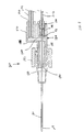
- FIGS 7 and 8 illustrate an alternative sensor assembly 160 constructed in accordance with the principles of the present invention.
- the sensor assembly 160 includes an adapter 168 that connects to a luer fitting 166 of a catheter sheath 164.
- the adapter 168 includes an insertion piece 180 that fits within the luer fitting 166, and a cap 182 that threads on the luer fitting 166 to hold the insertion piece 180 within the luer fitting 166.
- the adapter 168 also includes a two-piece manifold 184.
- the manifold 184 includes a first piece 186 having a projection 188 that extends through the cap 182 and provides a fluid-tight connection with the insertion piece 180.
- the manifold 182 also includes a second piece 190 that connects with the first piece 186.
- the second piece 190 includes a tube receiver 192.
- the first and second pieces 186 and 190 of the manifold 184 cooperate to define a flow passageway 194 (shown in Fig. 8) that extends from the tube receiver 192 to the insertion portion 180 of the adapter 168.
- the tube receiver 192 preferably receives a tube 196 coupled to a source of calibration fluid (e.g., a syringe containing calibration fluid such as the syringe 71 of Figs. 6A-6C).
- the senor 20 preferably extends through the adapter 168 and into the catheter sheath 164.
- a first electrical connector 198 is mounted at the proximal end 44 of the sensor 20.
- the first electrical connector 198 is electrically coupled to a second electrical connector 200 that is mounted at the end of a wire 202.
- the wire 202 is electrically coupled a controller such as the controller 42 of Fig. 4.
- the sensor assembly 160 does not include an internal reference electrode. Instead, the sensor assembly 160 can include an external reference electrode (e.g., a skin-mounted electrode) that is coupled to the controller.
- an external reference electrode e.g., a skin-mounted electrode
- Figure 9 illustrates a method for making the sensor 20 of Figures 1-3.
- the bundle 24 of fibers 22 is first pulled through a die 300 containing a volume of the sensing material 26 in liquid form.
- the sensing material 26 coats the outer surfaces of the fibers 22.
- the sensing material 26 can be dried at a heating station 302 (e.g., a convection heater). Thereafter, the fibers 22 coated with sensing material 26 are pulled through a sizing die 304 to compress the bundle 24 to a desired diameter. Next, the sized bundle 24 is pulled through a die 306 containing material that will form the insulating layer 28 of the sensor 20.
- the die 306 can contain a volume of liquid polymer such as polyurethane. As the bundle 24 is pulled through the die 306, the insulating layer material coats the outside of the bundle.
- the bundle can be moved through a curing station 308 (e.g., an ultraviolet curing station) where the insulating layer 28 is cured. Finally, the bundle 24 is moved through a cutting station 310 where the bundle 24 is cut into pieces having desired lengths.
- a curing station 308 e.g., an ultraviolet curing station
- the above-described method provides numerous advantages. For example, the method allows a relatively large number of sensors 20 to be manufactured in a relatively short amount of time. Also, the above-described method is able to provide sensors having similar operating characteristics from batch to batch.
- Fig. 10 illustrates a sensor system 119 constructed in accordance with the principles of the present invention.
- the sensor system 119 includes a sensor 120 having a plurality of electrically conductive fibers 122.
- the fibers 122 are coated (i.e., covered or encased) with a sensing material 126.
- An insulating layer 128 e.g., a sheath surrounds or encloses the plurality of fibers 122 to form an exterior boundary about the fibers 122.
- the fibers 122 of the sensor 120 are arranged in a sheet-like configuration.
- the fibers 122 form a fabric having a square weave-type mesh.
- the sheet can be formed by a matte of randomly arranged fibers, or the fibers can be arranged in a weave or pattern.
- the fibers 122 are electrically conductive.
- the fibers 122 are made of carbonized nylon.
- the fibers are arranged in the form of a carbonized nylon fabric.
- a carbonized nylon fabric is sold by Sefar America, Inc. under the trade name "Carbotex" (e.g., product numbers C382/137 and C3130/49).
- These particular illustrative fabrics include monofilament fibers approximately 45 microns in diameter.
- These non-limiting fabrics also include square weaves with pore sizes of 130 microns and 82 microns respectively, and a thickness of about 92 microns.
- the monofilament surfaces are evenly carbonized to a depth of a few microns with minimal discontinuities, making the surface particularly suitable for forming the substrate for wired enzyme biosensors.
- the fibers have diameters less than 90 microns. More preferably, the fibers have diameters less than 60 microns. Most preferably, the fibers have diameters no greater than 45 microns.
- the senor 120 is electrically connected to a controller 146.
- the controller 146 is also electrically connected to a reference electrode 148.
- the controller 146 and the reference electrode 148 preferably operate in a manner similar to the reference electrode and controller previously described with respect to the embodiment of Fig. 5.
- the insulating layer 128 of the sensor 120 performs the same function as the insulating layer 28 previously described with respect to the sensor 20 of Figs. 1-3.
- the sensing layer 126 of the sensor 120 preferably performs these same function as the sensing layer 126 of the sensor 20 of Figs. 1-3. Accordingly, the descriptions pertaining to the insulating layer 28 and the sensing material 26 also apply to the insulating layer 128 and the sensing material 126.
- the insulating layer 128 preferably defines an opening for allowing a substance desired to be sensed to be transported or otherwise conveyed to the sensing material 126.
- the sensor 120 can have a distal end 130 that is transversely cut.
- the insulating layer 128 defines an opening 132 (shown in Fig. 11) through which the substance desired to be sensed can be transported.
- the opening 132 is configured to allow an analyte such as lactate or glucose to diffuse into the sensing material 126 that surrounds the fibers 122.
- FIG. 12 illustrates an alternative sensor 220 having an opening 234 that is transversely cut entirely through a mid-region of the sensor 220.
- an outer boundary of the sensor 220 is sealed.
- Electrically conductive fibers 222 coated with sensing material are enclosed within an insulating sheath 228.
- the opening 234 through the sheath 228 allows regions of the fibers 222 adjacent to the middle of the sensor 220 to be exposed to a fluid containing an analyte desired to be sensed.
- FIG. 13 illustrates a further sensor 320 constructed in accordance with the principles of the present invention.
- a sensor 320 includes a plurality of electrically conductive fibers 322 located within an insulating sheath 328.
- the fibers 322 are preferably covered with a sensing material.
- the sensing material is exposed to fluid containing an analyte desired to be sensed by a plurality of openings 334 defined though the insulating sheath 328.
- a sensing chemistry is deposited on a region of a mesh of electrically conductive fibers such that the mesh within the region is preferably substantially evenly coated on all aspects.
- the mesh can be laminated to a carrier film such as a mylar or other suitable substrate using an elastomeric/adhesive layer that bonds to the substrate and encapsulates the mesh.
- a carrier film such as a mylar or other suitable substrate using an elastomeric/adhesive layer that bonds to the substrate and encapsulates the mesh.
- at least one area of the mesh is left exposed at some location remote from that which is covered with the sensing chemistry to provide an electrical contact surface for the sensor output.
- the sensor profile i.e., the outer shape of the sensor
- the sensor profile is then slit or otherwise cut (e.g., die cut) from the fabric in such a manner as to have at least one cutting plain that cuts through the portion of the mesh that is coated with sensing chemistry.
- the resultant cut ends of the coated fabric form the working electrode surfaces and are analogous in function to the cut distal end of the carbon fiber bundle described with respect to Figs. 1-5.
- the back surface of the carrier film can be coated with silver silver chloride to provide a reference electrode.
- the reference electrode can comprise a separate skin-mounted electrode.
- Wired enzyme sensors utilizing a fiber mesh substrate can have various medical applications. For example, if used as lactate sensors, sensors such as those shown in Figs. 10-13 can be used to determine perfusion levels in surgical procedures. For example, such sensors can be used in combination with products such as "surgical patties.” Surgical patties are soft sterile textile pads that are positioned behind the retractor blades of surgical instruments. Such instruments, sometimes known as “spreaders", are used to hold overbearing tissue away from a surgeon's line of vision. Pressure exerted by the retractor blades against the tissue prevents adequate perfusion of the immediate contact area, often leading to cellular necrosis.
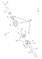
- Fig. 14 schematically illustrates a sensing system configured for allowing a physician to monitor the lactate level in tissue that is being compressed by a retractor blade 400.
- a sensor 402 e.g., a sensor configured similar to the sensors 120, 220 or 320 of Figs. 10-13
- the sensor comprises a wired enzyme sensor including a sensing material capable of oxidizing or reducing lactate.
- the sensor 402 can include a redox compound and a redox enzyme that catalyzes an oxidation or reduction of lactate (e.g., lactate oxidase or lactate dehydrogenase).
- the sensor 402 is preferably mounted between the retractor blade 400 and a textile pad 404.
- blood from the tissue being compressed by the retractor blade 400 defuses through the pad 404 to reach the sensor 402.
- a potential is preferably applied between a reference electrode 405 (e.g., a skin-mounted electrode) and the sensor 402.
- a reference electrode 405 e.g., a skin-mounted electrode
- an electrical current will flow through the blood sample between the reference electrode 406 and the exposed working electrodes of the sensor 402.
- the current is the result of the electrolysis of lactate within the sample.
- This electrochemical reaction occurs via the redox compound in the sensing material at the working electrodes of the sensor 402 and the optional redox enzyme in the sensing material.
- a controller 408 is provided for measuring the current flow generated at a given potential.
- the controller 408 can calculate a lactate concentration in the test sample. Consequently, by using the sensing system 401 in combination with the retractor blade 400, a surgeon can constantly monitor lactate level in the tissue being compressed by the retractor blade 400. If lactate levels begin to rise, the surgeon can remove the retractor blade 400 before the tissue is permanently damaged.
- all of the fibers of the sensor can be electrically conductive.
- fibers oriented in one direction can be conductive, while fibers oriented in a perpendicular direction can be nonconductive.
Landscapes
- Life Sciences & Earth Sciences (AREA)
- Health & Medical Sciences (AREA)
- Chemical & Material Sciences (AREA)
- Engineering & Computer Science (AREA)
- Organic Chemistry (AREA)
- Physics & Mathematics (AREA)
- Biophysics (AREA)
- Proteomics, Peptides & Aminoacids (AREA)
- Immunology (AREA)
- Molecular Biology (AREA)
- General Health & Medical Sciences (AREA)
- Wood Science & Technology (AREA)
- Zoology (AREA)
- Biochemistry (AREA)
- Analytical Chemistry (AREA)
- Biomedical Technology (AREA)
- Hematology (AREA)
- Bioinformatics & Cheminformatics (AREA)
- General Physics & Mathematics (AREA)
- Genetics & Genomics (AREA)
- Pathology (AREA)
- Microbiology (AREA)
- Biotechnology (AREA)
- General Engineering & Computer Science (AREA)
- Food Science & Technology (AREA)
- Medicinal Chemistry (AREA)
- Urology & Nephrology (AREA)
- Ecology (AREA)
- Chemical Kinetics & Catalysis (AREA)
- Electrochemistry (AREA)
- Measurement Of The Respiration, Hearing Ability, Form, And Blood Characteristics Of Living Organisms (AREA)
- Investigating Or Analyzing Materials By The Use Of Electric Means (AREA)
- Multicomponent Fibers (AREA)
- Laminated Bodies (AREA)
- Measuring Or Testing Involving Enzymes Or Micro-Organisms (AREA)
Abstract
Description
- This invention relates to sensors for measuring bioanalytes and to methods for making such sensors. More particularly, the invention relates to sensors for sensing lactate and to methods for making such sensors.
- Lactate is a small molecule that is produced by all tissues and organs of a patient's body that are in "distress." Wherever in the patient's body the demands for oxygen exceed the supply, then a state of low perfusion exists and lactate is produced. For example, lactate is produced if a patient is bleeding, if a patient's heart is failing, if a person's limb is in danger of being lost, or if a person is not getting enough oxygen to breathe. Thus many life and limb threatening clinical states produce elevated blood lactate levels, even in the face of adequate oxygen delivery to the patient. It is a matter of oxygen supply and metabolic demand.
- At the cellular level, lactate is inversely proportional to the vital cellular energy stores of adenosine triphosphate and is produced within six seconds of inadequate perfusion or cellular injury. It is thus an ideal biochemical monitor of cellular viability at the tissue level, and of patient viability at the systemic level.
- Clinically, the dire significance of elevated and rising blood lactate values is known. Trauma physicians and clinical evidence support the hypothesis that a simple, inexpensive, continuous, monitor of lactate in the trauma setting, will save lives by providing timely, life-saving information that will help dictate triage and therapy. For example, an emergency room patient who has a blood lactate level of 4mM has a 92% mortality rate within the next 24 hours. If this level is 6mM, then the mortality rate rises to 98%. In animal experiments, blood lactate levels begin to rise within minutes of hemorrhage, and conversely, begin to fall just as quickly with adequate resuscitation. In multivariate analysis, blood lactate is the best indicator of the degree of shock (superior to blood pressure, heart rate, urine output, base deficit, blood gas and Swan-Ganz data) and is proportional to the shed blood volume. Blood lactate levels correlate with a trauma patient's chances of survival. Therapy that fails to control a patient's increasing lactate levels must be modified or additional diagnoses quickly sought.
- Sensors have been developed for detecting lactate concentrations in a given fluid sample. For example, United States Patent Nos. 5,264,105; 5,356,786; 5,262,035; and 5,320,725 disclose wired enzyme sensors for detecting analytes such as lactate or glucose. EP-A592805 discloses a sensor electrode comprising a plurality of carbon fibres that are dipped in a solution containing a reactant. The carbon electrode is impregnated with the solution and is covered with an insulating outer layer. Because the reactant is liquid no voids are defined between the covered fibres.
- One aspect of the present invention relates to a sensor including a plurality of electrically conductive fibers. The sensor also includes a sensing material coating at least some of the fibers, and an insulating layer positioned about the electrically conductive fibers. The conductive fibers provide a large substrate surface area for supporting the sensing material. Thus, the sensor has a large surface area of sensing material even at small sizes. This large surface area of sensing material provides numerous advantages. For example, the large surface area assists in improving the response/sensing time of the sensor. Also, the large surface area assists in lengthening the useful life of the sensor.
- Another aspect of the present invention relates to a surgical retractor device including a surgical retractor blade, and a lactate sensor positioned adjacent to the retractor blade for sensing lactate levels in tissue being compressed by the retractor blade. The lactate sensor allows a surgeon to monitor and detect when tissue being compressed by the retractor blade begins to become stressed.
- These and various other features which characterize the invention are pointed out with particularity in the attached claims. For a better understanding of the invention, it's advantages, and objectives obtained by its use, reference should be made to the drawings and to the accompanying description, in which there is illustrated and described preferred aspects of the present invention.
- The accompanying drawings, which are incorporated in and constitute a part of this specification, illustrate several aspects of the invention and together with the description, serve to explain the principles of the invention. A brief description of the drawings is as follows:
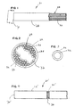
- Fig. 1 is an elevational view of a sensor constructed in accordance with the principles of the present invention;
- Fig. 2 is a cross-sectional view taken along section line 2-2 of Fig. 1 with only a portion of the fiber ends depicted;
- Fig. 3 is a detailed end view of one of the fibers of the sensor of Fig. 1, the fiber is coated with a sensing material;
- Fig. 4 is a elevational view of an alternative sensor constructed in accordance with the principles of the present invention;
- Fig. 5 is a schematic view of a sensor system incorporating the sensor of Fig. 1;
- Fig. 6A is a schematic view of a sensor assembly constructed in accordance with the principles of the present invention, the sensor assembly is shown in a start or calibration condition;
- Fig. 6B illustrates the sensor assembly of Fig. 6A in a test condition;
- Fig. 6C illustrates the sensor assembly of Fig. 6A in a purge condition;
- Fig. 7 is an exploded, perspective view of an alternative sensor assembly constructed in accordance with the principles of the present invention;
- Fig. 8 is a longitudinal cross-section view of the assembled sensor assembly of Fig. 7;
- Fig. 9 is a schematic illustration of a method for manufacturing a sensor such as the sensor of Fig. 1;
- Fig. 10 illustrates another sensor system constructed in accordance with the principles of the present invention;
- Fig. 11 is a partial left-end view of the sensor of Fig. 10;
- Fig. 12 is a plan view of a further sensor constructed in accordance with the principles of the present invention;
- Fig. 13 is an additional sensor constructed in accordance with the principles of the present invention; and
- Fig. 14 schematically illustrates a system for the lactate level in tissue that is compressed by a surgical retractor.
- Reference will now be made in detail to exemplary aspects of the present invention which are illustrated in the accompanying drawings. Wherever possible, the same reference numbers will be used throughout the drawings to refer to the same or like parts.
- An aspect of the present invention relates to sensors for providing on-line monitoring/measurement of bioanalytes in a patient. One particular aspect of the present invention relates to a sensor for providing on-line measurement of lactate concentrations in a patient.
- Figs. 1-3 illustrate a
sensor 20 constructed in accordance with the principles of the present invention. Thesensor 20 includes a plurality of electricallyconductive fibers 22 arranged in abundle 24. Thefibers 22 in thebundle 24 are coated (i.e. covered) with asensing material 26. An insulatinglayer 28 surrounds thebundle 24. - The
fibers 22 of thesensor 20 are made of an electrically conductive material. A preferred material of thefibers 22 is carbon. For example, in one nonlimiting embodiment of the present invention, thefibers 22 are made of 92-98% carbon. Thefibers 22 will each typically have a relatively small diameter. For example, in one particular nonlimiting environment, thefibers 22 can each have a diameter in the range of 5-10 microns. It will be appreciated that the illustrated embodiments are not drawn to scale. While any number offibers 22 could be used to form thebundle 24, it is preferred for many fibers (e.g., 1,000 to 3,000 fibers per bundle) to be used. Preferably, thebundle 24 has a diameter in the range of .010 - .015 inches. - The
sensing material 26 preferably includes a redox compound or mediator. The term redox compound is used herein to mean a compound that can be oxidized or reduced. Exemplary redox compounds include transition metal complexes with organic ligands. Preferred redox compounds/mediators are osmium transition metal complexes with one or more ligands having a nitrogen containing heterocycle such as 2, 2'-bipyridine. The sensing material can also include a redox enzyme. A redox enzyme is an enzyme that catalyzes an oxidation or reduction of an analyte. For example, a glucose oxidase or glucose dehydrogenase can be used when the analyte is glucose. Also, a lactate oxidase or lactate dehydrogenase fills this role when the analyte is lactate. In systems such as the one being described, these enzymes catalyze the electrolysis of an analyte by transferring electrons between the analyte and the electrode via the redox compound. - The insulating
layer 28 of thesensor 20 preferably serves numerous functions to thesensor 20. For example, the insulatinglayer 28 preferably electrically insulates thefibers 22. Additionally, the insulatinglayer 28 preferably provides mechanical strength for maintaining thefibers 22 in thebundle 24. Additionally, the insulatinglayer 28 preferably forms a barrier about thefibers 22 that prevents the uncontrolled transport of a substance desired to be sensed (e.g., an analyte such as glucose or lactate). In one nonlimiting embodiment, the insulatinglayer 28 is made of a polymeric material such as polyurethane. - The insulating
layer 28 preferably defines an opening for allowing a substance desired to be sensed to be transported or otherwise conveyed to thesensing material 26. For example, thesensor 20 can include adistal end 30 that is transversely cut. At thedistal end 30, the insulatinglayer 28 defines an opening 32 (shown in Fig. 2) through which the material desired to be sensed can be transported. For example, theopening 32 is configured to allow an analyte such as lactate or glucose to diffuse into thesensing material 26 that surrounds thefibers 22. - It will be appreciated that openings can be formed at various locations along the length of the
sensor 20. For example, Fig. 4 illustrates an alternative sensor 20' having anopening 34 formed at an intermediate location along the length of the sensor 20'. Theopening 34 is arranged in the form of an annular cut form through an insulating layer 28' of the sensor 20'. Fibers 22' coated with sensing material are located within the insulating layer 28'. Theopening 34 exposes a region of the sensing material to the exterior of the sensor 20'. Consequently, theopening 34 provides a passage for allowing a substance desired to be sensed to diffuse into the region of exposed sensing material. The sensor 20' preferably also includes a distal end 30' that is closed or otherwise sealed by the insulating layer 28'. - Fig. 5 illustrates a sensing system 40 that incorporates the
sensor 20 of Figures 1-3. Thefibers 22 are electrically connected to awire 41 by one or moreelectrical connectors 42 positioned at aproximal end 44 of thesensor 20. Thewire 41 electrically connects thesensor 20 to acontroller 46. Thecontroller 46 can be any type of controller such as a micro-controller, a mechanical controller, a software driven controller, a hardware driven controller, a firmware driven controller, etc. Thecontroller 46 is also electrically connected to areference electrode 48. Thereference electrode 48 preferably includes a layer of silver silver-chloride. - In use of the sensing system 40, the
distal end 30 of thesensor 20 is placed in fluid communication with atest volume 50 of a substance containing an analyte desired to be sensed. Thetest volume 50 is the volume from which the analyte desired to be sensed can diffuse into thesensor 20 during the sensing period. With thesensor 20 so positioned, the analyte within thetest volume 50 can diffuse into thesensing material 26 located adjacent to thedistal end 30 of thesensor 20. Additionally, water within thetest volume 50 can diffuse into thesensing material 26 such that thesensing material 26 is hydrated. A potential is then applied between thereference electrode 48 and thesensor 20. When the potential is applied, an electrical current will flow through thetest volume 50 between thereference electrode 48 and thedistal end 30 of thesensor 20. The current is a result of the electrolysis of the analyte in thetest volume 50. This electrochemical reaction occurs via the redox compound in thesensing material 26 and the optional redox enzyme in thesensing material 26. By measuring the current flow generated at a given potential, the concentration of a given analyte in the test sample can be determined. Those skilled in the art will recognize that current measurements can be obtained by a variety of techniques including, among other things, coulometric, potentiometric, amperometric, voltammetric, and other electrochemical techniques. - Figs. 6A-6C schematically illustrate a
sensor assembly 60 for providing on-line monitoring/measurement of bioanalytes such as lactate in a patient. Thesensor assembly 60 includes a catheter 62 (e.g., a peripheral catheter) having acatheter sheath 64 connected to a catheter hub 66 (i.e., a luer fitting). Thesensor assembly 60 also includes anadapter 68 connected to thecatheter hub 66. The adapter is in fluid communication with a pump 70 (e.g., asyringe 71 driven by a syringe driver (not shown)). Thesyringe 71 preferably contains a volume ofcalibration fluid 72. - The
sensor assembly 60 of Fig. 5 is preferably incorporated into thesensor assembly 60. For example, as shown in Figs. 6A-6C, thesensor 20 extends through theadapter 68 and into thecatheter sheath 64 such that thedistal end 30 of thesensor 20 is located adjacent atip 74 of thecatheter sheath 64. In certain embodiments, a radial spacing of at least .0015 inches exists between the outer surface of thesensor 20 and the inner surface of thesheath 64. Also, thereference electrode 48 is shown positioned within theadapter 68 and both thereference electrode 48 and thesensor 20 are shown electrically connected to thecontroller 46. - As indicated above, the
syringe 71 preferably contains acalibration fluid 72. Thecalibration fluid 72 preferably includes a predetermined concentration of a calibrant such as lactate or lactate sensors or glucose for glucose sensors. The calibration fluid can include a variety of other components in addition to a calibrant. For example, an anticoagulant such as sodium citrate can be used. A preferred calibration fluid comprises a solution of sodium citrate, saline, and lactate. Of course, lactate is only used as a calibrate if a lactate sensor is being used in the system. Other types of calibrates that may be used in the system include glucose, potassium, sodium, calcium, and ringers lactate. - Fig. 6A illustrates the
sensor assembly 60 at a start condition. As shown in Fig. 6A, thecatheter sheath 64 is inserted within a patient such thatblood 76 surrounds thetip 74 of thecatheter sheath 64. At the start condition, thecatheter sheath 64 is filled with thecalibration fluid 72 such that thedistal tip 30 of thesensor 20 is bathed in thecalibration fluid 72. It will be appreciated that with thecatheter sheath 64 inserted within the patient, adiffusion zone 78 exists adjacent thecatheter sheath tip 74. Thediffusion zone 78 is the region into which blood can readily diffuse or mix even when the system is static. - Still referring to Fig. 6A, the
test volume 50 of the sensing system 40 surrounds thedistal end 30 of thesensor 20. Thetest volume 50 includes the volume surrounding thedistal end 30 of thesensor 20 that is readily depleted of a test substance (e.g., lactate or glucose) when potential is applied between thesensor 20 and thereference electrode 48. It is preferred for thetest volume 50 to not be coextensive with thediffusion zone 78. To achieve this, it is preferred for thedistal end 30 of thesensor 20 to be located at least one-half millimeter away from thetip 74 of thecatheter sheath 64. In certain embodiments, thedistal end 30 of thesensor 20 is located in the range of 2 to 3 millimeters away from thecatheter sheath tip 74. - While the
reference electrode 48 is shown positioned within theadapter 68, it will be appreciated that other configurations could also be used. For example, thereference electrode 48 could comprise a skin mounted electrode positioned on the patient's skin adjacent to thecatheter sheath 64. Furthermore, as shown herein, only two electrodes (i.e., thereference electrode 48 and the sensor 20) are used in thesensor assembly 60. It will be appreciated that in alternative embodiments, three electrodes (e.g., a reference electrode, a counter electrode, and a worker electrode) can be used. Exemplary wired enzyme sensors having three electrode configurations are described in United States Patent Nos. 5,264,105; 5,356,786; 5,262,035; and 5,320,725, which are hereby incorporated by reference. - Referring again to Fig. 6A, with the
distal end 30 of thesensor 20 bathed in the calibration fluid, a potential can be applied between thereference electrode 48 and thesensor 20. When the potential is applied between thesensor 20 and thereference electrode 48, thesensing material 26 begins to consume the sensed analyte (i.e., the analyte desired to be sensed or measured such as lactate or glucose) within the calibration fluid located in thetest volume 50. Initial calibration can be obtained by monitoring the slope of decay in the current generated between thesensor 20 and thereference electrode 48. A reading is preferably taken when thesensor 20 begins to consume all of the analyte in thetest volume 50 and the current begins to decline. - After the
sensor 20 has been calibrated, a blood sample can be tested. For example, as shown in Fig. 6B, to test a blood sample, the syringe plunger is drawn back such thatblood 76 is drawn into thecatheter sheath 64. Preferably,sufficient blood 76 is drawn into thecatheter sheath 64 to surround thedistal end 30 of thesensor 20 with blood and to ensure that thetest volume 50 is filled with blood. Once sufficient blood has been drawn into thecatheter sheath 64, movement of the plunger is stopped and a potential is applied between thesensor 20 and thereference electrode 48. With the potential applied between thereference electrode 48 and thesensor 20, thesensor 20 begins to consume the sensed analyte contained within theblood 76 within thetest volume 50. When thesensor 20 approaches consuming all of the analyte within thetest volume 50, the current begins to decline and a reading is taken. - Thereafter, the system is purged as shown in Fig. 6C by pushing the plunger of the
syringe 71 inward causing the calibration fluid to displace theblood 76 within thesheath 64. Consequently, theblood 76 within thesheath 64 is forced back into the patient. Preferably, thesyringe 71 injects enough of thecalibration fluid 72 into the system to displace about two times the volume of thecatheter sheath 64. As a result, some of the calibration fluid is injected into the patient along with theblood 76. - After the system has been purged, the
sensor 20 can be recalibrated as described with respect to Fig. 6A. Thereafter, the testing and purging steps can be repeated. - The
sensor 20 provides numerous advantages. For example, the plurality offibers 22 provide a large surface area for supporting thesensing material 26. Therefore, a large surface area of sensingmaterial 26 is exposed to thetest volume 50. As a result, thesensor 20 is capable of quickly depleting the sensed analyte within thetest volume 50 thereby allowing an analyte concentration to be quickly determined. This rapid sensing capability is particularly advantageous for applications such as fetal monitors and intercranial monitors. The large surface area also prevents thesensing material 26 from quickly becoming depleted thereby lengthening the useful life of thesensor 20. Furthermore, the use of carbon fibers assists in accurately calibrating thesensor 20 because carbon is an effective heat conductor. This is significant because some calibration processes are temperature dependent. By using a heat conductive fiber, the temperature of the fiber will quickly match the temperature of a calibration fluid contained within thetest volume 50. As a result, calibration inaccuracies associated with differences in temperature between the calibration fluid and thesensor 20 can be reduced. - Figures 7 and 8 illustrate an
alternative sensor assembly 160 constructed in accordance with the principles of the present invention. Thesensor assembly 160 includes anadapter 168 that connects to a luer fitting 166 of acatheter sheath 164. Theadapter 168 includes aninsertion piece 180 that fits within the luer fitting 166, and acap 182 that threads on the luer fitting 166 to hold theinsertion piece 180 within theluer fitting 166. Theadapter 168 also includes a two-piece manifold 184. The manifold 184 includes afirst piece 186 having aprojection 188 that extends through thecap 182 and provides a fluid-tight connection with theinsertion piece 180. The manifold 182 also includes asecond piece 190 that connects with thefirst piece 186. Thesecond piece 190 includes atube receiver 192. The first andsecond pieces tube receiver 192 to theinsertion portion 180 of theadapter 168. In use, thetube receiver 192 preferably receives atube 196 coupled to a source of calibration fluid (e.g., a syringe containing calibration fluid such as thesyringe 71 of Figs. 6A-6C). - Still referring to Figures 7 and 8, the
sensor 20 preferably extends through theadapter 168 and into thecatheter sheath 164. A firstelectrical connector 198 is mounted at theproximal end 44 of thesensor 20. The firstelectrical connector 198 is electrically coupled to a secondelectrical connector 200 that is mounted at the end of awire 202. Preferably, thewire 202 is electrically coupled a controller such as thecontroller 42 of Fig. 4. - It is noted that the
sensor assembly 160 does not include an internal reference electrode. Instead, thesensor assembly 160 can include an external reference electrode (e.g., a skin-mounted electrode) that is coupled to the controller. - Figure 9 illustrates a method for making the
sensor 20 of Figures 1-3. In practicing the method, thebundle 24 offibers 22 is first pulled through adie 300 containing a volume of thesensing material 26 in liquid form. As thebundle 24 is pulled through thedie 300, thesensing material 26 coats the outer surfaces of thefibers 22. - After the
sensing material 26 has been applied to thefibers 22, thesensing material 26 can be dried at a heating station 302 (e.g., a convection heater). Thereafter, thefibers 22 coated withsensing material 26 are pulled through a sizing die 304 to compress thebundle 24 to a desired diameter. Next, thesized bundle 24 is pulled through adie 306 containing material that will form the insulatinglayer 28 of thesensor 20. For example, thedie 306 can contain a volume of liquid polymer such as polyurethane. As thebundle 24 is pulled through thedie 306, the insulating layer material coats the outside of the bundle. After the insulatinglayer 28 has been coated around the exterior of thebundle 24, the bundle can be moved through a curing station 308 (e.g., an ultraviolet curing station) where the insulatinglayer 28 is cured. Finally, thebundle 24 is moved through a cuttingstation 310 where thebundle 24 is cut into pieces having desired lengths. - The above-described method provides numerous advantages. For example, the method allows a relatively large number of
sensors 20 to be manufactured in a relatively short amount of time. Also, the above-described method is able to provide sensors having similar operating characteristics from batch to batch. - Fig. 10 illustrates a
sensor system 119 constructed in accordance with the principles of the present invention. Thesensor system 119 includes asensor 120 having a plurality of electricallyconductive fibers 122. As best shown in Fig. 11, thefibers 122 are coated (i.e., covered or encased) with asensing material 126. An insulating layer 128 (e.g., a sheath) surrounds or encloses the plurality offibers 122 to form an exterior boundary about thefibers 122. - The
fibers 122 of thesensor 120 are arranged in a sheet-like configuration. For example, as shown in Fig. 10, thefibers 122 form a fabric having a square weave-type mesh. However, in alternative embodiments, the sheet can be formed by a matte of randomly arranged fibers, or the fibers can be arranged in a weave or pattern. Thefibers 122 are electrically conductive. For example, in one embodiment, thefibers 122 are made of carbonized nylon. - In one non-limiting embodiment of the present invention, the fibers are arranged in the form of a carbonized nylon fabric. One exemplary type of fabric is sold by Sefar America, Inc. under the trade name "Carbotex" (e.g., product numbers C382/137 and C3130/49). These particular illustrative fabrics include monofilament fibers approximately 45 microns in diameter. These non-limiting fabrics also include square weaves with pore sizes of 130 microns and 82 microns respectively, and a thickness of about 92 microns. Preferably, the monofilament surfaces are evenly carbonized to a depth of a few microns with minimal discontinuities, making the surface particularly suitable for forming the substrate for wired enzyme biosensors. Preferably, the fibers have diameters less than 90 microns. More preferably, the fibers have diameters less than 60 microns. Most preferably, the fibers have diameters no greater than 45 microns.
- Referring back to Fig. 10, the
sensor 120 is electrically connected to acontroller 146. Thecontroller 146 is also electrically connected to a reference electrode 148. Thecontroller 146 and the reference electrode 148 preferably operate in a manner similar to the reference electrode and controller previously described with respect to the embodiment of Fig. 5. - The insulating
layer 128 of thesensor 120 performs the same function as the insulatinglayer 28 previously described with respect to thesensor 20 of Figs. 1-3. Similarly, thesensing layer 126 of thesensor 120 preferably performs these same function as thesensing layer 126 of thesensor 20 of Figs. 1-3. Accordingly, the descriptions pertaining to the insulatinglayer 28 and thesensing material 26 also apply to the insulatinglayer 128 and thesensing material 126. - The insulating
layer 128 preferably defines an opening for allowing a substance desired to be sensed to be transported or otherwise conveyed to thesensing material 126. For example, thesensor 120 can have adistal end 130 that is transversely cut. At thedistal end 130, the insulatinglayer 128 defines an opening 132 (shown in Fig. 11) through which the substance desired to be sensed can be transported. For example, the opening 132 is configured to allow an analyte such as lactate or glucose to diffuse into thesensing material 126 that surrounds thefibers 122. - It will be appreciated that alternative sensors can have access openings located at a variety of different locations. For example, Fig. 12 illustrates an
alternative sensor 220 having an opening 234 that is transversely cut entirely through a mid-region of thesensor 220. Preferably, an outer boundary of thesensor 220 is sealed. Electricallyconductive fibers 222 coated with sensing material are enclosed within an insulating sheath 228. The opening 234 through the sheath 228 allows regions of thefibers 222 adjacent to the middle of thesensor 220 to be exposed to a fluid containing an analyte desired to be sensed. - Fig. 13 illustrates a
further sensor 320 constructed in accordance with the principles of the present invention. Asensor 320 includes a plurality of electricallyconductive fibers 322 located within an insulatingsheath 328. Thefibers 322 are preferably covered with a sensing material. The sensing material is exposed to fluid containing an analyte desired to be sensed by a plurality ofopenings 334 defined though the insulatingsheath 328. - To fabricate the sensor of Figs. 10 and 11, a sensing chemistry is deposited on a region of a mesh of electrically conductive fibers such that the mesh within the region is preferably substantially evenly coated on all aspects. Next, the mesh can be laminated to a carrier film such as a mylar or other suitable substrate using an elastomeric/adhesive layer that bonds to the substrate and encapsulates the mesh. Preferably, at least one area of the mesh is left exposed at some location remote from that which is covered with the sensing chemistry to provide an electrical contact surface for the sensor output. The sensor profile (i.e., the outer shape of the sensor) is then slit or otherwise cut (e.g., die cut) from the fabric in such a manner as to have at least one cutting plain that cuts through the portion of the mesh that is coated with sensing chemistry. The resultant cut ends of the coated fabric form the working electrode surfaces and are analogous in function to the cut distal end of the carbon fiber bundle described with respect to Figs. 1-5. For some applications, the back surface of the carrier film can be coated with silver silver chloride to provide a reference electrode. Alternatively, the reference electrode can comprise a separate skin-mounted electrode.
- Wired enzyme sensors utilizing a fiber mesh substrate can have various medical applications. For example, if used as lactate sensors, sensors such as those shown in Figs. 10-13 can be used to determine perfusion levels in surgical procedures. For example, such sensors can be used in combination with products such as "surgical patties." Surgical patties are soft sterile textile pads that are positioned behind the retractor blades of surgical instruments. Such instruments, sometimes known as "spreaders", are used to hold overbearing tissue away from a surgeon's line of vision. Pressure exerted by the retractor blades against the tissue prevents adequate perfusion of the immediate contact area, often leading to cellular necrosis.
- Fig. 14 schematically illustrates a sensing system configured for allowing a physician to monitor the lactate level in tissue that is being compressed by a retractor blade 400. A sensor 402 (e.g., a sensor configured similar to the
sensors sensor 402 can include a redox compound and a redox enzyme that catalyzes an oxidation or reduction of lactate (e.g., lactate oxidase or lactate dehydrogenase). Thesensor 402 is preferably mounted between the retractor blade 400 and atextile pad 404. In use, blood from the tissue being compressed by the retractor blade 400 defuses through thepad 404 to reach thesensor 402. A potential is preferably applied between a reference electrode 405 (e.g., a skin-mounted electrode) and thesensor 402. When the potential is applied, an electrical current will flow through the blood sample between thereference electrode 406 and the exposed working electrodes of thesensor 402. The current is the result of the electrolysis of lactate within the sample. This electrochemical reaction occurs via the redox compound in the sensing material at the working electrodes of thesensor 402 and the optional redox enzyme in the sensing material. Acontroller 408 is provided for measuring the current flow generated at a given potential. By measuring the current flow, thecontroller 408 can calculate a lactate concentration in the test sample. Consequently, by using thesensing system 401 in combination with the retractor blade 400, a surgeon can constantly monitor lactate level in the tissue being compressed by the retractor blade 400. If lactate levels begin to rise, the surgeon can remove the retractor blade 400 before the tissue is permanently damaged. - In the embodiments shown in Figs. 10-13, all of the fibers of the sensor can be electrically conductive. Alternatively, it may be desirable to alternate conductive and nonconductive fibers, or to provide specific regions of conductive fibers and other regions of nonconductive fibers. In still other embodiments, fibers oriented in one direction can be conductive, while fibers oriented in a perpendicular direction can be nonconductive. By varying the relative positioning of the conductive and nonconductive fibers, the operating characteristics of the sensors can be adjusted or otherwise modified.
- With regard to the foregoing description, it is to be understood that changes may be made in detail, especially in matters of the construction materials employed and the shape, size and arrangement of the parts without departing from the scope of the present invention. Also, it should be noted that the sensors depicted in the drawings of this specification have been shown in a diagrammatic fashion and have not been drawn to scale. It is intended that the specification and depicted aspects be considered exemplary only, with a true scope of the invention being indicated by the broad meaning of the following claim.
Claims (22)
- A sensor comprising :a plurality electrically conductive fibers (22);a dry sensing material (26) coating the outer surface of at least some of the fibers; andan insulating layer (28) surrounding the plurality of electrically conductive fibers characterized by voids between the fibers that allow the analyte to diffuse into the sensor.
- The sensor of claim 1, wherein the insulating layer forms an analyte barrier that surrounds the conductive fibers.
- The sensor of claim 2, wherein the analyte barrier defines at least one opening for allowing an analyte to access the sensing material.
- The sensor of claim 1, wherein the insulating layer comprises an electrical insulator.
- The sensor of claim 1, wherein the insulating layer comprises polyurethane.
- The sensor of claim 1, wherein the conductive fibers comprise carbon.
- The sensor of claim 1, wherein the sensing material includes a redox compound.
- The sensor of claim 7, wherein the redox compound comprises a transition metal complex with one or more organic ligands.
- The sensor of claim 7, wherein the sensing material includes a redox enzyme.
- The sensor of claim 9, wherein the redox enzyme catalyzes the oxidation or reduction of an analyte.
- The sensor of claim 10, wherein the analyte comprises lactate.
- The sensor of claim 11, wherein the redox enzyme is selected from the group of lactate oxidase and lactate dehydrogenase.
- The sensor of claim 10, wherein the analyte comprises glucose.
- The sensor of claim 13, wherein the redox enzyme is selected from the group of glucose oxidase and glucose dehydrogenase.
- The sensor of claim 1, wherein the fibers form a sheet.
- The sensor of claim 1, wherein the fibers are interwoven.
- The sensor of claim 1, wherein the fibers form a piece of fabric.
- The sensor of claim 2, wherein the analyte barrier defines a plurality of openings for allowing an analyte to access the sensing material.
- A retractor device comprising:a surgical retractor blade; anda lactate sensor positioned adjacent to the retractor blade for sensing lactate levels in tissue being compressed by the retractor blade, the lactate sensor comprising:a plurality of electrically conductive fibers (22);a dry sensing material (26) coating at least the outer surface of some of the fibers, the dry sensing material including a redox compound for oxidizing or reducing lactate;voids between the fibers that allow the analyte to diffuse into the sensor; andan insulating layer (28) positioned about the plurality of electrically conductive fibers.
- The retractor of claim 19, wherein the lactate sensor is mounted between said retractor blade and a surgical pad.
- The retractor of claim 19, wherein the insulating layer defines a plurality of openings for allowing blood to access the sensing material on the fibers.
- The retractor of claim 19, wherein the sensing material includes a redox enzyme that catalyzes the oxidation or reduction of lactate.
Applications Claiming Priority (5)
| Application Number | Priority Date | Filing Date | Title |
|---|---|---|---|
| US414060 | 1999-10-07 | ||
| US09/414,060 US6464849B1 (en) | 1999-10-07 | 1999-10-07 | Sensor for measuring a bioanalyte such as lactate |
| US43425499A | 1999-11-05 | 1999-11-05 | |
| US434254 | 1999-11-05 | ||
| PCT/US2000/041068 WO2001025474A2 (en) | 1999-10-07 | 2000-10-04 | Sensor for measuring a bioanalyte such as lactate |
Publications (2)
| Publication Number | Publication Date |
|---|---|
| EP1222455A2 EP1222455A2 (en) | 2002-07-17 |
| EP1222455B1 true EP1222455B1 (en) | 2006-06-21 |
Family
ID=27022407
Family Applications (1)
| Application Number | Title | Priority Date | Filing Date |
|---|---|---|---|
| EP00978901A Expired - Lifetime EP1222455B1 (en) | 1999-10-07 | 2000-10-04 | Sensor comprising an outer insulating layer comprising a plurality of electrically conductive fibers covered by a sensitive material on at least some of the fibres and voids between the fibres |
Country Status (6)
| Country | Link |
|---|---|
| US (2) | US20050238537A1 (en) |
| EP (1) | EP1222455B1 (en) |
| AT (1) | ATE331214T1 (en) |
| AU (1) | AU1631101A (en) |
| DE (1) | DE60028991T2 (en) |
| WO (1) | WO2001025474A2 (en) |
Families Citing this family (16)
| Publication number | Priority date | Publication date | Assignee | Title |
|---|---|---|---|---|
| JP4238715B2 (en) | 2003-12-15 | 2009-03-18 | 富士ゼロックス株式会社 | Electrochemical measurement electrode |
| US20070027383A1 (en) * | 2004-07-01 | 2007-02-01 | Peyser Thomas A | Patches, systems, and methods for non-invasive glucose measurement |
| CA2572313A1 (en) | 2004-07-01 | 2006-01-19 | Vivomedical, Inc. | Non-invasive glucose measurement |
| WO2009032760A2 (en) | 2007-08-30 | 2009-03-12 | Pepex Biomedical Llc | Electrochmical sensor and method for manufacturing |
| WO2009051901A2 (en) | 2007-08-30 | 2009-04-23 | Pepex Biomedical, Llc | Electrochemical sensor and method for manufacturing |
| EP2254458A1 (en) * | 2008-02-04 | 2010-12-01 | Bayer HealthCare, LLC | Semiconductor based analyte sensors and methods |
| CN102171557B (en) | 2008-09-19 | 2016-10-19 | 安晟信医疗科技控股公司 | There is electrochemical appliance and the manufacture method thereof of the electro-chemical activity of enhancing |
| EP2341830A4 (en) * | 2008-09-19 | 2012-10-31 | Bayer Healthcare Llc | Analyte sensors, systems, testing apparatus and manufacturing methods |
| CA2735606A1 (en) * | 2008-09-19 | 2010-03-25 | Bayer Healthcare Llc | Lancet analyte sensors and methods of manufacturing |
| US8551400B2 (en) * | 2008-09-19 | 2013-10-08 | Bayer Healthcare Llc | Analyte sensors, testing apparatus and manufacturing methods |
| WO2012159040A2 (en) | 2011-05-19 | 2012-11-22 | Pepex Biomedical Inc. | Fluid management and patient monitoring system |
| US20130192085A1 (en) * | 2012-01-30 | 2013-08-01 | Bsh Home Appliances Corporation | Washer dryer with a temperature sensor and process for its operation |
| EP2925229A4 (en) | 2012-12-03 | 2017-01-25 | Pepex Biomedical, Inc. | Sensor module and method of using a sensor module |
| WO2015187959A1 (en) | 2014-06-04 | 2015-12-10 | Pepex Biomedical, Inc. | Electrochemical sensors and methods for making electrochemical sensors using advanced printing technology |
| US10768139B2 (en) * | 2016-09-08 | 2020-09-08 | The Francis Crick Institute Limited | Electrochemical probe |
| EP4110184A4 (en) * | 2020-02-24 | 2024-01-24 | Terumo Cardiovascular Sys Corp | Aqueous buffer protection system for biosensors |
Family Cites Families (56)
| Publication number | Priority date | Publication date | Assignee | Title |
|---|---|---|---|---|
| US3766910A (en) * | 1970-10-09 | 1973-10-23 | P Lake | Disposable delicate tissue retractor |
| US3908657A (en) * | 1973-01-15 | 1975-09-30 | Univ Johns Hopkins | System for continuous withdrawal of blood |
| US3948604A (en) * | 1974-01-02 | 1976-04-06 | Borg-Warner Corporation | Alcoholic breath simulation system |
| US4221567A (en) * | 1977-12-23 | 1980-09-09 | Intermountain Health Care | Sampling and determination of diffusible chemical substances |
| US4467811A (en) * | 1979-08-02 | 1984-08-28 | Children's Hospital Medical Center | Method of polarographic analysis of lactic acid and lactate |
| US4439303A (en) * | 1982-06-28 | 1984-03-27 | Maurice Cocchi | Crystallographically-oriented spatially-dispersed conductive fiber electrode |
| US4573968A (en) * | 1983-08-16 | 1986-03-04 | Ivac Corporation | Infusion and blood chemistry monitoring system |
| US5171689A (en) * | 1984-11-08 | 1992-12-15 | Matsushita Electric Industrial Co., Ltd. | Solid state bio-sensor |
| US4671288A (en) * | 1985-06-13 | 1987-06-09 | The Regents Of The University Of California | Electrochemical cell sensor for continuous short-term use in tissues and blood |
| US4640821A (en) * | 1985-07-16 | 1987-02-03 | Fisher Scientific Company | Analysis apparatus |
| US4734184A (en) * | 1985-08-29 | 1988-03-29 | Diamond Sensor Systems, Inc. | Self-activating hydratable solid-state electrode apparatus |
| EP0266432B1 (en) * | 1986-04-22 | 1992-01-15 | Toray Industries, Inc. | Microelectrode for electrochemical analysis |
| DE3774680D1 (en) * | 1986-12-22 | 1992-01-02 | Siemens Ag | ARRANGEMENT FOR EXAMINING A LIQUID MEDIUM AND METHOD FOR OPERATING THE ARRANGEMENT. |
| JPS63160635A (en) * | 1986-12-23 | 1988-07-04 | 三菱レイヨン株式会社 | Living body component measuring utensil |
| US5004583A (en) * | 1987-01-29 | 1991-04-02 | Medtest Systems, Inc. | Universal sensor cartridge for use with a universal analyzer for sensing components in a multicomponent fluid |
| AT391998B (en) * | 1987-02-02 | 1990-12-27 | Falko Dr Skrabal | Device for determining the concentration of at least one medicinal substance in living organisms |
| US4833083A (en) * | 1987-05-26 | 1989-05-23 | Sepragen Corporation | Packed bed bioreactor |
| US4919649A (en) * | 1987-09-30 | 1990-04-24 | Sherwood Medical Company | Fluid delivery system |
| US4830011A (en) * | 1987-09-30 | 1989-05-16 | Lim Shun P | Catheter tip polarographic lactic acid and lactate sensor for extended use in vivo |
| US4945896A (en) * | 1989-01-24 | 1990-08-07 | Gade George F | Surgical retractor assembly having tissue viability sensor embedded therein |
| US5002651A (en) * | 1989-03-07 | 1991-03-26 | University Of Connecticut | Modified microelectrodes with renewable surface and method of making same |
| US5046496A (en) * | 1989-04-26 | 1991-09-10 | Ppg Industries, Inc. | Sensor assembly for measuring analytes in fluids |
| US5262035A (en) * | 1989-08-02 | 1993-11-16 | E. Heller And Company | Enzyme electrodes |
| US5264104A (en) * | 1989-08-02 | 1993-11-23 | Gregg Brian A | Enzyme electrodes |
| US5264105A (en) * | 1989-08-02 | 1993-11-23 | Gregg Brian A | Enzyme electrodes |
| US4995867A (en) * | 1990-01-24 | 1991-02-26 | Zollinger Eugene A | Aural medication dispenser |
| US5165407A (en) * | 1990-04-19 | 1992-11-24 | The University Of Kansas | Implantable glucose sensor |
| AT398694B (en) * | 1990-07-19 | 1995-01-25 | Avl Verbrennungskraft Messtech | DEVICE FOR DETERMINING THE CONCENTRATION OF AT LEAST ONE SUBSTANCE IN ORGANIC TISSUE |
| US5112455A (en) * | 1990-07-20 | 1992-05-12 | I Stat Corporation | Method for analytically utilizing microfabricated sensors during wet-up |
| US5165406A (en) * | 1990-09-13 | 1992-11-24 | Via Medical Corporation | Electrochemical sensor apparatus and method |
| US5593852A (en) * | 1993-12-02 | 1997-01-14 | Heller; Adam | Subcutaneous glucose electrode |
| US5234835A (en) * | 1991-09-26 | 1993-08-10 | C.R. Bard, Inc. | Precalibrated fiber optic sensing method |
| US5524338A (en) * | 1991-10-22 | 1996-06-11 | Pi Medical Corporation | Method of making implantable microelectrode |
| US5220920A (en) * | 1991-11-08 | 1993-06-22 | Via Medical Corporation | Electrochemical measurement system having interference reduction circuit |
| US5271815A (en) * | 1991-12-26 | 1993-12-21 | Via Medical Corporation | Method for measuring glucose |
| JP3084877B2 (en) * | 1992-01-21 | 2000-09-04 | 松下電器産業株式会社 | Manufacturing method of glucose sensor |
| US5330634A (en) * | 1992-08-28 | 1994-07-19 | Via Medical Corporation | Calibration solutions useful for analyses of biological fluids and methods employing same |
| JP2541081B2 (en) * | 1992-08-28 | 1996-10-09 | 日本電気株式会社 | Biosensor and method of manufacturing and using biosensor |
| US5503728A (en) * | 1992-09-09 | 1996-04-02 | Agency Of Industrial Science And Technology | Carbon sensor electrode and process for producing the same |
| EP0592805A3 (en) * | 1992-09-09 | 1996-07-24 | Agency Ind Science Techn | Carbon sensor electrode and process for producing the same |
| US5609749A (en) * | 1993-12-29 | 1997-03-11 | Mochida Pharmaceutical Co., Ltd. | Electrochemical assay method with novel p-phenylenediamine compound |
| US5431174A (en) * | 1994-04-04 | 1995-07-11 | Via Medical Corporation | Method of fluid delivery and collection |
| JP3453954B2 (en) * | 1994-11-02 | 2003-10-06 | トヨタ自動車株式会社 | Carbon monoxide detector, organic compound detector and lower alcohol detector |
| US5882494A (en) * | 1995-03-27 | 1999-03-16 | Minimed, Inc. | Polyurethane/polyurea compositions containing silicone for biosensor membranes |
| JP3498105B2 (en) * | 1995-04-07 | 2004-02-16 | アークレイ株式会社 | Sensor, method for manufacturing the same, and measuring method using the sensor |
| US5972199A (en) * | 1995-10-11 | 1999-10-26 | E. Heller & Company | Electrochemical analyte sensors using thermostable peroxidase |
| WO1997015827A1 (en) * | 1995-10-25 | 1997-05-01 | Wilkins Ebtisam S | Coated wire sensor |
| DE19605246A1 (en) * | 1996-02-13 | 1997-08-14 | Siemens Ag | Method for the calibration of gas measuring sensors for dissolved gases and method for measuring the concentration of CO2 in blood with the aid of such a calibration method |
| CA2198036C (en) * | 1996-02-20 | 2000-12-05 | Charles S. Taylor | Access platform for internal mammary dissection |
| EP0906062B1 (en) * | 1996-05-17 | 2007-12-26 | Roche Diagnostics Operations, Inc. | Body fluid sampling device |
| EP0944731B1 (en) * | 1996-11-14 | 2006-01-18 | Radiometer Medical ApS | Enzyme sensor |
| US5814601A (en) * | 1997-02-28 | 1998-09-29 | The Regents Of The University Of California | Methods and compositions for optimization of oxygen transport by cell-free systems |
| JP3382853B2 (en) * | 1998-04-09 | 2003-03-04 | 松下電器産業株式会社 | Body fluid testing device |
| JP3433789B2 (en) * | 1998-06-11 | 2003-08-04 | 松下電器産業株式会社 | Electrode probe and body fluid testing device provided with the same |
| US6128519A (en) * | 1998-12-16 | 2000-10-03 | Pepex Biomedical, Llc | System and method for measuring a bioanalyte such as lactate |
| US6464849B1 (en) * | 1999-10-07 | 2002-10-15 | Pepex Biomedical, L.L.C. | Sensor for measuring a bioanalyte such as lactate |
-
2000
- 2000-10-04 AU AU16311/01A patent/AU1631101A/en not_active Abandoned
- 2000-10-04 EP EP00978901A patent/EP1222455B1/en not_active Expired - Lifetime
- 2000-10-04 DE DE60028991T patent/DE60028991T2/en not_active Expired - Fee Related
- 2000-10-04 AT AT00978901T patent/ATE331214T1/en not_active IP Right Cessation
- 2000-10-04 WO PCT/US2000/041068 patent/WO2001025474A2/en active IP Right Grant
-
2004
- 2004-12-01 US US11/002,718 patent/US20050238537A1/en not_active Abandoned
-
2010
- 2010-03-05 US US12/718,891 patent/US20100252430A1/en not_active Abandoned
Also Published As
| Publication number | Publication date |
|---|---|
| US20050238537A1 (en) | 2005-10-27 |
| AU1631101A (en) | 2001-05-10 |
| WO2001025474A2 (en) | 2001-04-12 |
| WO2001025474A8 (en) | 2003-10-23 |
| WO2001025474A9 (en) | 2002-08-01 |
| ATE331214T1 (en) | 2006-07-15 |
| US20100252430A1 (en) | 2010-10-07 |
| EP1222455A2 (en) | 2002-07-17 |
| WO2001025474A3 (en) | 2001-11-01 |
| DE60028991D1 (en) | 2006-08-03 |
| DE60028991T2 (en) | 2007-02-08 |
Similar Documents
| Publication | Publication Date | Title |
|---|---|---|
| US6464849B1 (en) | Sensor for measuring a bioanalyte such as lactate | |
| US20100252430A1 (en) | Sensor for measuring a bioanalyte such as lactate | |
| US10772540B2 (en) | Microarray electrodes useful with analyte sensors and methods for making and using them | |
| JP5996791B2 (en) | Folding sensor and its production and use | |
| JP6087905B2 (en) | Method and apparatus for continuous analyte monitoring | |
| EP0206531B1 (en) | Electrochemical cell sensor for continuous, short-term use in tissues and blood | |
| EP1139860B1 (en) | A system for measuring a bioanalyte such as lactate | |
| EP2501285B1 (en) | Multi-conductor lead configurations useful with medical device systems | |
| US20080029390A1 (en) | Hydrogel for an intravenous amperometric biosensor | |
| US11859231B2 (en) | Multilayer electrochemical analyte sensors and methods for making and using them | |
| Rolfe | In vivo chemical sensors for intensive-care monitoring | |
| US20230055521A1 (en) | Micro-pillar working electrodes design to reduce backflow of hydrogen peroxide in glucose sensor | |
| US11718865B2 (en) | Methods to improve oxygen delivery to implantable sensors | |
| US20190223771A1 (en) | Implantable polymer surfaces exhibiting reduced in vivo inflammatory responses | |
| US20210212605A1 (en) | Biocompatible sleeve for glucose sensors | |
| US20220133190A1 (en) | Glucose biosensors comprising direct electron transfer enzymes and methods of making and using them |
Legal Events
| Date | Code | Title | Description |
|---|---|---|---|
| PUAI | Public reference made under article 153(3) epc to a published international application that has entered the european phase |
Free format text: ORIGINAL CODE: 0009012 |
|
| 17P | Request for examination filed |
Effective date: 20020425 |
|
| AK | Designated contracting states |
Kind code of ref document: A2 Designated state(s): AT BE CH CY DE DK ES FI FR GB GR IE IT LI LU MC NL PT SE |
|
| AX | Request for extension of the european patent |
Free format text: AL;LT;LV;MK;RO;SI |
|
| 17Q | First examination report despatched |
Effective date: 20021227 |
|
| RTI1 | Title (correction) |
Free format text: SENSOR COMPRISING AN OUTER INSULATING LAYER COMPRISING ONLY A PLURALITY OF ELECTRICALLY CONDUCTIVE FIBERS COVERED BY A SE |
|
| GRAP | Despatch of communication of intention to grant a patent |
Free format text: ORIGINAL CODE: EPIDOSNIGR1 |
|
| RTI1 | Title (correction) |
Free format text: SENSOR COMPRISING AN OUTER INSULATING LAYER COMPRISING A PLURALITY OF ELECTRICALLY CONDUCTIVE FIBERS COVERED BY A SENSITI |
|
| GRAS | Grant fee paid |
Free format text: ORIGINAL CODE: EPIDOSNIGR3 |
|
| RAP1 | Party data changed (applicant data changed or rights of an application transferred) |
Owner name: PEPEX BIOMEDICAL, LLC |
|
| GRAA | (expected) grant |
Free format text: ORIGINAL CODE: 0009210 |
|
| AK | Designated contracting states |
Kind code of ref document: B1 Designated state(s): AT BE CH CY DE DK ES FI FR GB GR IE IT LI LU MC NL PT SE |
|
| PG25 | Lapsed in a contracting state [announced via postgrant information from national office to epo] |
Ref country code: IT Free format text: LAPSE BECAUSE OF FAILURE TO SUBMIT A TRANSLATION OF THE DESCRIPTION OR TO PAY THE FEE WITHIN THE PRESCRIBED TIME-LIMIT;WARNING: LAPSES OF ITALIAN PATENTS WITH EFFECTIVE DATE BEFORE 2007 MAY HAVE OCCURRED AT ANY TIME BEFORE 2007. THE CORRECT EFFECTIVE DATE MAY BE DIFFERENT FROM THE ONE RECORDED. Effective date: 20060621 Ref country code: AT Free format text: LAPSE BECAUSE OF FAILURE TO SUBMIT A TRANSLATION OF THE DESCRIPTION OR TO PAY THE FEE WITHIN THE PRESCRIBED TIME-LIMIT Effective date: 20060621 Ref country code: LI Free format text: LAPSE BECAUSE OF FAILURE TO SUBMIT A TRANSLATION OF THE DESCRIPTION OR TO PAY THE FEE WITHIN THE PRESCRIBED TIME-LIMIT Effective date: 20060621 Ref country code: BE Free format text: LAPSE BECAUSE OF FAILURE TO SUBMIT A TRANSLATION OF THE DESCRIPTION OR TO PAY THE FEE WITHIN THE PRESCRIBED TIME-LIMIT Effective date: 20060621 Ref country code: FI Free format text: LAPSE BECAUSE OF FAILURE TO SUBMIT A TRANSLATION OF THE DESCRIPTION OR TO PAY THE FEE WITHIN THE PRESCRIBED TIME-LIMIT Effective date: 20060621 Ref country code: CH Free format text: LAPSE BECAUSE OF FAILURE TO SUBMIT A TRANSLATION OF THE DESCRIPTION OR TO PAY THE FEE WITHIN THE PRESCRIBED TIME-LIMIT Effective date: 20060621 Ref country code: NL Free format text: LAPSE BECAUSE OF FAILURE TO SUBMIT A TRANSLATION OF THE DESCRIPTION OR TO PAY THE FEE WITHIN THE PRESCRIBED TIME-LIMIT Effective date: 20060621 |
|
| REG | Reference to a national code |
Ref country code: GB Ref legal event code: FG4D |
|
| REG | Reference to a national code |
Ref country code: CH Ref legal event code: EP |
|
| REG | Reference to a national code |
Ref country code: IE Ref legal event code: FG4D |
|
| REF | Corresponds to: |
Ref document number: 60028991 Country of ref document: DE Date of ref document: 20060803 Kind code of ref document: P |
|
| PG25 | Lapsed in a contracting state [announced via postgrant information from national office to epo] |
Ref country code: DK Free format text: LAPSE BECAUSE OF FAILURE TO SUBMIT A TRANSLATION OF THE DESCRIPTION OR TO PAY THE FEE WITHIN THE PRESCRIBED TIME-LIMIT Effective date: 20060921 Ref country code: SE Free format text: LAPSE BECAUSE OF FAILURE TO SUBMIT A TRANSLATION OF THE DESCRIPTION OR TO PAY THE FEE WITHIN THE PRESCRIBED TIME-LIMIT Effective date: 20060921 |
|
| PG25 | Lapsed in a contracting state [announced via postgrant information from national office to epo] |
Ref country code: ES Free format text: LAPSE BECAUSE OF FAILURE TO SUBMIT A TRANSLATION OF THE DESCRIPTION OR TO PAY THE FEE WITHIN THE PRESCRIBED TIME-LIMIT Effective date: 20061002 |
|
| PG25 | Lapsed in a contracting state [announced via postgrant information from national office to epo] |
Ref country code: IE Free format text: LAPSE BECAUSE OF NON-PAYMENT OF DUE FEES Effective date: 20061004 |
|
| PG25 | Lapsed in a contracting state [announced via postgrant information from national office to epo] |
Ref country code: MC Free format text: LAPSE BECAUSE OF NON-PAYMENT OF DUE FEES Effective date: 20061031 |
|
| PG25 | Lapsed in a contracting state [announced via postgrant information from national office to epo] |
Ref country code: PT Free format text: LAPSE BECAUSE OF FAILURE TO SUBMIT A TRANSLATION OF THE DESCRIPTION OR TO PAY THE FEE WITHIN THE PRESCRIBED TIME-LIMIT Effective date: 20061121 |
|
| NLV1 | Nl: lapsed or annulled due to failure to fulfill the requirements of art. 29p and 29m of the patents act | ||
| REG | Reference to a national code |
Ref country code: CH Ref legal event code: PL |
|
| ET | Fr: translation filed | ||
| PLBE | No opposition filed within time limit |
Free format text: ORIGINAL CODE: 0009261 |
|
| STAA | Information on the status of an ep patent application or granted ep patent |
Free format text: STATUS: NO OPPOSITION FILED WITHIN TIME LIMIT |
|
| 26N | No opposition filed |
Effective date: 20070322 |
|
| PG25 | Lapsed in a contracting state [announced via postgrant information from national office to epo] |
Ref country code: GR Free format text: LAPSE BECAUSE OF FAILURE TO SUBMIT A TRANSLATION OF THE DESCRIPTION OR TO PAY THE FEE WITHIN THE PRESCRIBED TIME-LIMIT Effective date: 20060922 |
|
| PGFP | Annual fee paid to national office [announced via postgrant information from national office to epo] |
Ref country code: DE Payment date: 20080131 Year of fee payment: 8 Ref country code: GB Payment date: 20080108 Year of fee payment: 8 |
|
| PG25 | Lapsed in a contracting state [announced via postgrant information from national office to epo] |
Ref country code: LU Free format text: LAPSE BECAUSE OF NON-PAYMENT OF DUE FEES Effective date: 20061004 |
|
| PGFP | Annual fee paid to national office [announced via postgrant information from national office to epo] |
Ref country code: FR Payment date: 20080107 Year of fee payment: 8 |
|
| PG25 | Lapsed in a contracting state [announced via postgrant information from national office to epo] |
Ref country code: CY Free format text: LAPSE BECAUSE OF FAILURE TO SUBMIT A TRANSLATION OF THE DESCRIPTION OR TO PAY THE FEE WITHIN THE PRESCRIBED TIME-LIMIT Effective date: 20060621 |
|
| GBPC | Gb: european patent ceased through non-payment of renewal fee |
Effective date: 20081004 |
|
| REG | Reference to a national code |
Ref country code: FR Ref legal event code: ST Effective date: 20090630 |
|
| PG25 | Lapsed in a contracting state [announced via postgrant information from national office to epo] |
Ref country code: DE Free format text: LAPSE BECAUSE OF NON-PAYMENT OF DUE FEES Effective date: 20090501 |
|
| PG25 | Lapsed in a contracting state [announced via postgrant information from national office to epo] |
Ref country code: FR Free format text: LAPSE BECAUSE OF NON-PAYMENT OF DUE FEES Effective date: 20081031 |
|
| PG25 | Lapsed in a contracting state [announced via postgrant information from national office to epo] |
Ref country code: GB Free format text: LAPSE BECAUSE OF NON-PAYMENT OF DUE FEES Effective date: 20081004 |