EP1222426B1 - Flashlight having a pivoting head - Google Patents
Flashlight having a pivoting head Download PDFInfo
- Publication number
- EP1222426B1 EP1222426B1 EP00969095A EP00969095A EP1222426B1 EP 1222426 B1 EP1222426 B1 EP 1222426B1 EP 00969095 A EP00969095 A EP 00969095A EP 00969095 A EP00969095 A EP 00969095A EP 1222426 B1 EP1222426 B1 EP 1222426B1
- Authority
- EP
- European Patent Office
- Prior art keywords
- flashlight
- housing
- head
- thumb wheel
- arms
- Prior art date
- Legal status (The legal status is an assumption and is not a legal conclusion. Google has not performed a legal analysis and makes no representation as to the accuracy of the status listed.)
- Expired - Lifetime
Links
- 210000003813 thumb Anatomy 0.000 claims abstract description 44
- 210000005224 forefinger Anatomy 0.000 claims description 4
- 230000000994 depressogenic effect Effects 0.000 claims description 2
- 230000000284 resting effect Effects 0.000 description 2
- 230000000903 blocking effect Effects 0.000 description 1
- 230000000881 depressing effect Effects 0.000 description 1
- 210000003811 finger Anatomy 0.000 description 1
- 230000004048 modification Effects 0.000 description 1
- 238000012986 modification Methods 0.000 description 1
- 239000012858 resilient material Substances 0.000 description 1
Images


Classifications
-
- F—MECHANICAL ENGINEERING; LIGHTING; HEATING; WEAPONS; BLASTING
- F21—LIGHTING
- F21V—FUNCTIONAL FEATURES OR DETAILS OF LIGHTING DEVICES OR SYSTEMS THEREOF; STRUCTURAL COMBINATIONS OF LIGHTING DEVICES WITH OTHER ARTICLES, NOT OTHERWISE PROVIDED FOR
- F21V19/00—Fastening of light sources or lamp holders
- F21V19/04—Fastening of light sources or lamp holders with provision for changing light source, e.g. turret
- F21V19/047—Fastening of light sources or lamp holders with provision for changing light source, e.g. turret by using spare light sources comprised in or attached to the lighting device and being intended to replace a defect light source by manual mounting
-
- F—MECHANICAL ENGINEERING; LIGHTING; HEATING; WEAPONS; BLASTING
- F21—LIGHTING
- F21L—LIGHTING DEVICES OR SYSTEMS THEREOF, BEING PORTABLE OR SPECIALLY ADAPTED FOR TRANSPORTATION
- F21L4/00—Electric lighting devices with self-contained electric batteries or cells
- F21L4/04—Electric lighting devices with self-contained electric batteries or cells characterised by the provision of a light source housing portion adjustably fixed to the remainder of the device
- F21L4/045—Pocket lamps
Definitions
- the present invention generally relates to flashlights, and more particularly relates to flashlights having pivoting heads.
- Flashlights are known that have a head portion, which contains a light bulb, reflector, and lens, and is pivotably mounted to a body portion of the flashlight.
- the body portions of these flashlights are of various shapes and sizes and are often configured to allow the flashlight to be set on a table or worksurface, such that the flashlight head may be pivoted so as to direct light downwardly onto the worksurface.
- These flashlights may also be carried with the flashlight head pivoted to direct light in a forward direction and thus operate as a conventional flashlight or lantern.
- pivoting head flashlights can be used as a regular flashlight, but unlike regular flashlights, pivoting head flashlights may also be used as a tabletop area/task light.
- the present invention addresses the above problems pertaining to pivoting head flashlights by providing a flashlight that enables a person to pivot the flashlight head using the same hand with which the person is holding the flashlight and without requiring the person to change their grip.
- a flashlight comprising:
- the body includes a housing which defines a battery compartment.
- the body further includes a pair of arms extending from a front end of the housing for mounting the flashlight head between opposing ends of the arms such that the flashlight head is pivoted relative to the body.
- each arm includes a pivot pin at said end of that arm, said pivot pins of said arms extending towards each other along a common central pin axis, said head being mounted to said pins so as to be rotatable about said pin axis.
- the flashlight can include a light source in the form of a light bulb mounted in said head.
- said head has a rounded surface disposed to engage said thumb wheel.
- said thumb wheel is mounted to said body within said housing, and projects outside of said housing to engage said head.
- Said thumb wheel can project outside of said housing through a side of said housing and through an end of said housing.
- said thumb wheel includes a plurality of gear teeth and said head includes a plurality of parallel grooves for engaging said gear teeth.
- the flashlight can include a detent disposed within said body for releasably engaging said gear teeth.
- said housing is elongate.
- said housing has a central housing axis, said arms extending from said housing at an angle which is inclined from said housing axis such that said housing axis does not intersect said pin axis.
- said housing is contoured to fit a palm of a person's hand.
- the flashlight can include a switch mounted to said body.
- a switch is mounted to said body within said housing, wherein said thumb wheel projects outside said housing through a side of said housing, and said switch projects through an opposite side of said housing such that said switch may be depressed by the forefinger of a person's hand while said thumb wheel is being rotated by a thumb of that hand.
- the terms "upper,” “lower,” “right,” “left,” “rear,” “front,” “vertical,” “horizontal,” “top,” “bottom,” and derivatives thereof shall relate to the invention as viewed by a person holding the flashlight in a generally horizontal position with the light beam emitted from the front of the flashlight in a forward direction.
- the invention may assume various alternative orientations, except where expressly specified to the contrary.
- the specific device illustrated in the attached drawings and described in the following specification is simply an exemplary embodiment of the inventive concepts defined in the appended claims. Hence, specific dimensions, proportions, and other physical characteristics relating to the embodiment disclosed herein are not to be considered as limiting, unless the claims expressly state otherwise.
- flashing 10 includes a flashlight head 20 and a body 30.
- Body 30 includes a housing 32 that defines an interior battery compartment in which batteries may be stored.
- Body 30 further includes a pair of arms 34 extending from a front end of housing 32.
- Flashlight head 20 is mounted between opposing ends of arms 34, such that flashlight head 20 may be pivoted relative to body 30.
- Body 30 further includes a thumb wheel 36 rotatably mounted in housing 32 and extending partially through housing 32 to engage flashlight head 20, such that flashlight head 20 pivots relative to body 30 as thumb wheel 36 is rotated.
- Flashlight head 20 serves as a housing for a light bulb 40 and includes a rear housing portion 42 having a generally round or spherical rear surface. Flashlight head 20 further includes a shroud 44, a lens 46, a reflector 48, and a lens bulb holder 50 (see Fig. 7). As best shown in Figs. 1, 7, and 8, a plurality of parallel grooves 52 are formed in the rear surface of rear housing 42 so as to define a plurality of ridges 54 that, together with grooves 52, define gear teeth 56 along a central track on the rear of flashlight head 20.
- Thumb wheel 36 also includes a plurality of gear teeth 58 defined by a plurality of ridges 60 and recesses 62 along the perimeter of thumb wheel 36. As best shown in Fig. 7, gear teeth 58 of thumb wheel 36 extend through an aperture 64 in the front end of housing 32 so as to engage an intermesh with gear teeth 56 on the back of flashlight head 20. Thumb wheel 36 further extends through an aperture 66 in the top surface of body housing 32 so as to allow a person to rotate thumb wheel 36 with their thumb or another finger. Thus, as thumb wheel 36 is rotated, flashlight head 20 is caused to pivot relative to body 30.
- thumb wheel 36 is mounted within body 30 by means of an axle 70 that extends through the central axis of thumb wheel 36 and is received by a hub 72 that is molded in each of two portions 32a and 32b of housing 30.
- a detent 69 may be mounted within housing 32 for engaging gear teeth 58 on thumb wheel 36.
- Detent 69 is provided to prevent thumb wheel 36 from rotating and hence prevent flashlight head 20 from pivoting as the result of vibration or the weight of flashlight head 20 preventing a user from rotating thumb wheel 36.
- flashlight head 20 may be prevented from pivoting when a person does not intend flashlight head 20 to pivot.
- detent 69 has a rounded surface that engages the recesses 62 in thumb wheel 36.
- Detent 69 may be mounted around a pin 71 and may be made of a resilient material so as to be biased against thumb wheel 36, and yet be flexible enough to snap back into position into each recess 62 as thumb wheel 36 is rotated.
- Flashlight head 20 is secured to body 30 by means of a pair of pivot pins 74 that extend through apertures 76 formed through opposing ends of arms 34 and into apertures 78 formed on opposite sides of rear housing 42.
- Lock washers 80 may be utilized to hold pivot pins 74 in place.
- pivot pin 74 and apertures 76 include a tongue-and-groove configuration so as to prevent pin 74 from rotating relative to arms 34. In this manner, the electrical connections required between the batteries, switch, and light bulb 40 may be run through the interior of arms 34 and through an aperture provided in the central portion of pin 74.
- pivot pins 74 are aligned along a common axis A about which flashlight head 20 pivots.
- This axis is generally perpendicular to a central axis B of body 30.
- arms 34 extend from the front end of body 30 at an angle, such that pivot axis A extending between pins 74 does not intersect or lie in the same plane as central axis B of body 30.
- the significance of such an inclination of arms 30 is that when the flashlight is set upright on its rear end on the top of a worksurface or table, flashlight head 20 may be pivoted so as to direct light downward onto the worksurface in an area directly adjacent the area upon which the flashlight rest without any component of the flashlight blocking the light that is to be directed downward onto the worksurface.
- central axis of body 30 is an axis that extends vertically upward and perpendicular to a rear surface 82 of body 30 upon which the flashlight would rest when set upright on a worksurface.
- central axis B lies in a plane that is a plane of symmetry in the flashlight when viewed from the top or bottom of the flashlight.
- central axis B is located in a position that is on average halfway between the top surface 84 and the bottom surface 86 of body 30 in a region of body 30 where a person would normally grasp and hold the flashlight 10.
- an on/off switch 88 is provided through an aperture 90 provided in the bottom surface 86 of flashlight body 30 in a trigger-like fashion and on an opposite side of body 30 than thumb wheel 36.
- body 30 is not merely cylindrical in shape, but rather is contoured similar to a pistol grip to ergonomically fit in a person's hand while allowing easy manipulation of the on/off trigger switch. This arrangement allows a person to turn the flashlight on and off with their forefinger while pivoting flashlight head 20 using thumb wheel 36 without requiring the person to change their grip on the flashlight or use their other hand. Such a configuration is a great convenience to people who have to carry other items in their other hand while using a flashlight.
- Body 30 may further include a rear base cap 92 having a plurality of feet 94 that provide a stable resting surface for supporting the flashlight when placed in an upright position on rear surface 82.
- Rear base 92 may be selectively removed by depressing two latch buttons 96 provided on opposite sides of rear base 92. By removing rear base 92, one may gain access to the battery compartment within body 30 and hence install or replace batteries 98 (see Fig. 7). Batteries 98 may be housed in a cartridge 100 that may be slid into and out of the battery compartment.
- Base 92 may also be provided so as to be slightly larger than the gripping portion of body 30 to enable a more secure grip on the flashlight, to provide a wider, more stable base, and to provide a compartment 102 in which a spare flashlight bulb 104 maybe contained.
- Body 30 may also include a belt clip 106 that is resiliently attached to rear base 92 to allow a person to clip and carry the flashlight on their belt or on any other article of clothing or to clip or hang the flashlight on a wall or other article or to suspend the flashlight from a rope or a strap.
- a belt clip 106 that is resiliently attached to rear base 92 to allow a person to clip and carry the flashlight on their belt or on any other article of clothing or to clip or hang the flashlight on a wall or other article or to suspend the flashlight from a rope or a strap.
Landscapes
- Engineering & Computer Science (AREA)
- General Engineering & Computer Science (AREA)
- Arrangement Of Elements, Cooling, Sealing, Or The Like Of Lighting Devices (AREA)
- Walking Sticks, Umbrellas, And Fans (AREA)
- Lighting Device Outwards From Vehicle And Optical Signal (AREA)
- Non-Portable Lighting Devices Or Systems Thereof (AREA)
Abstract
Description
- The present invention generally relates to flashlights, and more particularly relates to flashlights having pivoting heads.
- Flashlights are known that have a head portion, which contains a light bulb, reflector, and lens, and is pivotably mounted to a body portion of the flashlight. The body portions of these flashlights are of various shapes and sizes and are often configured to allow the flashlight to be set on a table or worksurface, such that the flashlight head may be pivoted so as to direct light downwardly onto the worksurface. These flashlights may also be carried with the flashlight head pivoted to direct light in a forward direction and thus operate as a conventional flashlight or lantern. Thus, pivoting head flashlights can be used as a regular flashlight, but unlike regular flashlights, pivoting head flashlights may also be used as a tabletop area/task light.
- The prior art pivoting head flashlights, for example as disclosed in US Des. 413,994 which shows a forwardly leaning body or housing making the flashlight unstable when resting on a surface without a large bulky base, are generally not ergonomically designed and do not allow a person to hold the flashlight in a conventional manner with a single hand while at the same time pivoting the head of the flashlight without using their other hand. Because these types of flashlights are often used to illuminate areas in which the person is performing tasks, there exists a need for a flashlight that would enable a person to manipulate the pivoting of the flashlight head using a single hand and without requiring the person to change their grip on the flashlight.
- Accordingly, the present invention addresses the above problems pertaining to pivoting head flashlights by providing a flashlight that enables a person to pivot the flashlight head using the same hand with which the person is holding the flashlight and without requiring the person to change their grip.
- According to a first aspect of the present invention a flashlight is provided comprising:
- a flashlight body,
- a flashlight head of accommodating a light source, said head being mounted on said body so as to be rotatable relative to said body, and
- a thumb wheel mounted on said body so as to be rotatable relative to said body, said thumb wheel being configured to engage said head such that, on rotation of said thumb wheel relative to said body, said thumb wheel causes said head to rotate relative to said body.
- The body includes a housing which defines a battery compartment.
- The body further includes a pair of arms extending from a front end of the housing for mounting the flashlight head between opposing ends of the arms such that the flashlight head is pivoted relative to the body.
- In a preferred embodiment each arm includes a pivot pin at said end of that arm, said pivot pins of said arms extending towards each other along a common central pin axis, said head being mounted to said pins so as to be rotatable about said pin axis.
- The flashlight can include a light source in the form of a light bulb mounted in said head.
- According to another preferred embodiment said head has a rounded surface disposed to engage said thumb wheel.
- According to yet another preferred embodiment said thumb wheel is mounted to said body within said housing, and projects outside of said housing to engage said head.
- Said thumb wheel can project outside of said housing through a side of said housing and through an end of said housing.
- In a preferred embodiment of the flashlight according to the present invention said thumb wheel includes a plurality of gear teeth and said head includes a plurality of parallel grooves for engaging said gear teeth.
- The flashlight can include a detent disposed within said body for releasably engaging said gear teeth.
- According to another preferred embodiment said housing is elongate.
- According to yet another preferred embodiment said housing has a central housing axis, said arms extending from said housing at an angle which is inclined from said housing axis such that said housing axis does not intersect said pin axis.
- According to another preferred embodiment said housing is contoured to fit a palm of a person's hand.
- Furthermore, the flashlight can include a switch mounted to said body.
- According to another preferred embodiment a switch is mounted to said body within said housing, wherein said thumb wheel projects outside said housing through a side of said housing, and said switch projects through an opposite side of said housing such that said switch may be depressed by the forefinger of a person's hand while said thumb wheel is being rotated by a thumb of that hand.
- These and other features, advantages, and objects of the present invention will be further understood and appreciated by those skilled in the art by reference to the following specification, claims, and appended drawings.
- In the drawings:
- Fig. 1 is a perspective view showing the rear, top, and a first side of the flashlight of the present invention;
- Fig. 2 is a perspective view showing a second side of the flashlight of the present invention;
- Fig. 3 is a perspective view showing the top of the flashlight of the present invention;
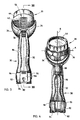
- Fig. 4 is a perspective view showing the bottom of the flashlight of the present invention;
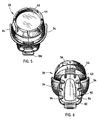
- Fig. 5 is a perspective view showing the front of the flashlight of the present invention;
- Fig. 6 is a perspective view showing the rear of the flashlight of the present invention;
- Fig. 7 is a cross-sectional view taken along line VII-VII of the flashlight shown in Fig. 3; and
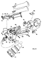
- Fig. 8 is an exploded assembly view of the flashlight of the present invention.
- Reference will now be made in detail to the preferred embodiment of the invention, examples of which are illustrated in the accompanying drawings. Wherever possible, the same reference numerals will be used throughout the drawings to refer to the same or like parts.
- For purposes of description herein, the terms "upper," "lower," "right," "left," "rear," "front," "vertical," "horizontal," "top," "bottom," and derivatives thereof shall relate to the invention as viewed by a person holding the flashlight in a generally horizontal position with the light beam emitted from the front of the flashlight in a forward direction. However, it is to be understood that the invention may assume various alternative orientations, except where expressly specified to the contrary. It is also to be understood that the specific device illustrated in the attached drawings and described in the following specification is simply an exemplary embodiment of the inventive concepts defined in the appended claims. Hence, specific dimensions, proportions, and other physical characteristics relating to the embodiment disclosed herein are not to be considered as limiting, unless the claims expressly state otherwise.
- A
flashlight 10 constnicted in accordance with the present invention is generally shown in Figs. 1-6. Referring to Fig. 1, flashing 10 includes aflashlight head 20 and abody 30. Body 30 includes ahousing 32 that defines an interior battery compartment in which batteries may be stored.Body 30 further includes a pair ofarms 34 extending from a front end ofhousing 32.Flashlight head 20 is mounted between opposing ends ofarms 34, such thatflashlight head 20 may be pivoted relative tobody 30.Body 30 further includes athumb wheel 36 rotatably mounted inhousing 32 and extending partially throughhousing 32 to engageflashlight head 20, such thatflashlight head 20 pivots relative tobody 30 asthumb wheel 36 is rotated. -
Flashlight head 20 serves as a housing for alight bulb 40 and includes arear housing portion 42 having a generally round or spherical rear surface.Flashlight head 20 further includes ashroud 44, alens 46, areflector 48, and a lens bulb holder 50 (see Fig. 7). As best shown in Figs. 1, 7, and 8, a plurality ofparallel grooves 52 are formed in the rear surface ofrear housing 42 so as to define a plurality ofridges 54 that, together withgrooves 52, definegear teeth 56 along a central track on the rear offlashlight head 20. -
Thumb wheel 36 also includes a plurality ofgear teeth 58 defined by a plurality ofridges 60 andrecesses 62 along the perimeter ofthumb wheel 36. As best shown in Fig. 7,gear teeth 58 ofthumb wheel 36 extend through anaperture 64 in the front end ofhousing 32 so as to engage an intermesh withgear teeth 56 on the back offlashlight head 20.Thumb wheel 36 further extends through anaperture 66 in the top surface ofbody housing 32 so as to allow a person to rotatethumb wheel 36 with their thumb or another finger. Thus, asthumb wheel 36 is rotated,flashlight head 20 is caused to pivot relative tobody 30. - As shown in Fig. 8,
thumb wheel 36 is mounted withinbody 30 by means of anaxle 70 that extends through the central axis ofthumb wheel 36 and is received by ahub 72 that is molded in each of twoportions housing 30. - As shown in Figs. 7 a detent 69 may be mounted within
housing 32 forengaging gear teeth 58 onthumb wheel 36. Detent 69 is provided to preventthumb wheel 36 from rotating and hence preventflashlight head 20 from pivoting as the result of vibration or the weight offlashlight head 20 preventing a user from rotatingthumb wheel 36. Thus,flashlight head 20 may be prevented from pivoting when a person does not intendflashlight head 20 to pivot. To accomplish this goal, detent 69 has a rounded surface that engages therecesses 62 inthumb wheel 36. Detent 69 may be mounted around apin 71 and may be made of a resilient material so as to be biased againstthumb wheel 36, and yet be flexible enough to snap back into position into eachrecess 62 asthumb wheel 36 is rotated. -
Flashlight head 20 is secured tobody 30 by means of a pair of pivot pins 74 that extend throughapertures 76 formed through opposing ends ofarms 34 and intoapertures 78 formed on opposite sides ofrear housing 42.Lock washers 80 may be utilized to hold pivot pins 74 in place. Preferably,pivot pin 74 andapertures 76 include a tongue-and-groove configuration so as to preventpin 74 from rotating relative toarms 34. In this manner, the electrical connections required between the batteries, switch, andlight bulb 40 may be run through the interior ofarms 34 and through an aperture provided in the central portion ofpin 74. As is apparent from the drawing figures, pivot pins 74 are aligned along a common axis A about whichflashlight head 20 pivots. This axis is generally perpendicular to a central axis B ofbody 30. As best illustrated in Fig. 2,arms 34 extend from the front end ofbody 30 at an angle, such that pivot axis A extending betweenpins 74 does not intersect or lie in the same plane as central axis B ofbody 30. The significance of such an inclination ofarms 30 is that when the flashlight is set upright on its rear end on the top of a worksurface or table,flashlight head 20 may be pivoted so as to direct light downward onto the worksurface in an area directly adjacent the area upon which the flashlight rest without any component of the flashlight blocking the light that is to be directed downward onto the worksurface. - As used and described herein, the "central axis" of
body 30 is an axis that extends vertically upward and perpendicular to arear surface 82 ofbody 30 upon which the flashlight would rest when set upright on a worksurface. As shown in Fig. 4, central axis B lies in a plane that is a plane of symmetry in the flashlight when viewed from the top or bottom of the flashlight. When viewed from a side of the flashlight (see Fig. 2), central axis B is located in a position that is on average halfway between thetop surface 84 and thebottom surface 86 ofbody 30 in a region ofbody 30 where a person would normally grasp and hold theflashlight 10. - To allow a person to readily turn the flashlight on and off using their forefinger without having to change their grip on the flashlight, an on/off
switch 88 is provided through anaperture 90 provided in thebottom surface 86 offlashlight body 30 in a trigger-like fashion and on an opposite side ofbody 30 thanthumb wheel 36. As apparent from the drawing figures,body 30 is not merely cylindrical in shape, but rather is contoured similar to a pistol grip to ergonomically fit in a person's hand while allowing easy manipulation of the on/off trigger switch. This arrangement allows a person to turn the flashlight on and off with their forefinger while pivotingflashlight head 20 usingthumb wheel 36 without requiring the person to change their grip on the flashlight or use their other hand. Such a configuration is a great convenience to people who have to carry other items in their other hand while using a flashlight. -
Body 30 may further include arear base cap 92 having a plurality offeet 94 that provide a stable resting surface for supporting the flashlight when placed in an upright position onrear surface 82.Rear base 92 may be selectively removed by depressing twolatch buttons 96 provided on opposite sides ofrear base 92. By removingrear base 92, one may gain access to the battery compartment withinbody 30 and hence install or replace batteries 98 (see Fig. 7).Batteries 98 may be housed in acartridge 100 that may be slid into and out of the battery compartment.Base 92 may also be provided so as to be slightly larger than the gripping portion ofbody 30 to enable a more secure grip on the flashlight, to provide a wider, more stable base, and to provide acompartment 102 in which aspare flashlight bulb 104 maybe contained. -
Body 30 may also include abelt clip 106 that is resiliently attached torear base 92 to allow a person to clip and carry the flashlight on their belt or on any other article of clothing or to clip or hang the flashlight on a wall or other article or to suspend the flashlight from a rope or a strap. - The above description is considered that of the preferred embodiment only. Modifications of the invention will occur to those skilled in the art and to those who make or use the invention. Therefore, it is understood that the embodiment shown in the drawings and described above is merely for illustrative purposes and not intended to limit the scope of the invention, which is defined by the following claims as interpreted according to the principles of patent law, including the doctrine of equivalents.
Claims (13)
- A flashlight (10) comprising:- a flashlight body (30);- a flashlight head (20) for accommodating a light source, said head (20) being mounted on said body (30) so as to be rotatable relative to said body (30);wherein the flashlight body (30) includes a housing (32) that defines a battery compartment and a pair of arms (34) extending from a front end of said housing (32) for mounting the flashlight head (20) between opposing ends of the arms such that the flashlight head (20) is pivoted relative to the body (30), characterised in that it further comprises- a thumb wheel (36) mounted on said body (30) so as to be rotatable relative to said body (30), said thumb wheel (36) being configured to engage said head (20) such that, on rotation of said thumb wheel (36) relative to said body (30), said thumb wheel (36) causes said head (20) to rotate relative to said body (30).
- The flashlight (10) as defined in claim 1 wherein each arm (34) includes a pivot pin (74) at said end of that arm (34), said pivot pins (74) of said arms (34) extending towards each other along a common central pin axis (A), said head (20) being mounted to said pins (74) so as to be rotatable about said pin axis (A).
- The flashlight (10) as defined in claim 1 including a light source in the form of light bulb (40) mounted in said head (20).
- The flashlight (10) as defined in claim 1 wherein said head (20) has a rounded surface disposed to engage said thumb wheel (36).
- The flashlight (10) as defined in claim 1 wherein said thumb wheel (36) is mounted to said body (30) within said housing (32), and projects outside of said housing (32) to engage said head (20).
- The flashlight (10) as defined in claim 5 wherein said thumb wheel (36) projects outside of said housing (32) through a side of said housing (32) and through an end of said housing (32).
- The flashlight (10) as defined in any of said preceding claims wherein said thumb wheel (36) includes a plurality of gear teeth (58) and said head (20) includes a plurality of parallel grooves (52) for engaging said gear teeth (58).
- The flashlight (10) as defined in claim 7 including a detent (69) disposed within said body (30) for releasably engaging said gear teeth (58).
- The flashlight (10) as defined in claim 2 wherein said housing (32) is elongate.
- The flashlight (10) as defined in claim 2 wherein said housing (32) has a central housing axis (B), said arms (34) extending from said housing (32) at an angle which is inclined from said housing axis (B) such that said housing axis (B) does not intersect said pin axis (A).
- The flashlight (10) as defined in claim 9 or claim 10 wherein said housing (32) is contoured to fit a palm of a person's hand.
- The flashlight (10) as defined in claim 1 including a switch (88) mounted to said body (30).
- The flashlight (10) as defined in claim 5 including a switch (88) mounted to said body (30) within said housing (32), wherein said thumb wheel (36) projects outside said housing (32) through a side of said housing (32), and said switch (88) projects through an opposite side of said housing (32) such that said switch (88) may be depressed by forefinger of a person's hand while said thumb wheel (36) is being rotated by a thumb of that hand.
Applications Claiming Priority (3)
| Application Number | Priority Date | Filing Date | Title |
|---|---|---|---|
| US15892899P | 1999-10-12 | 1999-10-12 | |
| US158928P | 1999-10-12 | ||
| PCT/AU2000/001231 WO2001027523A1 (en) | 1999-10-12 | 2000-10-11 | Flashlight having a pivoting head |
Publications (3)
| Publication Number | Publication Date |
|---|---|
| EP1222426A1 EP1222426A1 (en) | 2002-07-17 |
| EP1222426A4 EP1222426A4 (en) | 2003-07-23 |
| EP1222426B1 true EP1222426B1 (en) | 2006-05-31 |
Family
ID=22570317
Family Applications (1)
| Application Number | Title | Priority Date | Filing Date |
|---|---|---|---|
| EP00969095A Expired - Lifetime EP1222426B1 (en) | 1999-10-12 | 2000-10-11 | Flashlight having a pivoting head |
Country Status (7)
| Country | Link |
|---|---|
| US (1) | US6457841B1 (en) |
| EP (1) | EP1222426B1 (en) |
| CN (1) | CN1164888C (en) |
| AT (1) | ATE328239T1 (en) |
| AU (1) | AU767594B2 (en) |
| DE (1) | DE60028398T2 (en) |
| WO (1) | WO2001027523A1 (en) |
Families Citing this family (58)
| Publication number | Priority date | Publication date | Assignee | Title |
|---|---|---|---|---|
| US6769787B2 (en) * | 2000-10-11 | 2004-08-03 | Eveready Battery Company, Inc. | Flashlight |
| US7357526B2 (en) * | 2003-08-22 | 2008-04-15 | Milwaukee Electric Tool Corporation | Power tool and accessory |
| US20050064761A1 (en) * | 2003-09-23 | 2005-03-24 | Spx Corporation | Induction heater coupling device and method |
| US7188969B2 (en) * | 2003-09-30 | 2007-03-13 | Uke Alan K | Emergency flashlight |
| US6913370B2 (en) * | 2003-10-02 | 2005-07-05 | Great Neck Saw Manufacturers, Inc. | Flashlight |
| USD499826S1 (en) | 2003-10-02 | 2004-12-14 | Great Neck Saw Manufacturers, Inc. | Flashlight |
| US6913371B2 (en) * | 2003-10-14 | 2005-07-05 | Great Neck Saw Manufacturers, Inc. | Swivel flashlight |
| USD518213S1 (en) | 2003-10-14 | 2006-03-28 | Great Neck Saw Manufacturers, Inc. | Swivel flashlight |
| US6984054B2 (en) * | 2004-01-23 | 2006-01-10 | Li-Chun Lai | Articulated portable lamp fixture |
| USD511392S1 (en) | 2004-02-17 | 2005-11-08 | Vector Products, Inc. | Spotlight |
| USD524957S1 (en) | 2004-09-03 | 2006-07-11 | Milwaukee Electric Tool Company | Light |
| US7557536B2 (en) * | 2004-11-07 | 2009-07-07 | Milwaukee Electric Tool Corporation | Light |
| US7290898B2 (en) * | 2005-03-31 | 2007-11-06 | Biz Research Inc. | Portable and mobile illumination and detection |
| DE102005034600A1 (en) * | 2005-07-25 | 2007-02-01 | Robert Bosch Gmbh | lighting device |
| US7448779B2 (en) * | 2005-08-24 | 2008-11-11 | Osram Sylvania Inc. | Miniature portable lamp with swing arm |
| US7477909B2 (en) * | 2005-10-31 | 2009-01-13 | Nuance Communications, Inc. | System and method for conducting a search using a wireless mobile device |
| US8384340B2 (en) | 2007-06-26 | 2013-02-26 | The Coleman Company, Inc. | Electrical appliance that utilizes multiple power sources |
| US7815337B2 (en) * | 2007-11-16 | 2010-10-19 | Grossman Victor A | Flexible battery container and method of use |
| US7850329B2 (en) * | 2008-05-06 | 2010-12-14 | Blackbeam, Llc | Flashlight with integrated clamp handle |
| US8348454B2 (en) * | 2008-05-06 | 2013-01-08 | Blackbeam Llc | Flashlight with integrated clamp handle |
| US9068705B1 (en) * | 2008-10-07 | 2015-06-30 | Robert L. Carter | 9-volt battery mounted flashlight |
| US8328398B2 (en) * | 2009-01-20 | 2012-12-11 | Gary Van Deursen | Multi-leg rotatable head flashlight |
| US8142045B2 (en) * | 2009-05-04 | 2012-03-27 | Jason Peak | Utility light with articulating mounting legs adapted with suction cup fasteners |
| US8545066B2 (en) | 2009-12-01 | 2013-10-01 | Ullman Devices Corporation | Rotating LED light on a magnetic base |
| US8172436B2 (en) * | 2009-12-01 | 2012-05-08 | Ullman Devices Corporation | Rotating LED light on a magnetic base |
| USD685510S1 (en) | 2011-09-02 | 2013-07-02 | Blackbeam Llc | Flashlight |
| CN102623118B (en) * | 2012-04-10 | 2014-07-16 | 中国航空无线电电子研究所 | Thumb wheel device capable of preventing dialing wheel from dropping |
| US9194547B2 (en) | 2012-07-09 | 2015-11-24 | Blackbeam Llc | Flashlight with integrated clip in handle |
| US9115878B2 (en) | 2012-11-08 | 2015-08-25 | Blackbeam Llc | Spotlight with clamp |
| CN103062633B (en) | 2013-01-14 | 2015-03-25 | 阳江纳谷科技有限公司 | wearable headlamp |
| US9416929B2 (en) * | 2013-09-10 | 2016-08-16 | Mathew Inskeep | Rotary head flashlight headlamp |
| WO2015135220A1 (en) * | 2014-03-14 | 2015-09-17 | Black & Decker Inc | Portable lighting apparatus |
| US10274177B2 (en) | 2014-05-23 | 2019-04-30 | Hubbell Incorpoated | Luminaire with adjustable lamp modules |
| US10107484B2 (en) * | 2014-10-24 | 2018-10-23 | Jennifer Moyers | Lawn mower light |
| CN204300999U (en) * | 2014-11-10 | 2015-04-29 | 李金通 | A kind of portable lamp |
| CN104534294A (en) * | 2014-12-24 | 2015-04-22 | 林军 | Illumination lamp with rotatable lamp cap |
| US9638379B2 (en) * | 2015-03-11 | 2017-05-02 | Shanghai Easy—Use Tools Enterprise Co., Ltd. | Work lamp with magnetic tray and tools |
| CA2930317C (en) | 2015-05-18 | 2021-10-26 | Ac (Macao Commercial Offshore) Limited | Flashlight |
| USD809169S1 (en) | 2016-05-10 | 2018-01-30 | Promier Products, Inc. | Pen light with knurled segments |
| USD878650S1 (en) | 2016-06-21 | 2020-03-17 | Promier Products Inc. | Flashlight |
| USD833050S1 (en) | 2016-10-10 | 2018-11-06 | Alliance Sports Group, L.P. | Flashlight |
| KR200487269Y1 (en) * | 2016-10-21 | 2018-10-04 | 박용주 | Installed in various forms and the possible use lanterns |
| US10704250B2 (en) | 2016-10-28 | 2020-07-07 | Milwaukee Electric Tool Corporation | Sewer cleaning machine |
| JP6830196B2 (en) | 2017-03-31 | 2021-02-17 | パナソニックIpマネジメント株式会社 | lighting equipment |
| EP3649396B1 (en) | 2017-07-06 | 2022-05-11 | Schumacher Electric Corp. | Flashlight |
| USD859715S1 (en) | 2017-09-28 | 2019-09-10 | Coast Cutlery Co. | Tiltable work light |
| US20190120469A1 (en) * | 2017-10-24 | 2019-04-25 | Coast Cutlery Co. | Tiltable work light |
| US10451264B2 (en) * | 2018-03-20 | 2019-10-22 | Tempo Industries, Llc | Water resistant LED light fixtures |
| US11505229B2 (en) | 2018-04-13 | 2022-11-22 | Milwaukee Electric Tool Corporation | Tool support |
| USD906559S1 (en) | 2018-04-26 | 2020-12-29 | Milwaukee Electric Tool Corporation | Light |
| US11098858B2 (en) | 2018-04-26 | 2021-08-24 | Milwaukee Electric Tool Corporation | Portable light having a pivotable light head |
| USD923838S1 (en) * | 2018-11-08 | 2021-06-29 | Ningbo Futai Electric Limited | Swivel light |
| US12409478B2 (en) | 2019-06-10 | 2025-09-09 | Milwaukee Electric Tool Corporation | Transportable machine including a track system |
| US11215330B1 (en) * | 2020-09-09 | 2022-01-04 | First-Light Usa, Llc | Power routing for illumination device |
| CN220601388U (en) * | 2020-12-04 | 2024-03-15 | 米沃奇电动工具公司 | headlamp |
| WO2022155214A1 (en) | 2021-01-12 | 2022-07-21 | Milwaukee Electric Tool Corporation | Portable light, such as a stick light |
| EP4170225A1 (en) | 2021-07-13 | 2023-04-26 | Techtronic Cordless GP | Multi-mount system for light |
| USD1092814S1 (en) | 2022-01-12 | 2025-09-09 | Milwaukee Electric Tool Corporation | Portable light |
Family Cites Families (35)
| Publication number | Priority date | Publication date | Assignee | Title |
|---|---|---|---|---|
| GB561292A (en) * | 1941-02-08 | 1944-05-15 | Henry Hyman | Improvements in portable electric flashlights |
| DE3011096A1 (en) | 1980-03-22 | 1981-10-15 | Robert Bosch Gmbh, 7000 Stuttgart | BATTERY LAMP, IN PARTICULAR HAND LAMP, WITH INTEGRATED WARNING FLASHING DEVICE |
| JPS56160701A (en) | 1980-05-14 | 1981-12-10 | Sanyo Electric Co | Portable lamp |
| GB2123940B (en) | 1982-06-29 | 1986-02-12 | Duracell Int | Flashlight |
| US4428033A (en) | 1982-07-14 | 1984-01-24 | Mcbride Scott T | Flashlight having test leads and a second, remote, magnetically attachable rotatable lamp |
| US4447863A (en) * | 1983-01-24 | 1984-05-08 | Pittway Corp | Hand-held light with swivel head |
| US4533982A (en) | 1984-10-22 | 1985-08-06 | Kozar John J | Flashlight with swivelling head |
| US4654764A (en) | 1985-10-15 | 1987-03-31 | Hsiao Meng Chang | Rotary structure for the head portion of an illumination light |
| US4777572A (en) | 1986-11-25 | 1988-10-11 | Emilio Ambasz | Flashlight with adjustable lamp housing |
| DE3829337A1 (en) | 1987-04-02 | 1990-03-08 | Jaroslav Bech | Contactless connection and automatic adjustment of the foldable parts of a luminaire, as well as switching them on and off without sliding contacts |
| US5012394A (en) | 1988-11-15 | 1991-04-30 | Woodward John G | Hand portable light with extendable lamp housing |
| GB2238861B (en) | 1989-12-05 | 1993-03-10 | Fatia Ind Co Ltd | Portable battery operated lighting device |
| US5097399A (en) | 1990-08-10 | 1992-03-17 | Gammache Richard J | Flashlight with swivel head |
| US5043854A (en) | 1990-08-10 | 1991-08-27 | Gammache Richard J | Flashlight with swivel head |
| US5161095A (en) | 1990-08-10 | 1992-11-03 | Gammache Richard J | Flashlight with swivel head and rotary switch |
| USD332320S (en) | 1991-02-06 | 1993-01-05 | Gammache Richard J | Flashlight with swivel head |
| ES1021612Y (en) | 1992-06-08 | 1993-07-01 | M. Ros, S.A. | RECHARGEABLE EMERGENCY FLASHLIGHT FOR CARS AND THE LIKE. |
| US5239451A (en) | 1992-08-31 | 1993-08-24 | Ahrens-Fox Fire Engine Company | Flashlight for firefighting and other specialized uses |
| US5410457A (en) | 1993-07-02 | 1995-04-25 | Parker; David H. | Small-sized versatile-use flashlight |
| GB2285855B (en) | 1994-01-24 | 1997-08-20 | John Mfg Ltd | A dual-purpose torch for projecting ordinary and hazard warning light |
| US5541822A (en) * | 1994-02-25 | 1996-07-30 | The Coleman Company, Inc. | Flashlight with pivoting head |
| US5558430A (en) | 1994-12-09 | 1996-09-24 | Phorm Concept And Design, Inc. | Dual beam flashlight |
| USD375811S (en) | 1995-04-11 | 1996-11-19 | Gsl Rechargeable Products, Ltd. | Flashlight with pivoting head |
| US5684452A (en) * | 1995-06-12 | 1997-11-04 | Wang; Shiunn-Terny | Multi-purposes warning device |
| US5853241A (en) * | 1995-10-16 | 1998-12-29 | Streamlight, Inc. | Convertible flashlight |
| US5605394A (en) * | 1996-06-19 | 1997-02-25 | Regitar Power Co., Ltd. | Flashlight |
| USD406372S (en) * | 1996-08-09 | 1999-03-02 | Black & Decker Inc. | Pivot head flashlight |
| US5871272A (en) | 1997-01-28 | 1999-02-16 | Streamlight, Incorporated | Flashlight with rotatable lamp head |
| JPH10228801A (en) | 1997-02-12 | 1998-08-25 | Seizo Tanabe | Lift-up lantern |
| US5988828A (en) * | 1997-07-18 | 1999-11-23 | Milwaukee Electric Tool Corporation | Portable light incorporating a multi-position hook |
| USD404839S (en) * | 1998-06-16 | 1999-01-26 | Rayovac Corporation | Flashlight |
| US5993022A (en) * | 1998-07-08 | 1999-11-30 | Rayovac Corporation | Multi-pivot flashlight |
| USD413994S (en) * | 1998-08-27 | 1999-09-14 | Porter-Cable Corporation | Battery powered flashlight |
| GB2341408A (en) | 1998-09-11 | 2000-03-15 | Wang Shiunn Terny | Portable hazard-warning device |
| US6186638B1 (en) * | 1999-10-04 | 2001-02-13 | Awi Acquisition Company | Wrench which includes flashlight |
-
2000
- 2000-10-11 AT AT00969095T patent/ATE328239T1/en not_active IP Right Cessation
- 2000-10-11 CN CNB008139369A patent/CN1164888C/en not_active Expired - Fee Related
- 2000-10-11 AU AU78922/00A patent/AU767594B2/en not_active Ceased
- 2000-10-11 DE DE60028398T patent/DE60028398T2/en not_active Expired - Fee Related
- 2000-10-11 WO PCT/AU2000/001231 patent/WO2001027523A1/en not_active Ceased
- 2000-10-11 EP EP00969095A patent/EP1222426B1/en not_active Expired - Lifetime
- 2000-10-12 US US09/689,064 patent/US6457841B1/en not_active Expired - Lifetime
Also Published As
| Publication number | Publication date |
|---|---|
| WO2001027523A1 (en) | 2001-04-19 |
| CN1378630A (en) | 2002-11-06 |
| DE60028398T2 (en) | 2006-11-02 |
| AU767594B2 (en) | 2003-11-20 |
| EP1222426A1 (en) | 2002-07-17 |
| AU7892200A (en) | 2001-04-23 |
| US6457841B1 (en) | 2002-10-01 |
| DE60028398D1 (en) | 2006-07-06 |
| CN1164888C (en) | 2004-09-01 |
| EP1222426A4 (en) | 2003-07-23 |
| ATE328239T1 (en) | 2006-06-15 |
Similar Documents
| Publication | Publication Date | Title |
|---|---|---|
| US6457841B1 (en) | Flashlight having a pivoting head | |
| US5988828A (en) | Portable light incorporating a multi-position hook | |
| US4447863A (en) | Hand-held light with swivel head | |
| US6575587B2 (en) | Light with clamp that fits into a headband | |
| US6953259B2 (en) | Adjustable flashlight case | |
| US6619813B1 (en) | Multi-purpose LED light | |
| US5355147A (en) | Ergonomic computer mouse | |
| US7568812B1 (en) | Personal headlamp | |
| US7401941B2 (en) | Flashlight | |
| US9194547B2 (en) | Flashlight with integrated clip in handle | |
| US5816684A (en) | Positionable flashlight and holder | |
| US4654764A (en) | Rotary structure for the head portion of an illumination light | |
| JPH0357101A (en) | Portable light | |
| US7066615B2 (en) | Light retainer | |
| AU2004200761B2 (en) | Swivel flashlight | |
| EP0856120A4 (en) | Convertible flashlight | |
| US20030227773A1 (en) | Light device for attaching onto various objects | |
| CA2216502A1 (en) | Portable light | |
| US5142467A (en) | Hand held spotlight with tripod handle | |
| US3893144A (en) | Pistol grip for a camera | |
| JP2013518392A (en) | Folding spotlight | |
| US4414612A (en) | Hand-held light with means for controlling beam width | |
| US7172311B2 (en) | Flashlight devices and accessories | |
| US7771076B1 (en) | Hand held light emitting device | |
| JP6703402B2 (en) | Neck hanging light |
Legal Events
| Date | Code | Title | Description |
|---|---|---|---|
| PUAI | Public reference made under article 153(3) epc to a published international application that has entered the european phase |
Free format text: ORIGINAL CODE: 0009012 |
|
| 17P | Request for examination filed |
Effective date: 20020412 |
|
| AK | Designated contracting states |
Kind code of ref document: A1 Designated state(s): AT BE CH CY DE DK ES FI FR GB GR IE IT LI LU MC NL PT SE |
|
| AX | Request for extension of the european patent |
Free format text: AL;LT;LV;MK;RO;SI |
|
| A4 | Supplementary search report drawn up and despatched |
Effective date: 20030612 |
|
| 17Q | First examination report despatched |
Effective date: 20040113 |
|
| GRAP | Despatch of communication of intention to grant a patent |
Free format text: ORIGINAL CODE: EPIDOSNIGR1 |
|
| GRAS | Grant fee paid |
Free format text: ORIGINAL CODE: EPIDOSNIGR3 |
|
| GRAA | (expected) grant |
Free format text: ORIGINAL CODE: 0009210 |
|
| AK | Designated contracting states |
Kind code of ref document: B1 Designated state(s): AT BE CH CY DE DK ES FI FR GB GR IE IT LI LU MC NL PT SE |
|
| PG25 | Lapsed in a contracting state [announced via postgrant information from national office to epo] |
Ref country code: IT Free format text: LAPSE BECAUSE OF FAILURE TO SUBMIT A TRANSLATION OF THE DESCRIPTION OR TO PAY THE FEE WITHIN THE PRE;WARNING: LAPSES OF ITALIAN PATENTS WITH EFFECTIVE DATE BEFORE 2007 MAY HAVE OCCURRED AT ANY TIME BEFORE 2007. THE CORRECT EFFECTIVE DATE MAY BE DIFFERENT FROM THE ONE RECORDED.SCRIBED TIME-LIMIT Effective date: 20060531 Ref country code: CH Free format text: LAPSE BECAUSE OF FAILURE TO SUBMIT A TRANSLATION OF THE DESCRIPTION OR TO PAY THE FEE WITHIN THE PRESCRIBED TIME-LIMIT Effective date: 20060531 Ref country code: AT Free format text: LAPSE BECAUSE OF FAILURE TO SUBMIT A TRANSLATION OF THE DESCRIPTION OR TO PAY THE FEE WITHIN THE PRESCRIBED TIME-LIMIT Effective date: 20060531 Ref country code: NL Free format text: LAPSE BECAUSE OF FAILURE TO SUBMIT A TRANSLATION OF THE DESCRIPTION OR TO PAY THE FEE WITHIN THE PRESCRIBED TIME-LIMIT Effective date: 20060531 Ref country code: LI Free format text: LAPSE BECAUSE OF FAILURE TO SUBMIT A TRANSLATION OF THE DESCRIPTION OR TO PAY THE FEE WITHIN THE PRESCRIBED TIME-LIMIT Effective date: 20060531 Ref country code: FI Free format text: LAPSE BECAUSE OF FAILURE TO SUBMIT A TRANSLATION OF THE DESCRIPTION OR TO PAY THE FEE WITHIN THE PRESCRIBED TIME-LIMIT Effective date: 20060531 Ref country code: BE Free format text: LAPSE BECAUSE OF FAILURE TO SUBMIT A TRANSLATION OF THE DESCRIPTION OR TO PAY THE FEE WITHIN THE PRESCRIBED TIME-LIMIT Effective date: 20060531 |
|
| REG | Reference to a national code |
Ref country code: GB Ref legal event code: FG4D Ref country code: CH Ref legal event code: EP |
|
| REG | Reference to a national code |
Ref country code: IE Ref legal event code: FG4D |
|
| REF | Corresponds to: |
Ref document number: 60028398 Country of ref document: DE Date of ref document: 20060706 Kind code of ref document: P |
|
| PG25 | Lapsed in a contracting state [announced via postgrant information from national office to epo] |
Ref country code: DK Free format text: LAPSE BECAUSE OF FAILURE TO SUBMIT A TRANSLATION OF THE DESCRIPTION OR TO PAY THE FEE WITHIN THE PRESCRIBED TIME-LIMIT Effective date: 20060831 Ref country code: SE Free format text: LAPSE BECAUSE OF FAILURE TO SUBMIT A TRANSLATION OF THE DESCRIPTION OR TO PAY THE FEE WITHIN THE PRESCRIBED TIME-LIMIT Effective date: 20060831 |
|
| PG25 | Lapsed in a contracting state [announced via postgrant information from national office to epo] |
Ref country code: ES Free format text: LAPSE BECAUSE OF FAILURE TO SUBMIT A TRANSLATION OF THE DESCRIPTION OR TO PAY THE FEE WITHIN THE PRESCRIBED TIME-LIMIT Effective date: 20060911 |
|
| PGFP | Annual fee paid to national office [announced via postgrant information from national office to epo] |
Ref country code: MC Payment date: 20060920 Year of fee payment: 7 |
|
| PGFP | Annual fee paid to national office [announced via postgrant information from national office to epo] |
Ref country code: IE Payment date: 20061026 Year of fee payment: 7 |
|
| PG25 | Lapsed in a contracting state [announced via postgrant information from national office to epo] |
Ref country code: PT Free format text: LAPSE BECAUSE OF FAILURE TO SUBMIT A TRANSLATION OF THE DESCRIPTION OR TO PAY THE FEE WITHIN THE PRESCRIBED TIME-LIMIT Effective date: 20061031 |
|
| NLV1 | Nl: lapsed or annulled due to failure to fulfill the requirements of art. 29p and 29m of the patents act | ||
| PGFP | Annual fee paid to national office [announced via postgrant information from national office to epo] |
Ref country code: LU Payment date: 20061107 Year of fee payment: 7 |
|
| PGFP | Annual fee paid to national office [announced via postgrant information from national office to epo] |
Ref country code: DE Payment date: 20061130 Year of fee payment: 7 |
|
| ET | Fr: translation filed | ||
| REG | Reference to a national code |
Ref country code: CH Ref legal event code: PL |
|
| PLBE | No opposition filed within time limit |
Free format text: ORIGINAL CODE: 0009261 |
|
| STAA | Information on the status of an ep patent application or granted ep patent |
Free format text: STATUS: NO OPPOSITION FILED WITHIN TIME LIMIT |
|
| 26N | No opposition filed |
Effective date: 20070301 |
|
| PG25 | Lapsed in a contracting state [announced via postgrant information from national office to epo] |
Ref country code: GR Free format text: LAPSE BECAUSE OF FAILURE TO SUBMIT A TRANSLATION OF THE DESCRIPTION OR TO PAY THE FEE WITHIN THE PRESCRIBED TIME-LIMIT Effective date: 20060901 |
|
| PG25 | Lapsed in a contracting state [announced via postgrant information from national office to epo] |
Ref country code: MC Free format text: LAPSE BECAUSE OF NON-PAYMENT OF DUE FEES Effective date: 20071031 |
|
| PG25 | Lapsed in a contracting state [announced via postgrant information from national office to epo] |
Ref country code: DE Free format text: LAPSE BECAUSE OF NON-PAYMENT OF DUE FEES Effective date: 20080501 |
|
| PG25 | Lapsed in a contracting state [announced via postgrant information from national office to epo] |
Ref country code: IE Free format text: LAPSE BECAUSE OF NON-PAYMENT OF DUE FEES Effective date: 20071011 |
|
| PG25 | Lapsed in a contracting state [announced via postgrant information from national office to epo] |
Ref country code: CY Free format text: LAPSE BECAUSE OF FAILURE TO SUBMIT A TRANSLATION OF THE DESCRIPTION OR TO PAY THE FEE WITHIN THE PRESCRIBED TIME-LIMIT Effective date: 20060531 |
|
| PG25 | Lapsed in a contracting state [announced via postgrant information from national office to epo] |
Ref country code: LU Free format text: LAPSE BECAUSE OF NON-PAYMENT OF DUE FEES Effective date: 20071011 |
|
| PGFP | Annual fee paid to national office [announced via postgrant information from national office to epo] |
Ref country code: GB Payment date: 20091026 Year of fee payment: 10 Ref country code: FR Payment date: 20091029 Year of fee payment: 10 |
|
| GBPC | Gb: european patent ceased through non-payment of renewal fee |
Effective date: 20101011 |
|
| PG25 | Lapsed in a contracting state [announced via postgrant information from national office to epo] |
Ref country code: FR Free format text: LAPSE BECAUSE OF NON-PAYMENT OF DUE FEES Effective date: 20101102 |
|
| REG | Reference to a national code |
Ref country code: FR Ref legal event code: ST Effective date: 20110630 |
|
| PG25 | Lapsed in a contracting state [announced via postgrant information from national office to epo] |
Ref country code: GB Free format text: LAPSE BECAUSE OF NON-PAYMENT OF DUE FEES Effective date: 20101011 |