EP1221777A1 - Method and apparatus for classifying interference - Google Patents
Method and apparatus for classifying interference Download PDFInfo
- Publication number
- EP1221777A1 EP1221777A1 EP00610133A EP00610133A EP1221777A1 EP 1221777 A1 EP1221777 A1 EP 1221777A1 EP 00610133 A EP00610133 A EP 00610133A EP 00610133 A EP00610133 A EP 00610133A EP 1221777 A1 EP1221777 A1 EP 1221777A1
- Authority
- EP
- European Patent Office
- Prior art keywords
- interference
- mobile communications
- communications terminal
- signal
- signals
- Prior art date
- Legal status (The legal status is an assumption and is not a legal conclusion. Google has not performed a legal analysis and makes no representation as to the accuracy of the status listed.)
- Granted
Links
Images


Classifications
-
- H—ELECTRICITY
- H04—ELECTRIC COMMUNICATION TECHNIQUE
- H04L—TRANSMISSION OF DIGITAL INFORMATION, e.g. TELEGRAPHIC COMMUNICATION
- H04L1/00—Arrangements for detecting or preventing errors in the information received
- H04L1/20—Arrangements for detecting or preventing errors in the information received using signal quality detector
-
- H—ELECTRICITY
- H04—ELECTRIC COMMUNICATION TECHNIQUE
- H04B—TRANSMISSION
- H04B17/00—Monitoring; Testing
- H04B17/30—Monitoring; Testing of propagation channels
- H04B17/309—Measuring or estimating channel quality parameters
- H04B17/345—Interference values
Definitions
- This invention relates to a mobile communications terminal for use in a cellular communications system, comprising an electronic circuit for receiving a wire-less communication signal carrying signal channels having processing means for extracting the signal channels.
- a typical cellular telecommunications system cell is organised about a base-station equipped with multiplexing means for transmitting communication signals carrying signal channels from a wired telephone net onto a radio frequency carrier that is broadcast by an antenna system over an area that the cell is designate to cover.
- a set of individual mobile subscriber stations - i.e. a mobile communications terminal - are each equipped to receive the broadcast frequency carrier and to de-multiplex the specific channel the terminal is intended to receive.
- two-way communication is supported and the mobile communications terminal is adapted to transmit signals to the base-station for subsequent multiplexing and distribution to a wired net or another base-station.
- an assigned radio frequency bandwidth of frequencies is simultaneously shared by multiple subscribers using various multiple access techniques e.g. code division multiple access (CDMA).
- CDMA code division multiple access
- multiple subscribers can be accommodated on a single carrier in which each subscriber is assigned one or multiple codes that is used to carry information.
- a code waveform taken from a set of orthogonal waveforms allows the system to transmit information in separate information channels. These separate information channels can be used to carry individual information to different users and/or enable multiple information streams to one user.
- the interference situation can vary from time to time depending on the location of the mobile communications terminal relative to the base-station, the location of other base-stations, the actual load of the system, and the type of traffic on the communication channels. Furthermore, moving the mobile communications terminal relative to the base-station and movement of other objects affecting the transmission path between the base-station and the mobile communications terminal can affect the interference situation.
- interference can be divided into two groups:
- Inter-cell interference originates from one or more neighbouring base stations.
- the fading of inter-cell interference is uncorrelated with the fading of the communication signal.
- inter-cell interference refers to interference that has an uncorrelated fading or no fading.
- inter-cell interference can be caused by thermal noise etc.
- Intra-cell interference originates from the same base station as the base station communicating with the mobile communications terminal. Intra-cell interference is due to reception of non-orthogonal signals transmitted from the base station (e.g. the synchronisation channel in WCDMA) or due to multi-path propagation of the communication signal).
- One important feature of intra-cell interference is that it travels the same path as the communication signal and thus experience the same fading.
- the type of interference that a communication signal is distorted with at reception by a mobile communication terminal is an important parameter for optimisation of several algorithms in the terminal and in turn for improving the quality of the wire-less communication.
- the prior art involves the problem that a present type of interference affecting performance in the form of transmission capacity and/or quality of a mobile communications terminal is not determined - thereby not making it possible to take the type of interference into account when communicating by means of the mobile communications terminal.
- an object of this invention is to provide a mobile communications terminal for use in a cellular communications system capable of determining a present type of interference.
- the electronic circuit is adapted to classify a type of interference, affecting the communications quality, by evaluating signals selected in the electronic circuit as signals having information for classifying a type of interference in one of at least two predetermined classes of interference.
- Fig. 1 shows a cell-structure in a cellular communications system.
- the cell-structure comprises a number of cells 101 each of them including a base-station 102.
- the base-station 102 is adapted to provide wire-less communication with one - or typically more - mobile communication terminals 106 located within the cell and to provide communication with other base-stations or switching units by means of a wired net.
- the base-stations are located to provide a desired level of communication coverage for wire-less communication over a given geographical area.
- Wire-less communication signals emitted from a base-station with a specified power-level will be damped as a function of the distance to the transmitter.
- propagation of the wire-less communication signals cannot be controlled precisely due to the presence of buildings, different types of landscape features etc. it will be possible in some areas between two base-stations 107 and 108 to detect signals transmitted from both of the base-stations. Such an area is illustrated as the area covered by both of the circles 103 and 104 that indicates a radiation pattern from the base-stations 107 and 108, respectively.
- circuitry is adapted to select one or many out of two or more base-stations capable of providing communication with the base-stations e.g. to select the base-station providing the best communication quality.
- other base-stations still transmits communication signals that can and will interfere with communication signals from a selected base-station thus degrading the communication quality otherwise obtainable from the selected base-station. This is called inter-cell interference.
- Fig. 2 shows a block-diagram of a typical mobile communications terminal. It is shown how signals used for common purposes e.g. demodulation, gain control, etc. in the mobile communications terminal can be detected for the special purpose of classifying interference.
- a wire-less communication signal can be received by an antenna 202 connected to an antenna filter 201 for passing the communication signal and rejecting other signals.
- the output of the antenna filter is connected to a high frequency amplifier 203 that is controlled by an automatic gain control unit 204 to compensate for a varying signal strength of the received communication signal.
- the signal AGC-GAIN is a signal controlling the gain of the amplifier 203. According to the invention, such an AGC-GAIN signal can be selected as a signal having information for classifying interference.
- the output of the amplifier 203 is provided as a first input signal to a mixer 206 via a band-pass filter 205 removing high-frequency noise and low-frequency components i.a. from the automatic gain control unit.
- a second input signal to the mixer 206 is provided by a frequency synthesis unit 211 via a phase-locked loop comprising a controlled oscillator 215, a frequency divider 213, a phase-detector 212, and a band-pass filter 214.
- the communication signal is shifted down in frequency to an intermediate frequency IF.
- the communication signal at the intermediate frequency is, output from the mixer 206, is fed to a demodulator 209 via an intermediate frequency amplifier 207 and a band-pass filter 208 with a pass-band around the intermediate frequency.
- the processor 210 is connected to the demodulator 209 to decode information e.g. voice, V, and data, D, transmitted on the communications channel.
- the processor 210 is adapted to calculate an interference power estimate.
- an interference estimate, INT is calculated based on the variance of received known symbols (so-called pilots) i.e. a test sequence transmitted by the base-station.
- pilots i.e. a test sequence transmitted by the base-station.
- such an interference power estimate can be selected as a signal having information for classifying interference.
- the processor 220 is adapted to calculate a signal S that represents the strength of the communication signal from the base-station the terminal is in communication with.
- the signal S can be measured as the power at the common pilot channel (CPICH).
- CPICH common pilot channel
- the signal S representing the strength of the received communication signal can be monitored and selected as a signal having information for classifying interference.
- the information is encoded in the processor 220 to transmit this information on a communications channel.
- the information is modulated on a intermediate frequency IF by means of a modulator 217.
- the intermediate frequency IF is supplied by a frequency synthesis unit 219 via a band-pass filter 218.
- the modulator 217 is connected to a mixer 216 for up-shifting the signal at the intermediate frequency to a high-frequency carrier.
- the up-shifted signal is supplied to the antenna 202 via a band-pass filter 221, a high-frequency amplifier 222, and an antenna filter 201.
- TPC Transmission-Power-Control
- the processor 220 is adapted to communicate such TPC commands to a base-station in response to a monitoring of a received communication signal.
- the mobile communications terminal can request the base-station to transmit communication signal to the terminal with more power to obtain a sufficient communication quality if the received communication signal is too weak and vice versa.
- such Transmission-Power-Control commands can be selected as a signal having information for classifying interference.
- homodyne receivers can include the above mentioned or other types of signals having information for classifying interference.
- Fig. 3 shows a classifier for determining a type of interference.
- the classifier 301 is connected to receive the signals AGC-GAIN, TPC, INT, and S and adapted to classify an interference affecting at least one of the signals GAIN, TPC, INT, and S as either inter-cell or intra-cell interference.
- the classifier 301 provides two binary signals INTRA and INTER. The binary signals can be used for selecting different algorithms depending on the type of interference determined by classifier.
- the algorithm A1 When intra-cell interference is detected, the algorithm A1 is enabled and when inter-cell interference is detected, the algorithm A2 is enabled.
- the algorithms receives input data via the port IN and provides output data via the port OUT.
- it can be expedient to load an algorithm with different sets of parameters that are selected or calculated in response to the signals from the classifier.
- Inter-cell interference can be considered as stationary white noise since communication signals from base-stations in neighbour cells correlates to a small extend only with communication signals from a selected base-station. Therefore, it is convenient to reconstruct i.e. enhance the quality e.g. by enhancing the signal-to-noise ratio of the communication signal with a filter - providing some type of averaging - that has a relatively large time-constant.
- Intra-cell interference should not be considered as stationary white noise since a communication signal travelling along different paths creates time-shifted and amplitude varying echoes only, thus having a relatively large correlation with each other. This in turn creates an amplitude varying communication signal. Therefore, it is convenient to reconstruct the communication signal with a filter providing some type of averaging over a relatively short time interval, e.g. by means of a moving average filter..
- the algorithms A1 and A2 and the classifier 301 can be embodied as program code for the processor 220 - and/or be embodied directly in an application specific integrated circuit, ASIC.
- the algorithms A1 and A2 can implement two digital low-pass filters e.g. with a relatively high and a relatively low bandwidth.
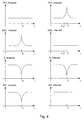
- Fig. 4 shows different variables/signals available in a mobile communications terminal as a function of time t in inter-cell and intra-cell interference situations. These signals include information for classifying i.e. determining a type of interference and may therefore be selected for that purpose. The signals can be detected in the flow-chart shown in fig. 5.
- the TPC signal When intra-cell interference is present, the TPC signal will remain substantially constant over time, the AGC signal will peak in amplitude, and the signal strength, S, and the interference estimate will dip in amplitude.
- the AGC signal and the interference estimate, INT will remain substantially constant over time, the TPC signal will peak in amplitude, and the signal strength, S, will dip in amplitude.
- the signals can be continues analogue signals or discrete digital signals.
- the signals can be sampled over time and two or more samples at different times can be compared such that it is possible to detect the signal characteristics e.g. a peak, a dip, etc.
- Fig. 5 shows a flow-chart for a method of classifying interference.
- the flow-chart illustrates the operation of the classifier 301 in co-operation with the mobile communications terminal in fig. 2.
- step 501 a communication signal from a base-station is received.
- step 502 it is verified whether a test statement TST1 capable of detecting intra-cell interference based on selected signals is true or false. If the test statement TST1 is true it is determined that intra-cell interference is present.
- the mobile communications terminal is controlled to use parameters that are optimal for receiving intra-cell distorted communication signals.
- test statement TST1 it is verified whether a test statement TST2 capable of detecting inter-cell interference based on selected signals is true or false. If the test statement TST2 is true it is determined that inter-cell interference is present. In step 505 the mobile communications terminal is controlled to use parameters that are optimal for receiving inter-cell distorted communication signals.
- TST1 capable of detecting intra-cell interference can be stated in numerous ways, e.g. in the following ways: TST1: a) ABS(INT(T) - INT(T-n)) ⁇ e b) ABS(AGC(T) - AGC(T-n)) ⁇ e
- test statement TST2 capable of detecting inter-cell interference can be stated in numerous ways, e.g. in the following ways: TST2: c) ABS(INT(T) - INT(T-n)) > e d) ABS(TPC(T) - TPC(T-n)) ⁇ e
- Fig. 6 shows a block-diagram of a preferred mobile communications terminal according to the invention wherein the determined interference type is used to improve the interference power estimate.
- the terminal comprises an antenna 601 for receiving a wire-less communication signal that is amplified and converted to a digital signal S(k) in high-frequency amplifier 602.
- S(k) is a sequence of digital samples where k denotes a sample in the sequence.
- the digital signal S(k) is provided to an interference estimator 603 that provides an interference estimate in the form of a sequence of digital samples Î(k). This interference estimate is supplied to a digital low-pass filter 604.
- I FILT (k) ⁇ I FILT (k-1) + (1- ⁇ )Î(k) where Î(k) is input to the filter, I FILT (k) is output from the filter and ⁇ is a filter constant.
- the number of samples the filter is calculating an average over can be approximated as 1/(1- ⁇ ).
- the interference power estimate is calculated by employing much filtering in the estimation of the interference power estimate. This can be carried out by averaging over a relatively large number of samples, e.g. with ⁇ 0,99; thereby the filter has a relatively low band-width. Consequently, the variance of the interference power estimate is reduced. This will improve the interference power estimate since in this situation the interference may appear as almost stationary in time (the signals causing the interference are almost uncorrelated with the communication signal).
- the output signal from the digital filter 604 is supplied to a power control component 605.
- This power control component is arranged to communicate with the base station to control the power level of communication signals transmitted to the mobile terminal.
- the output signal from the digital filter 604 is also supplied to a soft information processor 606 that provides so-called side information in the form of a Maximum Ratio Combining (MRC) signal.
- Side information provides a quality measure of the received wireless signal and can in turn be used as reliability information in a process of decoding symbols in the received signal.
- the soft information processor 606 receives the filtered symbols and split them into a number of branches; in each branch random values are added to the filtered symbols I FILT (k). In each branch a filter is applied. The bandwidth of these filters are adjusted according to the type of interference.
- the filters may be low-pass filters where a relatively low cut-off frequency is selected when intra cell interference is present, and where a relatively high cut-off frequency is selected when inter cell interference is present. Signals provided by each of the branches are added with a weight value that equals the signal-to-noise ratio for each branch and subsequently supplied as the Maximum Ratio Combining signal.
- inter-cell and intra cell-inter interference has been described as two major groups of interference a more precise classification of interference can be used.
- the invention can find application in all fields of mobile wire-less communications systems - e.g. in systems allowing for direct terminal-to-terminal communication without involving a base-station.
Landscapes
- Engineering & Computer Science (AREA)
- Quality & Reliability (AREA)
- Computer Networks & Wireless Communication (AREA)
- Signal Processing (AREA)
- Physics & Mathematics (AREA)
- Electromagnetism (AREA)
- Mobile Radio Communication Systems (AREA)
- Seasonings (AREA)
Abstract
Description
- This invention relates to a mobile communications terminal for use in a cellular communications system, comprising an electronic circuit for receiving a wire-less communication signal carrying signal channels having processing means for extracting the signal channels.
- A typical cellular telecommunications system cell is organised about a base-station equipped with multiplexing means for transmitting communication signals carrying signal channels from a wired telephone net onto a radio frequency carrier that is broadcast by an antenna system over an area that the cell is designate to cover. A set of individual mobile subscriber stations - i.e. a mobile communications terminal - are each equipped to receive the broadcast frequency carrier and to de-multiplex the specific channel the terminal is intended to receive. Typically, two-way communication is supported and the mobile communications terminal is adapted to transmit signals to the base-station for subsequent multiplexing and distribution to a wired net or another base-station.
- In such a wire-less communications system, an assigned radio frequency bandwidth of frequencies is simultaneously shared by multiple subscribers using various multiple access techniques e.g. code division multiple access (CDMA). In CDMA systems multiple subscribers can be accommodated on a single carrier in which each subscriber is assigned one or multiple codes that is used to carry information. A code waveform taken from a set of orthogonal waveforms allows the system to transmit information in separate information channels. These separate information channels can be used to carry individual information to different users and/or enable multiple information streams to one user.
- However, in such systems different types of interference may occur and diminish the communication quality. The interference situation can vary from time to time depending on the location of the mobile communications terminal relative to the base-station, the location of other base-stations, the actual load of the system, and the type of traffic on the communication channels. Furthermore, moving the mobile communications terminal relative to the base-station and movement of other objects affecting the transmission path between the base-station and the mobile communications terminal can affect the interference situation.
- Basically, interference can be divided into two groups:
- 1. inter-cell interference, and
- 2. intra-cell interference.
-
- Inter-cell interference originates from one or more neighbouring base stations. The fading of inter-cell interference is uncorrelated with the fading of the communication signal. In the following, inter-cell interference refers to interference that has an uncorrelated fading or no fading. Thus, inter-cell interference can be caused by thermal noise etc.
- Intra-cell interference originates from the same base station as the base station communicating with the mobile communications terminal. Intra-cell interference is due to reception of non-orthogonal signals transmitted from the base station (e.g. the synchronisation channel in WCDMA) or due to multi-path propagation of the communication signal). One important feature of intra-cell interference is that it travels the same path as the communication signal and thus experience the same fading.
- The type of interference that a communication signal is distorted with at reception by a mobile communication terminal is an important parameter for optimisation of several algorithms in the terminal and in turn for improving the quality of the wire-less communication.
- There exists known methods for classifying interference by means of spectrum estimation techniques. However, these methods are very complex and involves large processing means. The different types of interference may degrade performance of a mobile communications terminal. Thus there is a need for a less complex method that can be implemented in small-sized and/or mobile communication terminals.
- Therefore, the prior art involves the problem that a present type of interference affecting performance in the form of transmission capacity and/or quality of a mobile communications terminal is not determined - thereby not making it possible to take the type of interference into account when communicating by means of the mobile communications terminal.
- Thus an object of this invention is to provide a mobile communications terminal for use in a cellular communications system capable of determining a present type of interference.
- This is achieved when the mobile communications terminal mentioned in the opening paragraph is characterized in that the electronic circuit is adapted to classify a type of interference, affecting the communications quality, by evaluating signals selected in the electronic circuit as signals having information for classifying a type of interference in one of at least two predetermined classes of interference.
- Consequently, it is possible to determine a present type of interference by evaluating internal signals that are present in a standard mobile communications terminal. Thus, it is possible to take the type of interference into account when correcting a received communications signal - thereby providing for a better performance of the mobile communications terminal. Further, only simple means for classifying the type of interference are needed since the signals having information for classifying a present type of interference are already present internally for verifying, adjusting, or demodulating the communication signals.
- The invention will be explained more fully below in connection with a preferred embodiment and with reference to the drawing, in which:
- fig. 1 shows a cell-structure in a cellular communications system;
- fig. 2 shows a block-diagram of a mobile communications terminal;
- fig. 3 shows a classifier and two algorithms;
- fig. 4 shows different variables available in a mobile communications terminal as a function of time in inter-cell and intra-cell interference situations;
- fig. 5 shows a flow-chart for a method of classifying interference; and
- fig. 6 shows a block-diagram of a mobile communications terminal according to the invention wherein the determined interference type is used to improve the interference power estimate.
-
- Fig. 1 shows a cell-structure in a cellular communications system. The cell-structure comprises a number of
cells 101 each of them including a base-station 102. In a mobile communications system, the base-station 102 is adapted to provide wire-less communication with one - or typically more -mobile communication terminals 106 located within the cell and to provide communication with other base-stations or switching units by means of a wired net. - The base-stations are located to provide a desired level of communication coverage for wire-less communication over a given geographical area. Wire-less communication signals emitted from a base-station with a specified power-level will be damped as a function of the distance to the transmitter. Further, since propagation of the wire-less communication signals cannot be controlled precisely due to the presence of buildings, different types of landscape features etc. it will be possible in some areas between two base-
stations circles stations - In a mobile communications terminal, circuitry is adapted to select one or many out of two or more base-stations capable of providing communication with the base-stations e.g. to select the base-station providing the best communication quality. However, other base-stations still transmits communication signals that can and will interfere with communication signals from a selected base-station thus degrading the communication quality otherwise obtainable from the selected base-station. This is called inter-cell interference.
- Fig. 2 shows a block-diagram of a typical mobile communications terminal. It is shown how signals used for common purposes e.g. demodulation, gain control, etc. in the mobile communications terminal can be detected for the special purpose of classifying interference. A wire-less communication signal can be received by an
antenna 202 connected to anantenna filter 201 for passing the communication signal and rejecting other signals. The output of the antenna filter is connected to ahigh frequency amplifier 203 that is controlled by an automaticgain control unit 204 to compensate for a varying signal strength of the received communication signal. The signal AGC-GAIN is a signal controlling the gain of theamplifier 203. According to the invention, such an AGC-GAIN signal can be selected as a signal having information for classifying interference. - The output of the
amplifier 203 is provided as a first input signal to amixer 206 via a band-pass filter 205 removing high-frequency noise and low-frequency components i.a. from the automatic gain control unit. A second input signal to themixer 206 is provided by afrequency synthesis unit 211 via a phase-locked loop comprising a controlledoscillator 215, afrequency divider 213, a phase-detector 212, and a band-pass filter 214. By means of themixer 206, the communication signal is shifted down in frequency to an intermediate frequency IF. The communication signal at the intermediate frequency is, output from themixer 206, is fed to ademodulator 209 via anintermediate frequency amplifier 207 and a band-pass filter 208 with a pass-band around the intermediate frequency. Theprocessor 210 is connected to thedemodulator 209 to decode information e.g. voice, V, and data, D, transmitted on the communications channel. - In order to estimate the quality of the received information the
processor 210 is adapted to calculate an interference power estimate. Typically, an interference estimate, INT, is calculated based on the variance of received known symbols (so-called pilots) i.e. a test sequence transmitted by the base-station. According to the invention, such an interference power estimate can be selected as a signal having information for classifying interference. Moreover, theprocessor 220 is adapted to calculate a signal S that represents the strength of the communication signal from the base-station the terminal is in communication with. In a so-called 3GPP the signal S can be measured as the power at the common pilot channel (CPICH). However, both in 3GPP systems and in other systems S can be measured in various ways. - The signal S representing the strength of the received communication signal can be monitored and selected as a signal having information for classifying interference.
- In order to transmit information e.g. voice, V, and data, D, the information is encoded in the
processor 220 to transmit this information on a communications channel. The information is modulated on a intermediate frequency IF by means of amodulator 217. The intermediate frequency IF is supplied by afrequency synthesis unit 219 via a band-pass filter 218. Themodulator 217 is connected to amixer 216 for up-shifting the signal at the intermediate frequency to a high-frequency carrier. The up-shifted signal is supplied to theantenna 202 via a band-pass filter 221, a high-frequency amplifier 222, and anantenna filter 201. According to various standards prescribing communication protocols for mobile wire-less communication there is incorporated a so-called Transmission-Power-Control, TPC, command in the communications protocols. Theprocessor 220 is adapted to communicate such TPC commands to a base-station in response to a monitoring of a received communication signal. Thus, the mobile communications terminal can request the base-station to transmit communication signal to the terminal with more power to obtain a sufficient communication quality if the received communication signal is too weak and vice versa. According to the invention, such Transmission-Power-Control commands can be selected as a signal having information for classifying interference. - It should be noted that although a homodyne receiver has been referred to, other types of receivers e.g. homodyne receivers can include the above mentioned or other types of signals having information for classifying interference.
- Fig. 3 shows a classifier for determining a type of interference. The
classifier 301 is connected to receive the signals AGC-GAIN, TPC, INT, and S and adapted to classify an interference affecting at least one of the signals GAIN, TPC, INT, and S as either inter-cell or intra-cell interference. Theclassifier 301 provides two binary signals INTRA and INTER. The binary signals can be used for selecting different algorithms depending on the type of interference determined by classifier. - A truth-table for the binary signals and an associated action is stated in table 1 below.
Action: INTRA INTER A2 enabled Inter-cell interference 0 1 A1 disabled A1 enabled Intra-cell interference 1 0 A2 disabled - When intra-cell interference is detected, the algorithm A1 is enabled and when inter-cell interference is detected, the algorithm A2 is enabled. The algorithms receives input data via the port IN and provides output data via the port OUT. Instead of enabling different algorithms in response to signals from the
classifier 501 it can be expedient to load an algorithm with different sets of parameters that are selected or calculated in response to the signals from the classifier. - Inter-cell interference can be considered as stationary white noise since communication signals from base-stations in neighbour cells correlates to a small extend only with communication signals from a selected base-station. Therefore, it is convenient to reconstruct i.e. enhance the quality e.g. by enhancing the signal-to-noise ratio of the communication signal with a filter - providing some type of averaging - that has a relatively large time-constant.
- Intra-cell interference, on the other hand, should not be considered as stationary white noise since a communication signal travelling along different paths creates time-shifted and amplitude varying echoes only, thus having a relatively large correlation with each other. This in turn creates an amplitude varying communication signal. Therefore, it is convenient to reconstruct the communication signal with a filter providing some type of averaging over a relatively short time interval, e.g. by means of a moving average filter..
- The algorithms A1 and A2 and the
classifier 301 can be embodied as program code for the processor 220 - and/or be embodied directly in an application specific integrated circuit, ASIC. The algorithms A1 and A2 can implement two digital low-pass filters e.g. with a relatively high and a relatively low bandwidth. - Fig. 4 shows different variables/signals available in a mobile communications terminal as a function of time t in inter-cell and intra-cell interference situations. These signals include information for classifying i.e. determining a type of interference and may therefore be selected for that purpose. The signals can be detected in the flow-chart shown in fig. 5.
- For all the signals shown it is assumed that maximum interference appears at time t=T. That is, the interference level has a maximum (peak) value at time t=T or - alternatively - that the interference has a minimum (a fading dip) at time t=T.
- When intra-cell interference is present, the TPC signal will remain substantially constant over time, the AGC signal will peak in amplitude, and the signal strength, S, and the interference estimate will dip in amplitude.
- When inter-cell interference is present, the AGC signal and the interference estimate, INT, will remain substantially constant over time, the TPC signal will peak in amplitude, and the signal strength, S, will dip in amplitude.
- The signals can be continues analogue signals or discrete digital signals. The signals can be sampled over time and two or more samples at different times can be compared such that it is possible to detect the signal characteristics e.g. a peak, a dip, etc. A signal can be sampled e.g. at time t=T and at time t=T-n.
- Fig. 5 shows a flow-chart for a method of classifying interference. The flow-chart illustrates the operation of the
classifier 301 in co-operation with the mobile communications terminal in fig. 2. In step 501 a communication signal from a base-station is received. Instep 502 it is verified whether a test statement TST1 capable of detecting intra-cell interference based on selected signals is true or false. If the test statement TST1 is true it is determined that intra-cell interference is present. Instep 506 the mobile communications terminal is controlled to use parameters that are optimal for receiving intra-cell distorted communication signals. - Otherwise, if the test statement TST1 is false, it is verified whether a test statement TST2 capable of detecting inter-cell interference based on selected signals is true or false. If the test statement TST2 is true it is determined that inter-cell interference is present. In
step 505 the mobile communications terminal is controlled to use parameters that are optimal for receiving inter-cell distorted communication signals. - The test statement TST1 capable of detecting intra-cell interference can be stated in numerous ways, e.g. in the following ways:
TST1: - Likewise, the test statement TST2 capable of detecting inter-cell interference can be stated in numerous ways, e.g. in the following ways:
TST2: - It should be noted that other alternatives are possible for classifying interference - such alternatives can be found in the field of time series analysis, multivariate statistics, pattern recognition etc.
- Fig. 6 shows a block-diagram of a preferred mobile communications terminal according to the invention wherein the determined interference type is used to improve the interference power estimate. The terminal comprises an
antenna 601 for receiving a wire-less communication signal that is amplified and converted to a digital signal S(k) in high-frequency amplifier 602. S(k) is a sequence of digital samples where k denotes a sample in the sequence. The digital signal S(k) is provided to aninterference estimator 603 that provides an interference estimate in the form of a sequence of digital samples Î(k). This interference estimate is supplied to a digital low-pass filter 604. The time-domain transfer function for the digital filter can be written as: - In the case that the dominating interference is classified as inter-cell interference, the interference power estimate is calculated by employing much filtering in the estimation of the interference power estimate. This can be carried out by averaging over a relatively large number of samples, e.g. with α≈0,99; thereby the filter has a relatively low band-width. Consequently, the variance of the interference power estimate is reduced. This will improve the interference power estimate since in this situation the interference may appear as almost stationary in time (the signals causing the interference are almost uncorrelated with the communication signal).
- In the case that present interference is classified as intra-cell interference only limited filtering is applied in the estimation of the interference power estimate. This can be carried out by averaging over a relatively small number of samples, e.g. with α≈0,80; thereby the filter has a relatively high band-width. In this situation the signals causing the interference is highly correlated with the communication signal (they will appear as echoes with almost the same amplitude as the first arriving signal that is interpreted as the communication signal) and thus will exhibit heavy fluctuations over time.
- The output signal from the
digital filter 604 is supplied to apower control component 605. This power control component is arranged to communicate with the base station to control the power level of communication signals transmitted to the mobile terminal. - The output signal from the
digital filter 604 is also supplied to asoft information processor 606 that provides so-called side information in the form of a Maximum Ratio Combining (MRC) signal. Side information provides a quality measure of the received wireless signal and can in turn be used as reliability information in a process of decoding symbols in the received signal. - The
soft information processor 606 receives the filtered symbols and split them into a number of branches; in each branch random values are added to the filtered symbols IFILT(k). In each branch a filter is applied. The bandwidth of these filters are adjusted according to the type of interference. The filters may be low-pass filters where a relatively low cut-off frequency is selected when intra cell interference is present, and where a relatively high cut-off frequency is selected when inter cell interference is present. Signals provided by each of the branches are added with a weight value that equals the signal-to-noise ratio for each branch and subsequently supplied as the Maximum Ratio Combining signal. - Although inter-cell and intra cell-inter interference has been described as two major groups of interference a more precise classification of interference can be used.
- The invention can find application in all fields of mobile wire-less communications systems - e.g. in systems allowing for direct terminal-to-terminal communication without involving a base-station.
Claims (15)
- A mobile communications terminal for use in a cellular communications system, comprising
an electronic circuit (200) for receiving a wire-less communications signal carrying signal channels having processing means for extracting the signal channels,
characterized in that
the electronic circuit (200) is adapted to classify a type of interference, affecting the communications quality, by evaluating signals selected in the electronic circuit that are selected as signals having information for classifying a type of interference in one of at least two predetermined classes of interference. - A mobile communications terminal according to claim 1, characterized in that a first class of interference includes inter-cell interference and that a second class of interference includes intra-cell interference.
- A mobile communications terminal according to any one of claims 1 and 2, characterized in that the mobile communications terminal comprises first means (204) with selected signals for adaptively regulating the amplitude of signals processed by the electronic circuit.
- A mobile communications terminal according to claim 3, characterized in that the first means (204) includes Automatic Gain Control means.
- A mobile communications terminal according to any one of claims 3 and 4, characterized in that the first means includes means (210) with selected signals for communicating commands of controlling transmitted power with a base station capable of communicating with a multitude of mobile communications terminals.
- A mobile communications terminal according to any one of claims 1 through 5, characterized in that the mobile communications terminal comprises second means with selected signals for monitoring the communications quality (210).
- A mobile communications terminal according to claim 6, characterized in that the second means includes means (210) for monitoring the signal strength of the received signal.
- A mobile communications terminal according to any one of claims 6 and 7, characterized in that the second means includes means (210;603) for monitoring the signal-to-interference ratio, SIR, of the received signal.
- A mobile communications terminal according to any one of claims 1 through 8, characterized in that the mobile communications terminal comprises means (210;604) for processing the communication signal in a first of at least two ways; the first way being selected from the at least two ways in dependence of a classified type of interference.
- A mobile communications terminal according to any one of claims 1 through 9, characterized in that the mobile communications terminal comprises filter means (604) for processing the communication signal by means of a set of filter coefficients (α) selected in dependence of a classified type of interference.
- A mobile communications terminal according to claim 10, characterized in that the filter means is a low-pass filter (604); wherein the filter has a relatively high band-width when interference is classified to be intra-cell interference and has a relatively low band-width when interference is classified to be inter-cell interference.
- In a mobile communications terminal adapted for use in a cellular communications system a method comprising the steps of:characterized in further comprising the step of:receiving a wire-less communications signal carrying signal channels and extracting the signal channels by means of an electronic circuit;classifying a type of interference, affecting the communications quality, by evaluating signals selected in the electronic circuit as signals having information for classifying a type of interference in one of at least two predetermined classes of interference.
- A method according to claim 12 characterized in that the a first class includes intercell interference and that a second class includes intracell interference.
- A method according to any one of claims 12 and 13 characterized in that the method further comprises the step of processing the communication signal in a first of at least two ways (A1;A2); the first way being selected from the at least two ways in dependence of a classified type of interference.
- A method according to any one of claims 12 through 14 characterized in that the method further comprises the step of filtering the communication signal with a low-pass filter; wherein the filter has a relatively high band-width when interference is classified to be intra-cell interference and has a relatively low band-width when interference is classified to be inter-cell interference.
Priority Applications (8)
| Application Number | Priority Date | Filing Date | Title |
|---|---|---|---|
| EP00610133A EP1221777B1 (en) | 2000-12-20 | 2000-12-20 | Method and apparatus for classifying interference |
| AT00610133T ATE336117T1 (en) | 2000-12-20 | 2000-12-20 | METHOD AND DEVICE FOR INTERFERENCE CLASSIFICATION |
| DE60029978T DE60029978T2 (en) | 2000-12-20 | 2000-12-20 | Method for the device for interference classification |
| ES00610133T ES2269090T3 (en) | 2000-12-20 | 2000-12-20 | METHOD AND APPLIANCE TO CLASSIFY INTERFERENCES. |
| KR1020037007417A KR100821821B1 (en) | 2000-12-20 | 2001-11-28 | Method and apparatus for classifying interference |
| AU2002237226A AU2002237226A1 (en) | 2000-12-20 | 2001-11-28 | Method and apparatus for classifying interference |
| PCT/EP2001/014198 WO2002051044A1 (en) | 2000-12-20 | 2001-11-28 | Method and apparatus for classifying interference |
| US10/025,526 US7379724B2 (en) | 2000-12-20 | 2001-12-18 | Method and apparatus for classifying interference |
Applications Claiming Priority (1)
| Application Number | Priority Date | Filing Date | Title |
|---|---|---|---|
| EP00610133A EP1221777B1 (en) | 2000-12-20 | 2000-12-20 | Method and apparatus for classifying interference |
Publications (2)
| Publication Number | Publication Date |
|---|---|
| EP1221777A1 true EP1221777A1 (en) | 2002-07-10 |
| EP1221777B1 EP1221777B1 (en) | 2006-08-09 |
Family
ID=8174430
Family Applications (1)
| Application Number | Title | Priority Date | Filing Date |
|---|---|---|---|
| EP00610133A Expired - Lifetime EP1221777B1 (en) | 2000-12-20 | 2000-12-20 | Method and apparatus for classifying interference |
Country Status (4)
| Country | Link |
|---|---|
| EP (1) | EP1221777B1 (en) |
| AT (1) | ATE336117T1 (en) |
| DE (1) | DE60029978T2 (en) |
| ES (1) | ES2269090T3 (en) |
Cited By (3)
| Publication number | Priority date | Publication date | Assignee | Title |
|---|---|---|---|---|
| EP1585225A2 (en) * | 2004-04-05 | 2005-10-12 | Sony Ericsson Mobile Communications Japan, Inc. | Channel quality estimation method and channel quality estimation apparatus |
| EP1592143A1 (en) * | 2004-04-26 | 2005-11-02 | Sony Ericsson Mobile Communications Japan, Inc. | Channel quality estimation method and receiving apparatus cross references to related applications |
| WO2008145337A2 (en) * | 2007-05-31 | 2008-12-04 | Telefonaktiebolaget L M Ericsson (Publ) | A method for interference estimation for orthogonal pilot patterns |
Citations (5)
| Publication number | Priority date | Publication date | Assignee | Title |
|---|---|---|---|---|
| US5144642A (en) * | 1990-06-07 | 1992-09-01 | Stanford Telecommunications, Inc | Interference detection and characterization method and apparatus |
| US5568480A (en) * | 1992-10-21 | 1996-10-22 | Grundig E.M.V. Elektro-Mechanische Versuchsanstalt Max Grundig | Method of determining a free channel in FDM radiocommunication systems |
| GB2347825A (en) * | 1999-03-11 | 2000-09-13 | Siemens Ag | Network controlled receiver filter for base stations |
| US6131013A (en) * | 1998-01-30 | 2000-10-10 | Motorola, Inc. | Method and apparatus for performing targeted interference suppression |
| US6144861A (en) * | 1998-04-07 | 2000-11-07 | Telefonaktiebolaget Lm Ericsson | Downlink power control in a cellular mobile radio communications system |
-
2000
- 2000-12-20 ES ES00610133T patent/ES2269090T3/en not_active Expired - Lifetime
- 2000-12-20 DE DE60029978T patent/DE60029978T2/en not_active Expired - Lifetime
- 2000-12-20 AT AT00610133T patent/ATE336117T1/en not_active IP Right Cessation
- 2000-12-20 EP EP00610133A patent/EP1221777B1/en not_active Expired - Lifetime
Patent Citations (5)
| Publication number | Priority date | Publication date | Assignee | Title |
|---|---|---|---|---|
| US5144642A (en) * | 1990-06-07 | 1992-09-01 | Stanford Telecommunications, Inc | Interference detection and characterization method and apparatus |
| US5568480A (en) * | 1992-10-21 | 1996-10-22 | Grundig E.M.V. Elektro-Mechanische Versuchsanstalt Max Grundig | Method of determining a free channel in FDM radiocommunication systems |
| US6131013A (en) * | 1998-01-30 | 2000-10-10 | Motorola, Inc. | Method and apparatus for performing targeted interference suppression |
| US6144861A (en) * | 1998-04-07 | 2000-11-07 | Telefonaktiebolaget Lm Ericsson | Downlink power control in a cellular mobile radio communications system |
| GB2347825A (en) * | 1999-03-11 | 2000-09-13 | Siemens Ag | Network controlled receiver filter for base stations |
Cited By (10)
| Publication number | Priority date | Publication date | Assignee | Title |
|---|---|---|---|---|
| EP1585225A2 (en) * | 2004-04-05 | 2005-10-12 | Sony Ericsson Mobile Communications Japan, Inc. | Channel quality estimation method and channel quality estimation apparatus |
| EP1585225A3 (en) * | 2004-04-05 | 2006-08-09 | Sony Ericsson Mobile Communications Japan, Inc. | Channel quality estimation method and channel quality estimation apparatus |
| US7474628B2 (en) | 2004-04-05 | 2009-01-06 | Sony Ericsson Mobile Communications Japan, Inc. | Channel quality estimation method and channel quality estimation apparatus |
| CN1681265B (en) * | 2004-04-05 | 2011-11-23 | 索尼爱立信移动通信日本株式会社 | Channel quality estimation method and channel quality estimation apparatus |
| EP1592143A1 (en) * | 2004-04-26 | 2005-11-02 | Sony Ericsson Mobile Communications Japan, Inc. | Channel quality estimation method and receiving apparatus cross references to related applications |
| CN100452691C (en) * | 2004-04-26 | 2009-01-14 | 索尼爱立信移动通信日本株式会社 | Channel quality estimation method and receiving apparatus |
| US7606294B2 (en) | 2004-04-26 | 2009-10-20 | Sony Ericsson Mobile Communications Japan, Inc. | Channel quality estimation method and receiving apparatus |
| WO2008145337A2 (en) * | 2007-05-31 | 2008-12-04 | Telefonaktiebolaget L M Ericsson (Publ) | A method for interference estimation for orthogonal pilot patterns |
| WO2008145337A3 (en) * | 2007-05-31 | 2009-02-12 | Ericsson Telefon Ab L M | A method for interference estimation for orthogonal pilot patterns |
| US8279743B2 (en) | 2007-05-31 | 2012-10-02 | Telefonaktiebolaget Lm Ericsson (Publ) | Method for interference estimation for orthogonal pilot patterns |
Also Published As
| Publication number | Publication date |
|---|---|
| ATE336117T1 (en) | 2006-09-15 |
| DE60029978T2 (en) | 2007-01-18 |
| EP1221777B1 (en) | 2006-08-09 |
| DE60029978D1 (en) | 2006-09-21 |
| ES2269090T3 (en) | 2007-04-01 |
Similar Documents
| Publication | Publication Date | Title |
|---|---|---|
| US7379724B2 (en) | Method and apparatus for classifying interference | |
| US6907063B2 (en) | Mobile station, a method of transmitting electronic information, and a communications system | |
| US7035671B2 (en) | Method and apparatus for intelligent noise reduction in a distributed communication system | |
| US6172970B1 (en) | Low-complexity antenna diversity receiver | |
| AU697903B2 (en) | Power control method in a cellular communication system, and a receiver | |
| EP2244388A2 (en) | System and method for adjusting combiner weights using an adaptive algorithm in a wireless communications system | |
| US20050232194A1 (en) | Signal recognition in an on-frequency repeater | |
| JPH08330986A (en) | Equipment and method for optimizing quality of receiving signal in radio receiver | |
| US20090040107A1 (en) | Smart antenna subsystem | |
| CA2582366C (en) | Mitigating intermodulation interference using channel power estimation and attenuation in a two-way radio communications system | |
| US6959070B2 (en) | Radio base station apparatus and radio communication method | |
| EP1386417B1 (en) | Method and device for estimating sir of a signal | |
| EP1221777B1 (en) | Method and apparatus for classifying interference | |
| EP0926837B1 (en) | Automatic gain control for frequency hopping communications receivers | |
| US10931321B1 (en) | System and method for optimizing intermodulation performance of receivers | |
| JP2001036432A (en) | Receiver having improved performance for cdma transmission and its method | |
| US8126404B2 (en) | Method and device for evaluating the energy level of a radio signal | |
| US7277500B2 (en) | Signal-processing method and a receiver | |
| RU2192097C2 (en) | Radio communication system device for receiving users' signals through radio-link interface | |
| US7173960B2 (en) | Telecommunications system and receiver | |
| JPH04111621A (en) | Diversity receiver | |
| Abu-Dayya et al. | /spl pi//4-DQPSK on microcellular radio channels with diversity and interference | |
| GB2424345A (en) | Transmission of mobile device receive mode command from a base station |
Legal Events
| Date | Code | Title | Description |
|---|---|---|---|
| PUAI | Public reference made under article 153(3) epc to a published international application that has entered the european phase |
Free format text: ORIGINAL CODE: 0009012 |
|
| AK | Designated contracting states |
Kind code of ref document: A1 Designated state(s): AT BE CH CY DE DK ES FI FR GB GR IE IT LI LU MC NL PT SE TR |
|
| AX | Request for extension of the european patent |
Free format text: AL;LT;LV;MK;RO;SI |
|
| RIN1 | Information on inventor provided before grant (corrected) |
Inventor name: NILSSON, JOHAN Inventor name: ERIKSSON, HAKAN Inventor name: OESTBERG, CHRISTER |
|
| AKX | Designation fees paid |
Designated state(s): AT BE CH CY DE DK ES FI FR GB GR IE IT LI LU MC NL PT SE TR |
|
| 17P | Request for examination filed |
Effective date: 20021214 |
|
| RAP1 | Party data changed (applicant data changed or rights of an application transferred) |
Owner name: TELEFONAKTIEBOLAGET LM ERICSSON (PUBL) |
|
| 17Q | First examination report despatched |
Effective date: 20041230 |
|
| GRAP | Despatch of communication of intention to grant a patent |
Free format text: ORIGINAL CODE: EPIDOSNIGR1 |
|
| GRAS | Grant fee paid |
Free format text: ORIGINAL CODE: EPIDOSNIGR3 |
|
| GRAA | (expected) grant |
Free format text: ORIGINAL CODE: 0009210 |
|
| AK | Designated contracting states |
Kind code of ref document: B1 Designated state(s): AT BE CH CY DE DK ES FI FR GB GR IE IT LI LU MC NL PT SE TR |
|
| PG25 | Lapsed in a contracting state [announced via postgrant information from national office to epo] |
Ref country code: IT Free format text: LAPSE BECAUSE OF FAILURE TO SUBMIT A TRANSLATION OF THE DESCRIPTION OR TO PAY THE FEE WITHIN THE PRESCRIBED TIME-LIMIT;WARNING: LAPSES OF ITALIAN PATENTS WITH EFFECTIVE DATE BEFORE 2007 MAY HAVE OCCURRED AT ANY TIME BEFORE 2007. THE CORRECT EFFECTIVE DATE MAY BE DIFFERENT FROM THE ONE RECORDED. Effective date: 20060809 Ref country code: BE Free format text: LAPSE BECAUSE OF FAILURE TO SUBMIT A TRANSLATION OF THE DESCRIPTION OR TO PAY THE FEE WITHIN THE PRESCRIBED TIME-LIMIT Effective date: 20060809 Ref country code: CH Free format text: LAPSE BECAUSE OF FAILURE TO SUBMIT A TRANSLATION OF THE DESCRIPTION OR TO PAY THE FEE WITHIN THE PRESCRIBED TIME-LIMIT Effective date: 20060809 Ref country code: NL Free format text: LAPSE BECAUSE OF FAILURE TO SUBMIT A TRANSLATION OF THE DESCRIPTION OR TO PAY THE FEE WITHIN THE PRESCRIBED TIME-LIMIT Effective date: 20060809 Ref country code: FI Free format text: LAPSE BECAUSE OF FAILURE TO SUBMIT A TRANSLATION OF THE DESCRIPTION OR TO PAY THE FEE WITHIN THE PRESCRIBED TIME-LIMIT Effective date: 20060809 Ref country code: LI Free format text: LAPSE BECAUSE OF FAILURE TO SUBMIT A TRANSLATION OF THE DESCRIPTION OR TO PAY THE FEE WITHIN THE PRESCRIBED TIME-LIMIT Effective date: 20060809 Ref country code: AT Free format text: LAPSE BECAUSE OF FAILURE TO SUBMIT A TRANSLATION OF THE DESCRIPTION OR TO PAY THE FEE WITHIN THE PRESCRIBED TIME-LIMIT Effective date: 20060809 |
|
| REG | Reference to a national code |
Ref country code: GB Ref legal event code: FG4D |
|
| REG | Reference to a national code |
Ref country code: CH Ref legal event code: EP |
|
| REG | Reference to a national code |
Ref country code: IE Ref legal event code: FG4D |
|
| REF | Corresponds to: |
Ref document number: 60029978 Country of ref document: DE Date of ref document: 20060921 Kind code of ref document: P |
|
| PG25 | Lapsed in a contracting state [announced via postgrant information from national office to epo] |
Ref country code: SE Free format text: LAPSE BECAUSE OF FAILURE TO SUBMIT A TRANSLATION OF THE DESCRIPTION OR TO PAY THE FEE WITHIN THE PRESCRIBED TIME-LIMIT Effective date: 20061109 Ref country code: DK Free format text: LAPSE BECAUSE OF FAILURE TO SUBMIT A TRANSLATION OF THE DESCRIPTION OR TO PAY THE FEE WITHIN THE PRESCRIBED TIME-LIMIT Effective date: 20061109 |
|
| PG25 | Lapsed in a contracting state [announced via postgrant information from national office to epo] |
Ref country code: IE Free format text: LAPSE BECAUSE OF NON-PAYMENT OF DUE FEES Effective date: 20061220 |
|
| PG25 | Lapsed in a contracting state [announced via postgrant information from national office to epo] |
Ref country code: MC Free format text: LAPSE BECAUSE OF NON-PAYMENT OF DUE FEES Effective date: 20061231 |
|
| PG25 | Lapsed in a contracting state [announced via postgrant information from national office to epo] |
Ref country code: PT Free format text: LAPSE BECAUSE OF FAILURE TO SUBMIT A TRANSLATION OF THE DESCRIPTION OR TO PAY THE FEE WITHIN THE PRESCRIBED TIME-LIMIT Effective date: 20070109 |
|
| NLV1 | Nl: lapsed or annulled due to failure to fulfill the requirements of art. 29p and 29m of the patents act | ||
| REG | Reference to a national code |
Ref country code: CH Ref legal event code: PL |
|
| ET | Fr: translation filed | ||
| REG | Reference to a national code |
Ref country code: ES Ref legal event code: FG2A Ref document number: 2269090 Country of ref document: ES Kind code of ref document: T3 |
|
| PLBE | No opposition filed within time limit |
Free format text: ORIGINAL CODE: 0009261 |
|
| STAA | Information on the status of an ep patent application or granted ep patent |
Free format text: STATUS: NO OPPOSITION FILED WITHIN TIME LIMIT |
|
| 26N | No opposition filed |
Effective date: 20070510 |
|
| PG25 | Lapsed in a contracting state [announced via postgrant information from national office to epo] |
Ref country code: GR Free format text: LAPSE BECAUSE OF FAILURE TO SUBMIT A TRANSLATION OF THE DESCRIPTION OR TO PAY THE FEE WITHIN THE PRESCRIBED TIME-LIMIT Effective date: 20061110 |
|
| PG25 | Lapsed in a contracting state [announced via postgrant information from national office to epo] |
Ref country code: TR Free format text: LAPSE BECAUSE OF FAILURE TO SUBMIT A TRANSLATION OF THE DESCRIPTION OR TO PAY THE FEE WITHIN THE PRESCRIBED TIME-LIMIT Effective date: 20060809 Ref country code: LU Free format text: LAPSE BECAUSE OF NON-PAYMENT OF DUE FEES Effective date: 20061220 |
|
| PG25 | Lapsed in a contracting state [announced via postgrant information from national office to epo] |
Ref country code: CY Free format text: LAPSE BECAUSE OF FAILURE TO SUBMIT A TRANSLATION OF THE DESCRIPTION OR TO PAY THE FEE WITHIN THE PRESCRIBED TIME-LIMIT Effective date: 20060809 |
|
| REG | Reference to a national code |
Ref country code: FR Ref legal event code: PLFP Year of fee payment: 16 |
|
| PGFP | Annual fee paid to national office [announced via postgrant information from national office to epo] |
Ref country code: GB Payment date: 20151229 Year of fee payment: 16 |
|
| PGFP | Annual fee paid to national office [announced via postgrant information from national office to epo] |
Ref country code: ES Payment date: 20151228 Year of fee payment: 16 Ref country code: FR Payment date: 20151217 Year of fee payment: 16 |
|
| PGFP | Annual fee paid to national office [announced via postgrant information from national office to epo] |
Ref country code: DE Payment date: 20151229 Year of fee payment: 16 |
|
| REG | Reference to a national code |
Ref country code: DE Ref legal event code: R119 Ref document number: 60029978 Country of ref document: DE |
|
| GBPC | Gb: european patent ceased through non-payment of renewal fee |
Effective date: 20161220 |
|
| REG | Reference to a national code |
Ref country code: FR Ref legal event code: ST Effective date: 20170831 |
|
| PG25 | Lapsed in a contracting state [announced via postgrant information from national office to epo] |
Ref country code: FR Free format text: LAPSE BECAUSE OF NON-PAYMENT OF DUE FEES Effective date: 20170102 |
|
| PG25 | Lapsed in a contracting state [announced via postgrant information from national office to epo] |
Ref country code: GB Free format text: LAPSE BECAUSE OF NON-PAYMENT OF DUE FEES Effective date: 20161220 Ref country code: DE Free format text: LAPSE BECAUSE OF NON-PAYMENT OF DUE FEES Effective date: 20170701 |
|
| REG | Reference to a national code |
Ref country code: ES Ref legal event code: FD2A Effective date: 20180507 |
|
| PG25 | Lapsed in a contracting state [announced via postgrant information from national office to epo] |
Ref country code: ES Free format text: LAPSE BECAUSE OF FAILURE TO SUBMIT A TRANSLATION OF THE DESCRIPTION OR TO PAY THE FEE WITHIN THE PRESCRIBED TIME-LIMIT Effective date: 20060809 |
|
| PG25 | Lapsed in a contracting state [announced via postgrant information from national office to epo] |
Ref country code: ES Free format text: LAPSE BECAUSE OF FAILURE TO SUBMIT A TRANSLATION OF THE DESCRIPTION OR TO PAY THE FEE WITHIN THE PRESCRIBED TIME-LIMIT Effective date: 20161221 |