EP1221755A1 - Reduction gears-integrated actuator - Google Patents
Reduction gears-integrated actuator Download PDFInfo
- Publication number
- EP1221755A1 EP1221755A1 EP00964702A EP00964702A EP1221755A1 EP 1221755 A1 EP1221755 A1 EP 1221755A1 EP 00964702 A EP00964702 A EP 00964702A EP 00964702 A EP00964702 A EP 00964702A EP 1221755 A1 EP1221755 A1 EP 1221755A1
- Authority
- EP
- European Patent Office
- Prior art keywords
- rotation
- actuator
- position detector
- reduction gears
- rotation position
- Prior art date
- Legal status (The legal status is an assumption and is not a legal conclusion. Google has not performed a legal analysis and makes no representation as to the accuracy of the status listed.)
- Withdrawn
Links
Images

Classifications
-
- H—ELECTRICITY
- H02—GENERATION; CONVERSION OR DISTRIBUTION OF ELECTRIC POWER
- H02K—DYNAMO-ELECTRIC MACHINES
- H02K7/00—Arrangements for handling mechanical energy structurally associated with dynamo-electric machines, e.g. structural association with mechanical driving motors or auxiliary dynamo-electric machines
- H02K7/10—Structural association with clutches, brakes, gears, pulleys or mechanical starters
-
- F—MECHANICAL ENGINEERING; LIGHTING; HEATING; WEAPONS; BLASTING
- F16—ENGINEERING ELEMENTS AND UNITS; GENERAL MEASURES FOR PRODUCING AND MAINTAINING EFFECTIVE FUNCTIONING OF MACHINES OR INSTALLATIONS; THERMAL INSULATION IN GENERAL
- F16H—GEARING
- F16H49/00—Other gearings
- F16H49/001—Wave gearings, e.g. harmonic drive transmissions
-
- H—ELECTRICITY
- H02—GENERATION; CONVERSION OR DISTRIBUTION OF ELECTRIC POWER
- H02K—DYNAMO-ELECTRIC MACHINES
- H02K7/00—Arrangements for handling mechanical energy structurally associated with dynamo-electric machines, e.g. structural association with mechanical driving motors or auxiliary dynamo-electric machines
- H02K7/10—Structural association with clutches, brakes, gears, pulleys or mechanical starters
- H02K7/116—Structural association with clutches, brakes, gears, pulleys or mechanical starters with gears
-
- Y—GENERAL TAGGING OF NEW TECHNOLOGICAL DEVELOPMENTS; GENERAL TAGGING OF CROSS-SECTIONAL TECHNOLOGIES SPANNING OVER SEVERAL SECTIONS OF THE IPC; TECHNICAL SUBJECTS COVERED BY FORMER USPC CROSS-REFERENCE ART COLLECTIONS [XRACs] AND DIGESTS
- Y10—TECHNICAL SUBJECTS COVERED BY FORMER USPC
- Y10T—TECHNICAL SUBJECTS COVERED BY FORMER US CLASSIFICATION
- Y10T74/00—Machine element or mechanism
- Y10T74/19—Gearing
Definitions
- the present invention relates to an inexpensive reduction gears-integrated actuator that is capable of shortening the length of the entire actuator in its axial direction and increasing a drive torque without running counter to downsizing and lightening of its weight.
- an actuator used for a robot, a machine tool, etc., in which harmonic reduction gears and an electric motor are integrated together is constructed as shown in Fig. 3.
- Fig. 3 is a side sectional view of a prior art reduction gears-integrated actuator.
- 30 denotes an actuator
- 31a denotes a load side bracket
- 31b, 31c and 31d denote actuator frames
- 31e denotes an anti-load side bracket
- 32 denotes an output shaft
- 33 denotes a rotation shaft
- 34 denotes an electric motor
- 35 denotes a stator
- 36 denotes a stator core
- 37 denotes an armature winding
- 38 denotes a rotor
- 39 denotes a yoke
- 40 denotes a permanent magnet
- 41 denotes harmonic reduction gears
- 42 denotes a circular spline
- 43 denotes a flexible spline
- 44 denotes a wave generator
- 45, 46, 47 48, and 49 denote bearings
- 50 and 51 denote elastic members
- 52 denotes a rotation position detector
- 53 denotes a rotation disk
- 54 denotes a fixed slit
- 55 denotes a light emitting element
- Such a reduction gears-integrated actuator 30 has a structure in which the harmonic reduction gears 41, electric motor 34, and rotation position detector 52 are coupled to each other in a series in the axial direction in order from the load side to the anti-load side. Also, these devices are fixed inside hollow cylindrical actuator frames 31b, 31c and 31d, and both end portions are covered by the load side bracket 31a and the anti-load side bracket 31e.
- the harmonic reduction gears 41 are composed of a circular spline 42 which is fixed on the inner circumference of the actuator frame 31b, and at the same time is annular and has inner teeth, the flexible spline 43 which is attached to the inside of the circular spline 42, coupled to an output shaft 32, is cup-shaped and has outer teeth, and an elliptically shaped wave generator 44 which is attached to the inside of the flexible spline 43 via a bearing 47 and coupled to a rotation shaft 33.
- the bearings 45 and 46 support the output shaft 32 and are given a preload by an elastic member 50.
- the bearings 48 and 49 support the rotation shaft 33 and are given a preload by an elastic member 51.
- the electric motor 34 is provided with a rotor 38 composed of a yoke 39 fitted to the rotation shaft 33 and a permanent magnet 40 that becomes a magnetic pole, and at the same time a stator 35 composed of a stator core 36 secured opposite to the outer circumferential side of the rotator 38 via a gap and an armature winding 37 that generates a rotation magnetic field at the stator core 36.
- the rotation position detector 52 is composed of an optical type encoder including a rotation disk 53 that becomes a rotation portion fixed at the rotation shaft 33, a fixed slit 54 that becomes a fixing portion of the rotation position detector, which is opposed to the rotation portion, a light emitting element 55, and a light receiving element 56.
- the light receiving element 56 repeats receiving and non-receiving of light via the fixed slit and detects the receiving and non-receiving of light as ON and OFF electric signals. After that, an angle of the rotor is calculated by a calculation circuit (not illustrated).
- the harmonic reduction gears, electric motor and rotation position detector are coupled to each other in a line in a series, the length in the axial direction is made longer especially between the harmonic reduction gears and the electric motor, and between the electric motor and the rotation position detector. Further, the space of the rotation position detector disposed in the axial direction is increased, and this becomes a problem in view of downsizing and lightening of the weight thereof.
- harmonic reduction gears, electric motor and rotation position detector are, respectively, fixed at three actuator frames, the number of components is increased, resulting in an increase in the number of assembling steps, wherein another problem occurs, resulting in an increase in production costs thereof.
- the present invention was developed to solve these and other problems, and it is therefore an object of the invention to provide an inexpensive reduction gears-integrated actuator that is capable of shortening the length of the entire actuator in its axial direction and increasing a drive torque without running counter to downsizing and lightening of its weight.
- the invention is constructed as described below.
- a reduction gears-integrated actuator comprises a hollow cylindrical actuator frame; a circular spline that is fixed on the above-described actuator frame and has inner teeth on the inner circumference thereof; a cylindrical flexible spline that has outer teeth engageable with the inner teeth of the above-described circular spline, and has an output shaft of the actuator coupled to the end face thereof; a elliptical wave generator attached on the inner circumference of the above-described flexible spline; a rotation shaft for driving to rotate the above-described wave generator; an electric motor including a rotor provided with a magnetic pole consisting of a permanent magnet and stator provided with an armature winding for generating a rotation magnetic field at a stator core opposed to the outer circumferential side of the above-described rotor via a gap; a rotation portion of a rotation position detector fixed on the above-described rotation shaft; and a fixing portion of the rotation position detector, which is opposed to the rotation portion of the above-described rotation
- the reduction gears-integrated actuator according to the second aspect of the invention is constructed, in addition to the reduction gears-integrated actuator as set forth in the first aspect, so that the rotation portion of the above-described rotation position detector is composed of a disk-shaped magnet for detecting an angle, which is magnetized in a direction perpendicular to the above-described rotation shaft, and the fixing portion of the above-described rotation position detector is composed of a fixed ring provided on the outer circumferential side of the rotation portion of the above-described rotation position detector, and at least two magnetic sensors attached in the circumferential direction of the fixed ring.
- the reduction gears-integrated actuator comprises a hollow cylindrical actuator frame; a circular spline that is fixed on the above-described actuator frame and has inner teeth on the inner circumference thereof; a cylindrical flexible spline that has outer teeth engageable with the inner teeth of the above-described circular spline, and has an output shaft of the actuator coupled to the end face thereof; a elliptical wave generator attached on the inner circumference of the above-described flexible spline; a rotation shaft for driving to rotate the above-described wave generator; an electric motor including a rotor provided with a magnetic pole consisting of a permanent magnet and stator provided with an armature winding for generating a rotation magnetic field at a stator core opposed to the inner circumferential side of the above-described rotor via a gap; a rotation portion of a rotation position detector fixed on the above-described rotation shaft; and a fixing portion of the rotation position detector, which is opposed to the rotation portion of the above-de
- the reduction gears-integrated actuator according to the fourth aspect of the invention is constructed, in addition to the reduction gears-integrated actuator as set forth in the third aspect, so that the rotation portion of the above-described rotation position detector is composed of a disk-shaped magnet for detecting an angle, which is magnetized in a direction perpendicular to the above-described rotation shaft, and the fixing portion of the above-described rotation position detector is composed of a fixed ring provided on the outer circumferential side of the rotation portion of the above-described rotation position detector, and at least two magnetic sensors attached in the circumferential direction of the fixed ring.
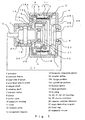
- Fig. 1 is a side sectional view of a reduction gears-integrated actuator, which shows a first embodiment of the invention
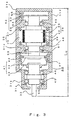
- Fig. 2 is a side sectional view of a reduction gears-integrated actuator, which shows a second embodiment of the invention
- Fig. 3 is a side sectional view showing a prior art reduction gears-integrated actuator.
- Fig. 1 is a side sectional view of a reduction gears-integrated actuator, which shows a first embodiment of the invention.
- 1 denotes an actuator
- 2 denotes an actuator frame
- 3 denotes a load-side bracket
- 4 denotes an anti-load side bracket
- 5 denotes an output shaft
- 6 denotes an rotation shaft
- 7 denotes an electric motor
- 8 denotes a stator
- 9 denotes a stator core
- 10 denotes an armature winding
- 11 denotes a rotor
- 12 denotes a rotation yoke
- 13 denotes a permanent magnet
- 14 denotes harmonic reduction gears
- 15 denotes a circular spline
- 16 denotes a flexible spline
- 17 denotes a wave generator
- 18 denotes a housing
- 19, 20, 21, 22 and 23 denote bearings
- 24 and 25 denote elastic members
- 26 denotes a rotation position detector
- 27 denotes an angle detecting magnet
- 28 denotes a fixed ring
- 29 denotes a magnetic sensor
- an actuator according to the invention that is, a construction employing harmonic reduction gears 14, electric motor 7 and rotation position detector 26, and a construction in which the output shaft 5 disposed at the load side is supported by the bearings 19 and 20 and a preload is applied by the elastic member 24 are the same as those of prior arts.
- the present invention differs from the prior arts in the following four points. That is,
- the magnetic sensor 29 of the rotation position detector 26 employs a hole effect element.
- Fig. 2 is a side sectional view of a reduction gears-integrated actuator, which shows the second embodiment of the invention.
- the second embodiment includes components which are similar to those of the first embodiment, and parts which are identical to those in the first embodiment are given the same reference numbers. Also, the housing portion provided between the output shaft of the actuator and the rotation shaft thereof, construction and effects of the rotation position detector are the same as those of the first embodiment, and overlapping description thereof is omitted.
- the second embodiment differs from the first embodiment in view of the following two points. That is,
- the electric motor 7 and harmonic reduction gears 14 are provided on the inner circumference of the same actuator frame 1, it is possible to shorten the length of the entire actuator in its axial direction, whereby if the length L 2 of the actuator in the axial direction in Fig. 2 is compared with the length L 0 of the prior art actuator shown in Fig. 3 in the axial direction, the length L 2 can be shortened by approx. 40%, and this greatly contributes to the downsizing thereof. Also, since actions of the second embodiment are similar to those of the first embodiment, description thereof is omitted.
- the rotation yoke that constitutes the rotor is formed to be cup-shaped, and the harmonic reduction gears are disposed by utilizing a space formed between the inner circumferential side of the cup-shaped rotation yoke and the rotation shaft, and at the same time an electric motor composed of a stator and a rotor is installed on the outer circumferential side of the harmonic reduction gears, the harmonic reduction gears and the electric motor are disposed so that the lengths thereof in the axial direction almost concentrically overlap with respect to the diametrical direction.
- the actuator according to the invention is compared with the prior art actuator in which the actuator frame is composed of three components, the number of components can be decreased by one, and this contributes to a decrease in the number of assembling steps, wherein an inexpensive actuator can be proposed.
- the rotation yoke of the rotor is cup-shaped, the outer diametrical portion of which has a large hollow portion, the weight of the rotor can be decreased to lighten the weight. Therefore, the actuator can be downsized in the axial direction, and even where a high torque is requested, it is possible to increase the drive force without running counter to the downsizing and lightening of the weight.
- a plate spring, a coil spring, etc. may be used as the elastic member for applying a preload between the bearings.
- the elastic member is not limited, wherein any means which can substitute the same may be used.
- an amorphous wire in which a magnetic resistance element or a magnetic impedance effect is utilized may be used as the magnetic sensor of the rotation position detector, instead of the hole-effect element.
- a reduction gears-integrated actuator according to the invention in which an electric motor and harmonic reduction gears are integrated can be usefully used in, for example, robots, machine tools, etc.
Landscapes
- Engineering & Computer Science (AREA)
- General Engineering & Computer Science (AREA)
- Power Engineering (AREA)
- Mechanical Engineering (AREA)
- Connection Of Motors, Electrical Generators, Mechanical Devices, And The Like (AREA)
- Retarders (AREA)
Abstract
In a reduction gears-integrated actuator that is provided
with harmonic reduction gears 14, an electric motor 7 and a
rotation position detector 26, the rotor 11 is composed of a
cup-shaped rotation yoke 12, a permanent magnet 13 is fixed
on the outer circumference of the rotation yoke 12, a circular
spline 15 is formed to be like a silk hat, the flange portion
15a is fixed at one end portion of the actuator frame 2, and
the cylindrical portion 15b is disposed opposite to the inner
circumference of the rotation yoke 12 via a gap. A cup-shaped
housing 18 that is coupled to the output shaft 5 is provided
on the inner circumferential side of the flexible spline 16
between the output shaft 5 and the rotation shaft 6, and an
elastic member 25 that gives a preload is provided between the
housing 18 and the bearing 21 for supporting the rotation shaft
6, whereby it is possible to shorten the length of the actuator
in its axial direction, and a drive torque can be increased
without running counter to downsizing and lightening of the
weight thereof. That is, it is possible to provide an inexpensive
reduction gears-integrated actuator.
Description
The present invention relates to an inexpensive reduction
gears-integrated actuator that is capable of shortening the
length of the entire actuator in its axial direction and
increasing a drive torque without running counter to downsizing
and lightening of its weight.
Conventionally, an actuator used for a robot, a machine
tool, etc., in which harmonic reduction gears and an electric
motor are integrated together is constructed as shown in Fig.
3.
Fig. 3 is a side sectional view of a prior art reduction
gears-integrated actuator.
In the drawing, 30 denotes an actuator, 31a denotes a load
side bracket, 31b, 31c and 31d denote actuator frames, 31e
denotes an anti-load side bracket, 32 denotes an output shaft,
33 denotes a rotation shaft, 34 denotes an electric motor, 35
denotes a stator, 36 denotes a stator core, 37 denotes an armature
winding, 38 denotes a rotor, 39 denotes a yoke, 40 denotes a
permanent magnet, 41 denotes harmonic reduction gears, 42
denotes a circular spline, 43 denotes a flexible spline, 44
denotes a wave generator, 45, 46, 47 48, and 49 denote bearings,
50 and 51 denote elastic members, 52 denotes a rotation position
detector, 53 denotes a rotation disk, 54 denotes a fixed slit,
55 denotes a light emitting element, 56 denotes a light receiving
element, and L0 indicates a length of the actuator 30 in its
axial direction.
Such a reduction gears-integrated actuator 30 has a
structure in which the harmonic reduction gears 41, electric
motor 34, and rotation position detector 52 are coupled to each
other in a series in the axial direction in order from the load
side to the anti-load side. Also, these devices are fixed inside
hollow cylindrical actuator frames 31b, 31c and 31d, and both
end portions are covered by the load side bracket 31a and the
anti-load side bracket 31e.
Of these, the harmonic reduction gears 41 are composed of
a circular spline 42 which is fixed on the inner circumference
of the actuator frame 31b, and at the same time is annular and
has inner teeth, the flexible spline 43 which is attached to
the inside of the circular spline 42, coupled to an output shaft
32, is cup-shaped and has outer teeth, and an elliptically shaped
wave generator 44 which is attached to the inside of the flexible
spline 43 via a bearing 47 and coupled to a rotation shaft 33.
Also, the bearings 45 and 46 support the output shaft 32 and
are given a preload by an elastic member 50. And, the bearings
48 and 49 support the rotation shaft 33 and are given a preload
by an elastic member 51.
Further, the electric motor 34 is provided with a rotor
38 composed of a yoke 39 fitted to the rotation shaft 33 and
a permanent magnet 40 that becomes a magnetic pole, and at the
same time a stator 35 composed of a stator core 36 secured opposite
to the outer circumferential side of the rotator 38 via a gap
and an armature winding 37 that generates a rotation magnetic
field at the stator core 36.
Further, the rotation position detector 52 is composed of
an optical type encoder including a rotation disk 53 that becomes
a rotation portion fixed at the rotation shaft 33, a fixed slit
54 that becomes a fixing portion of the rotation position
detector, which is opposed to the rotation portion, a light
emitting element 55, and a light receiving element 56. When
light from the light emitting element 55 is projected onto the
rotation disk 53, the light receiving element 56 repeats
receiving and non-receiving of light via the fixed slit and
detects the receiving and non-receiving of light as ON and OFF
electric signals. After that, an angle of the rotor is calculated
by a calculation circuit (not illustrated).
Next, a description is given of the actions thereof.
When a current flows from a drive circuit (not illustrated)
into the armature winding 37 of the stator 35, a drive torque
is generated in the permanent magnet 40 of the rotor 38, and
the rotor 38 rotates at a high speed by the drive torque. Next,
since the wave generator 44 coupled to the rotation shaft 33
of the rotor rotates, the flexible spline 43 is elliptically
flexed via the bearing 47 and is engaged with the circular spline
42 at both end positions in the long axis direction of an ellipse
in the wave generator 44. At this time, relative rotation is
generated between the flexible spline 43 and the circular spline
42, wherein a remarkably reduced rotation force is transmitted
from the flexible spline 43 to the output shaft 32 and is outputted
therefrom.
However, in the prior art, since the harmonic reduction
gears, electric motor and rotation position detector are coupled
to each other in a line in a series, the length in the axial
direction is made longer especially between the harmonic
reduction gears and the electric motor, and between the electric
motor and the rotation position detector. Further, the space
of the rotation position detector disposed in the axial direction
is increased, and this becomes a problem in view of downsizing
and lightening of the weight thereof.
Also, since the harmonic reduction gears, electric motor
and rotation position detector are, respectively, fixed at three
actuator frames, the number of components is increased,
resulting in an increase in the number of assembling steps,
wherein another problem occurs, resulting in an increase in
production costs thereof.
Further, there is a request for improving a torque capacity
of an actuator in addition to a request of attempting downsizing
and lightening of weight of the actuator. For this reason, it
is necessary to make large the outer diameter of the rotor at
a position where the permanent magnet thereof is installed,
and to increase a drive torque of the rotor. However, in a
structure in any of the prior arts, the outer diameter of the
stator and actuator frame is increased if the outer diameter
of the rotor is increased. Therefore, the cubic volume and weight
of the entire electric motor are incidentally increased, and
there is a problem which runs counter to the downsizing,
lightening of weight and increasing of the torque in an actuator.
The present invention was developed to solve these and other
problems, and it is therefore an object of the invention to
provide an inexpensive reduction gears-integrated actuator
that is capable of shortening the length of the entire actuator
in its axial direction and increasing a drive torque without
running counter to downsizing and lightening of its weight.
In order to solve the above-described problems, the
invention is constructed as described below.
A reduction gears-integrated actuator according to the
first aspect of the invention comprises a hollow cylindrical
actuator frame; a circular spline that is fixed on the
above-described actuator frame and has inner teeth on the inner
circumference thereof; a cylindrical flexible spline that has
outer teeth engageable with the inner teeth of the
above-described circular spline, and has an output shaft of
the actuator coupled to the end face thereof; a elliptical wave
generator attached on the inner circumference of the
above-described flexible spline; a rotation shaft for driving
to rotate the above-described wave generator; an electric motor
including a rotor provided with a magnetic pole consisting of
a permanent magnet and stator provided with an armature winding
for generating a rotation magnetic field at a stator core opposed
to the outer circumferential side of the above-described rotor
via a gap; a rotation portion of a rotation position detector
fixed on the above-described rotation shaft; and a fixing portion
of the rotation position detector, which is opposed to the
rotation portion of the above-described rotation position
detector; wherein the above-described rotor constitutes a
cup-shaped rotation yoke integrally mounted at the center
thereof so as to pass through the above-described rotation shaft,
and at the same time fixes the above-described permanent magnet
on the outer circumference of the above-described rotation yoke;
the above-described circular spline is formed to be like a silk
hat and at the same time, the cylindrical portion thereof is
disposed so as to oppose the inner circumference of the
above-described rotation yoke via a gap while the flange portion
is fixed at one end portion of the above-described actuator
frame; and the above-described circular spline is further
provided, between the above-described output shaft and the
above-described rotation shaft, with a cup-shaped housing
coupled to the above-described output shaft on the inner
circumferential side of the above-described flexible spline,
a bearing that is fitted to the inside of the above-described
housing and supports the above-described rotation shaft, and
an elastic member that is provided in a gap in the axial direction
between the above-described housing and the above-described
bearing, and gives a preload to the above-described bearing.
Also, the reduction gears-integrated actuator according
to the second aspect of the invention is constructed, in addition
to the reduction gears-integrated actuator as set forth in the
first aspect, so that the rotation portion of the above-described
rotation position detector is composed of a disk-shaped magnet
for detecting an angle, which is magnetized in a direction
perpendicular to the above-described rotation shaft, and the
fixing portion of the above-described rotation position
detector is composed of a fixed ring provided on the outer
circumferential side of the rotation portion of the
above-described rotation position detector, and at least two
magnetic sensors attached in the circumferential direction of
the fixed ring.
Further, the reduction gears-integrated actuator according
to the third aspect of the invention comprises a hollow
cylindrical actuator frame; a circular spline that is fixed
on the above-described actuator frame and has inner teeth on
the inner circumference thereof; a cylindrical flexible spline
that has outer teeth engageable with the inner teeth of the
above-described circular spline, and has an output shaft of
the actuator coupled to the end face thereof; a elliptical wave
generator attached on the inner circumference of the
above-described flexible spline; a rotation shaft for driving
to rotate the above-described wave generator; an electric motor
including a rotor provided with a magnetic pole consisting of
a permanent magnet and stator provided with an armature winding
for generating a rotation magnetic field at a stator core opposed
to the inner circumferential side of the above-described rotor
via a gap; a rotation portion of a rotation position detector
fixed on the above-described rotation shaft; and a fixing portion
of the rotation position detector, which is opposed to the
rotation portion of the above-described rotation position
detector; wherein the above-described rotor constitutes a
cup-shaped rotation yoke integrally mounted at the center
thereof so as to pass through the above-described rotation shaft,
and at the same time fixes the above-described permanent magnet
on the inner circumference of the above-described rotation yoke;
the above-described circular spline is formed to be like a silk
hat, and at the same time, the cylindrical portion thereof is
disposed so as to be fixed at the inner circumference side of
the above-described stator while the flange portion is fixed
at one end portion of the above-described actuator frame; and
the above-described circular spline is further provided,
between the above-described output shaft and the
above-described rotation shaft, with a cup-shaped housing
coupled to the above-described output shaft on the inner
circumferential side of the above-described flexible spline,
a bearing that is fitted to the inside of the above-described
housing and supports the above-described rotation shaft, and
an elastic member that is provided in a gap in the axial direction
between the above-described housing and the above-described
bearing, and gives a preload to the above-described bearing.
Also, the reduction gears-integrated actuator according
to the fourth aspect of the invention is constructed, in addition
to the reduction gears-integrated actuator as set forth in the
third aspect, so that the rotation portion of the above-described
rotation position detector is composed of a disk-shaped magnet
for detecting an angle, which is magnetized in a direction
perpendicular to the above-described rotation shaft, and the
fixing portion of the above-described rotation position
detector is composed of a fixed ring provided on the outer
circumferential side of the rotation portion of the
above-described rotation position detector, and at least two
magnetic sensors attached in the circumferential direction of
the fixed ring.
Fig. 1 is a side sectional view of a reduction
gears-integrated actuator, which shows a first embodiment of
the invention; Fig. 2 is a side sectional view of a reduction
gears-integrated actuator, which shows a second embodiment of
the invention; and Fig. 3 is a side sectional view showing a
prior art reduction gears-integrated actuator.
Hereinafter, a description is given of embodiments of the
invention on the basis of the accompanying drawings.
Fig. 1 is a side sectional view of a reduction
gears-integrated actuator, which shows a first embodiment of
the invention.
In the drawing, 1 denotes an actuator, 2 denotes an actuator
frame, 3 denotes a load-side bracket, 4 denotes an anti-load
side bracket, 5 denotes an output shaft, 6 denotes an rotation
shaft, 7 denotes an electric motor, 8 denotes a stator, 9 denotes
a stator core, 10 denotes an armature winding, 11 denotes a
rotor, 12 denotes a rotation yoke, 13 denotes a permanent magnet,
14 denotes harmonic reduction gears, 15 denotes a circular spline,
16 denotes a flexible spline, 17 denotes a wave generator, 18
denotes a housing, 19, 20, 21, 22 and 23 denote bearings, 24
and 25 denote elastic members, 26 denotes a rotation position
detector, 27 denotes an angle detecting magnet, 28 denotes a
fixed ring, 29 denotes a magnetic sensor, and L1 indicates a
length of the actuator 1 in its axial direction.
The basic constructions of an actuator according to the
invention, that is, a construction employing harmonic reduction
gears 14, electric motor 7 and rotation position detector 26,
and a construction in which the output shaft 5 disposed at the
load side is supported by the bearings 19 and 20 and a preload
is applied by the elastic member 24 are the same as those of
prior arts. However, the present invention differs from the
prior arts in the following four points. That is,
Herein, the magnetic sensor 29 of the rotation position
detector 26 employs a hole effect element.
In such a construction, since the electric motor 7 and
harmonic reduction gears 14 are provided on the inner
circumference of the same actuator frame 1, respective spaces
conventionally required for the harmonic reduction gears and
electric motor to be arranged in series in a line in the axial
direction are not required any longer, wherein only a single
space is sufficient. Also, since the rotation position detector
is disposed in the diametrical direction instead of a
conventional one in which the rotation portion and fixing portion
are disposed in the axial direction, the space for accommodating
the same can be made small, and it is possible to shorten the
length of the entire actuator in the axial direction. Therefore,
if the length L1 of the actuator in its axial direction in Fig.
1 is compared with the length L0 of the prior art actuator in
its axial direction shown in Fig. 3, the length L1 can be shortened
by approx. 40%, and this greatly contributes to the downsizing
thereof.
Next, a description is given of the actions.
When an electric current flows from a drive circuit (not
illustrated) into the armature winding 10 of the stator 8, a
drive torque is generated at the permanent magnet 13 of the
rotor 11, and the rotor 11 rotates at high speed by the drive
torque. Next, since the wave generator 17 which is coupled to
the rotation shaft 6 of the rotor is rotated, the flexible spline
16 is flexed to be elliptical via the bearing 22, and is engaged
with the circular spline 15 at both end positions in the longer
axial direction of an ellipse in the wave generator 17. At this
time, relative rotation is generated between the flexible spline
16 and the circular spline 15, wherein a remarkably reduced
rotation force is transmitted from the flexible spline 16 to
the output shaft 5, and is outputted therefrom. At this time,
the magnetic sensor 29 opposed to the magnet 27 for detecting
an angle, which is attached to the rotation shaft 6, detects
magnetic field positions of the rotating magnet 27 for detecting
an angle as electric signals, and the angular position of
rotation of the rotation shaft is calculated by a calculation
circuit (not illustrated) on the basis of the electric signals.
Next, a description is given of the second embodiment of
the invention.
Fig. 2 is a side sectional view of a reduction
gears-integrated actuator, which shows the second embodiment
of the invention. The second embodiment includes components
which are similar to those of the first embodiment, and parts
which are identical to those in the first embodiment are given
the same reference numbers. Also, the housing portion provided
between the output shaft of the actuator and the rotation shaft
thereof, construction and effects of the rotation position
detector are the same as those of the first embodiment, and
overlapping description thereof is omitted.
The second embodiment differs from the first embodiment
in view of the following two points. That is,
In such a construction, as in the first embodiment, since
the electric motor 7 and harmonic reduction gears 14 are provided
on the inner circumference of the same actuator frame 1, it
is possible to shorten the length of the entire actuator in
its axial direction, whereby if the length L2 of the actuator
in the axial direction in Fig. 2 is compared with the length
L0 of the prior art actuator shown in Fig. 3 in the axial direction,
the length L2 can be shortened by approx. 40%, and this greatly
contributes to the downsizing thereof. Also, since actions of
the second embodiment are similar to those of the first
embodiment, description thereof is omitted.
Therefore, since, in the first embodiment and the second
embodiment, the rotation yoke that constitutes the rotor is
formed to be cup-shaped, and the harmonic reduction gears are
disposed by utilizing a space formed between the inner
circumferential side of the cup-shaped rotation yoke and the
rotation shaft, and at the same time an electric motor composed
of a stator and a rotor is installed on the outer circumferential
side of the harmonic reduction gears, the harmonic reduction
gears and the electric motor are disposed so that the lengths
thereof in the axial direction almost concentrically overlap
with respect to the diametrical direction. And, respective
spaces conventionally required for connecting the harmonic
reduction gears and electric motor in series in the axial
direction are not required any longer, wherein only a single
space for accommodating these two devices is sufficient, and
the electric motor and harmonic reduction gears can be
accommodated on the inner circumference of the same actuator
frame. Further, since the rotation position detector is disposed
in the diametrical direction, it is possible to shorten the
length of the entire actuator in its axial direction. Therefore,
it is possible to provide a small-sized actuator which is light
in weight.
Also, as a result, where the actuator according to the
invention is compared with the prior art actuator in which the
actuator frame is composed of three components, the number of
components can be decreased by one, and this contributes to
a decrease in the number of assembling steps, wherein an
inexpensive actuator can be proposed.
In addition, since the rotation yoke of the rotor is
cup-shaped, the outer diametrical portion of which has a large
hollow portion, the weight of the rotor can be decreased to
lighten the weight. Therefore, the actuator can be downsized
in the axial direction, and even where a high torque is requested,
it is possible to increase the drive force without running
counter to the downsizing and lightening of the weight.
Also, in the respective embodiments, a description was given
of the example of an electric motor, in which an armature winding
is provided at the stator side and a magnetic circuit including
a permanent magnet is provided at the rotor side. However, the
embodiments are not limited to the above-described example,
and at least any one of the stator side and the rotor side may
be constructed of another magnetic circuit.
In addition, for example, a plate spring, a coil spring,
etc., may be used as the elastic member for applying a preload
between the bearings. The elastic member is not limited, wherein
any means which can substitute the same may be used.
Further, an amorphous wire in which a magnetic resistance
element or a magnetic impedance effect is utilized may be used
as the magnetic sensor of the rotation position detector, instead
of the hole-effect element.
As described above, a reduction gears-integrated actuator
according to the invention, in which an electric motor and
harmonic reduction gears are integrated can be usefully used
in, for example, robots, machine tools, etc.
Claims (4)
- A reduction gears-integrated actuator comprising: a hollow cylindrical actuator frame; a circular spline that is fixed on said actuator frame and has inner teeth on the inner circumference thereof; a cylindrical flexible spline that has outer teeth engageable with the inner teeth of said circular spline, and has an output shaft of the actuator coupled to the end face thereof; an elliptical wave generator attached on the inner circumference of said flexible spline; a rotation shaft for driving to rotate said wave generator; an electric motor including a rotor provided with a magnetic pole consisting of a permanent magnet and stator provided with an armature winding for generating a rotation magnetic field at a stator core opposed to the outer circumferential side of said rotor via a gap; a rotation portion of a rotation position detector fixed on said rotation shaft; and a fixing portion of the rotation position detector, which is opposed to the rotation portion of said rotation position detector;
wherein said rotor constitutes a cup-shaped rotation yoke integrally mounted at the center thereof so as to pass through said rotation shaft, and at the same time fixes said permanent magnet on the outer circumference of said rotation yoke;
said circular spline is formed to be like a silk hat, and at the same time, the cylindrical portion thereof is disposed so as to oppose the inner circumference of said rotation yoke via a gap while the flange portion is fixed at one end portion of said actuator frame; and
said circular spline is further provided, between said output shaft and said rotation shaft, with a cup-shaped housing coupled to said output shaft on the inner circumferential side of said flexible spline, a bearing that is fitted to the inside of said housing and supports said rotation shaft, and an elastic member that is provided in a gap in the axial direction between said housing and said bearing, and gives a preload to said bearing. - The reduction gears-integrated actuator as set forth in Claim 1, wherein the rotation portion of said rotation position detector is composed of a disk-shaped magnet for detecting an angle, which is magnetized in a direction perpendicular to said rotation shaft, and the fixing portion of said rotation position detector is composed of a fixed ring provided on the outer circumferential side of the rotation portion of said rotation position detector, and at least two magnetic sensors attached in the circumferential direction of the fixed ring.
- A reduction gears-integrated actuator comprising: a hollow cylindrical actuator frame; a circular spline that is fixed on said actuator frame and has inner teeth on the inner circumference thereof; a cylindrical flexible spline that has outer teeth engageable with the inner teeth of said circular spline, and has an output shaft of the actuator coupled to the end face thereof; an elliptical wave generator attached on the inner circumference of said flexible spline; a rotation shaft for driving to rotate said wave generator; an electric motor including a rotor provided with a magnetic pole consisting of a permanent magnet and stator provided with an armature winding for generating a rotation magnetic field at a stator core opposed to the inner circumferential side of said rotor via a gap; a rotation portion of a rotation position detector fixed on said rotation shaft; and a fixing portion of the rotation position detector, which is opposed to the rotation portion of said rotation position detector;
wherein said rotor constitutes a cup-shaped rotation yoke integrally mounted at the center thereof so as to pass through said rotation shaft, and at the same time fixes said permanent magnet on the inner circumference of said rotation yoke;
said circular spline is formed to be like a silk hat, and at the same time, the cylindrical portion thereof is disposed so as to be fixed at the inner circumference side of said stator while the flange portion is fixed at one end portion of said actuator frame; and
said circular spline is further provided, between said output shaft and said rotation shaft, with a cup-shaped housing coupled to said output shaft on the inner circumferential side of said flexible spline, a bearing that is fitted to the inside of said housing and supports said rotation shaft, and an elastic member that is provided in a gap in the axial direction between said housing and said bearing, and gives a preload to said bearing. - The reduction gears-integrated actuator as set forth in Claim 3, wherein the rotation portion of said rotation position detector is composed of a disk-shaped magnet for detecting an angle, which is magnetized in a direction perpendicular to said rotation shaft, and the fixing portion of said rotation position detector is composed of a fixed ring provided on the outer circumferential side of the rotation portion of said rotation position detector, and at least two magnetic sensors attached in the circumferential direction of the fixed ring.
Applications Claiming Priority (3)
| Application Number | Priority Date | Filing Date | Title |
|---|---|---|---|
| JP28440099A JP2001112215A (en) | 1999-10-05 | 1999-10-05 | Reducer integrated actuator |
| JP28440099 | 1999-10-05 | ||
| PCT/JP2000/006966 WO2001026203A1 (en) | 1999-10-05 | 2000-10-05 | Reduction gears-integrated actuator |
Publications (2)
| Publication Number | Publication Date |
|---|---|
| EP1221755A1 true EP1221755A1 (en) | 2002-07-10 |
| EP1221755A4 EP1221755A4 (en) | 2008-07-30 |
Family
ID=17678091
Family Applications (1)
| Application Number | Title | Priority Date | Filing Date |
|---|---|---|---|
| EP00964702A Withdrawn EP1221755A4 (en) | 1999-10-05 | 2000-10-05 | ACTUATOR INTEGRATED WITH REDUCING GEAR |
Country Status (7)
| Country | Link |
|---|---|
| US (1) | US6701803B1 (en) |
| EP (1) | EP1221755A4 (en) |
| JP (1) | JP2001112215A (en) |
| KR (1) | KR100680152B1 (en) |
| CN (1) | CN1182642C (en) |
| TW (1) | TW486850B (en) |
| WO (1) | WO2001026203A1 (en) |
Cited By (7)
| Publication number | Priority date | Publication date | Assignee | Title |
|---|---|---|---|---|
| EP1403155A3 (en) * | 2002-09-30 | 2005-04-20 | Robert Bosch Gmbh | Symmetric motor for wiper elements |
| DE10206748B4 (en) * | 2001-02-19 | 2010-07-08 | Harmonic Drive Systems Inc. | Actuator with a shaft gear reduction mechanism |
| WO2011029472A1 (en) * | 2009-09-09 | 2011-03-17 | Abb Research Ltd | Drive assembly, industrial robot, robot boom and robot joint |
| ITMI20111098A1 (en) * | 2011-06-17 | 2012-12-18 | Micromeccanica Di Prec E S R L | ELECTROMECHANICAL DEVICE FOR THE ADJUSTMENT OF GUIDES OF AIR CONVEYORS |
| EP2424081A4 (en) * | 2009-04-21 | 2013-11-13 | Toyota Motor Co Ltd | ENGINE WITH TRANSMISSION FUNCTION |
| DE102014220110A1 (en) * | 2014-10-02 | 2016-04-07 | Schunk Gmbh & Co. Kg Spann- Und Greiftechnik | Gripper or swivel unit |
| EP3439152A4 (en) * | 2016-03-30 | 2019-11-13 | Nidec Corporation | ROTARY ACTUATOR AND ROBOT |
Families Citing this family (41)
| Publication number | Priority date | Publication date | Assignee | Title |
|---|---|---|---|---|
| JP4401229B2 (en) * | 2004-04-23 | 2010-01-20 | 株式会社ハーモニック・ドライブ・システムズ | Actuator with wave gear reducer |
| JP4787753B2 (en) * | 2004-07-02 | 2011-10-05 | 本田技研工業株式会社 | Drive unit with reduction gear |
| KR100798087B1 (en) * | 2004-07-02 | 2008-01-28 | 혼다 기켄 고교 가부시키가이샤 | Drive unit with reducer |
| GB0618902D0 (en) * | 2006-09-25 | 2006-11-01 | Airbus Uk Ltd | Actuator |
| JP4833028B2 (en) * | 2006-11-01 | 2011-12-07 | 株式会社ハーモニック・ドライブ・システムズ | Actuator with wave gear reducer |
| JP4560743B2 (en) * | 2008-01-25 | 2010-10-13 | 株式会社デンソー | Rotary actuator |
| US20100180696A1 (en) * | 2009-01-16 | 2010-07-22 | Delphi Technologies Inc. | Systems involving compact torque sensing |
| JP5403366B2 (en) * | 2010-02-02 | 2014-01-29 | 株式会社安川電機 | Motor with reduction gear |
| JP5764929B2 (en) * | 2010-04-14 | 2015-08-19 | 株式会社安川電機 | Linear rotary actuator |
| JP4615621B1 (en) * | 2010-06-22 | 2011-01-19 | 株式会社ツバキエマソン | Hollow fixed shaft reducer |
| JP2012070558A (en) * | 2010-09-24 | 2012-04-05 | Seiko Epson Corp | Electromechanical device, and actuator and motor using the same |
| JP2012147541A (en) * | 2011-01-11 | 2012-08-02 | Seiko Epson Corp | Electromechanical device, and actuator, motor, robot, and robot hand using the same |
| JP5445546B2 (en) * | 2011-09-22 | 2014-03-19 | 株式会社安川電機 | Rotating electric machine |
| US9293962B2 (en) | 2012-03-30 | 2016-03-22 | Korea Institute Of Machinery & Materials | Hollow driving module |
| TWM441059U (en) * | 2012-06-13 | 2012-11-11 | Harmonic Innovation Technology Co Ltd | Flexspline mounting structure of harmonic drive reducer |
| CN103807295A (en) * | 2012-11-06 | 2014-05-21 | 优必胜(上海)精密轴承制造有限公司 | Flexible thin-walled ball bearing used for robot |
| US9325229B2 (en) * | 2013-03-15 | 2016-04-26 | Hamilton Sundstrand Corporation | Generator architecture with PMG exciter and main field rotating power converter |
| DE102014007956A1 (en) * | 2014-05-26 | 2015-11-26 | Audi Ag | rotary damper |
| US10581298B2 (en) * | 2015-08-07 | 2020-03-03 | Kabushiki Kaisha Yaskawa Denki | Robot arm apparatus and actuator |
| KR101755943B1 (en) * | 2015-12-15 | 2017-07-07 | 현대자동차주식회사 | Harmonic drive having improved back drivabilituy, driving module comprising the harmonic drive and method for controlling the driving module |
| CN106224488B (en) * | 2016-08-31 | 2018-08-28 | 四川福德机器人股份有限公司 | A kind of integrated harmonic speed reducer device of built-in motor |
| JP2018084268A (en) * | 2016-11-22 | 2018-05-31 | Ntn株式会社 | Electric actuator |
| JP2018126032A (en) | 2017-02-03 | 2018-08-09 | 日本電産トーソク株式会社 | Electric actuator |
| US11264865B2 (en) * | 2017-02-28 | 2022-03-01 | Sony Corporation | Actuator |
| JP6819411B2 (en) | 2017-03-30 | 2021-01-27 | 日本電産トーソク株式会社 | Electric actuator |
| JP2018179252A (en) * | 2017-04-20 | 2018-11-15 | 日本電産シンポ株式会社 | Wave gear reduction unit and power unit having the same |
| JP6939185B2 (en) | 2017-07-25 | 2021-09-22 | 日本電産トーソク株式会社 | Electric actuator |
| US10844944B2 (en) * | 2017-08-25 | 2020-11-24 | Hamilton Sunstrand Corporation | Inverted harmonic gear actuator |
| JP7069673B2 (en) | 2017-12-06 | 2022-05-18 | 日本電産トーソク株式会社 | Electric actuator |
| JP2019118195A (en) | 2017-12-27 | 2019-07-18 | 日本電産トーソク株式会社 | Electric actuator, and rotation control mechanism |
| CN110380555B (en) * | 2019-07-27 | 2020-11-17 | 朱幕松 | Harmonic speed-reducing coreless brushless permanent magnet motor |
| FR3109481B1 (en) * | 2020-04-15 | 2024-10-25 | Moving Magnet Tech | Compact gear motor |
| US11942855B2 (en) * | 2020-08-12 | 2024-03-26 | Joby Aero, Inc. | Compact offset outrunner harmonic drive rotary actuator and deployment system using same |
| WO2022092839A1 (en) * | 2020-10-28 | 2022-05-05 | 주식회사 아모텍 | Driving motor equipped with bldc motor, and actuator using same |
| KR102634286B1 (en) * | 2020-12-24 | 2024-02-06 | 주식회사 아모텍 | Driving Motor Having BLDC Motor and Swivel Actuator Using the Same |
| KR102654827B1 (en) * | 2021-03-26 | 2024-04-04 | 주식회사 아모텍 | Driving Motor Having BLDC Motor and Swivel Actuator Using the Same |
| JP2024148659A (en) * | 2023-04-06 | 2024-10-18 | 株式会社ミツバ | Motor device |
| US12215770B1 (en) | 2023-12-20 | 2025-02-04 | Hamilton Sundstrand Corporation | Strain wave gear differential with high gear reduction |
| KR102890457B1 (en) * | 2023-12-29 | 2025-11-27 | 주식회사 엔엠씨 | Axial flux motor including a reduction member disposed on a stator |
| KR102890460B1 (en) * | 2023-12-29 | 2025-11-27 | 주식회사 엔엠씨 | Motor including magnetic reduction member |
| KR102890449B1 (en) * | 2023-12-29 | 2025-11-27 | 주식회사 엔엠씨 | Motor including a modulator formed integrally with a stator |
Family Cites Families (14)
| Publication number | Priority date | Publication date | Assignee | Title |
|---|---|---|---|---|
| US3128641A (en) * | 1962-06-05 | 1964-04-14 | United Shoe Machinery Corp | Power transmission |
| JPS60132166A (en) | 1983-12-20 | 1985-07-15 | Kawasaki Heavy Ind Ltd | Planetary gear |
| JPS60132166U (en) * | 1984-02-15 | 1985-09-04 | 株式会社安川電機 | Outer rotor type motor with reducer |
| DE3522336A1 (en) * | 1985-06-22 | 1987-01-02 | Bosch Gmbh Robert | ROBOT JOINT WITH AN ELECTRIC DRIVE MOTOR |
| FR2614363B1 (en) * | 1987-04-22 | 1991-01-04 | Mitsubishi Electric Corp | ENGINE STARTER |
| JPH01127349A (en) | 1987-11-12 | 1989-05-19 | Mitsubishi Heavy Ind Ltd | Plate cylinder phase control method of printing machine |
| JPH01127349U (en) * | 1988-02-24 | 1989-08-31 | ||
| JP2931865B2 (en) * | 1989-10-16 | 1999-08-09 | 株式会社安川電機 | Actuator with built-in motor |
| JP2505621B2 (en) * | 1990-06-21 | 1996-06-12 | 三菱電機株式会社 | Period / voltage conversion circuit |
| US4951518A (en) * | 1990-08-28 | 1990-08-28 | Candy Mfg. Co., Inc. | Zero back lash phase adjusting mechanism |
| JPH0756601Y2 (en) * | 1990-09-12 | 1995-12-25 | 株式会社安川電機 | Servo actuator |
| JPH11147465A (en) * | 1997-11-17 | 1999-06-02 | Akebono Brake Ind Co Ltd | Hydraulic control unit and brake system using former |
| US6257186B1 (en) * | 1999-03-23 | 2001-07-10 | Tcg Unitech Aktiengesellschaft | Device for adjusting the phase angle of a camshaft of an internal combustion engine |
| US6258007B1 (en) * | 1999-05-27 | 2001-07-10 | Teijin Seiki Boston, Inc | Multi-sensor harmonic drive actuator arrangement assembly |
-
1999
- 1999-10-05 JP JP28440099A patent/JP2001112215A/en active Pending
-
2000
- 2000-10-04 TW TW089120684A patent/TW486850B/en active
- 2000-10-05 WO PCT/JP2000/006966 patent/WO2001026203A1/en not_active Ceased
- 2000-10-05 CN CNB008157782A patent/CN1182642C/en not_active Expired - Fee Related
- 2000-10-05 KR KR1020027004410A patent/KR100680152B1/en not_active Expired - Fee Related
- 2000-10-05 EP EP00964702A patent/EP1221755A4/en not_active Withdrawn
- 2000-10-05 US US10/089,062 patent/US6701803B1/en not_active Expired - Lifetime
Cited By (7)
| Publication number | Priority date | Publication date | Assignee | Title |
|---|---|---|---|---|
| DE10206748B4 (en) * | 2001-02-19 | 2010-07-08 | Harmonic Drive Systems Inc. | Actuator with a shaft gear reduction mechanism |
| EP1403155A3 (en) * | 2002-09-30 | 2005-04-20 | Robert Bosch Gmbh | Symmetric motor for wiper elements |
| EP2424081A4 (en) * | 2009-04-21 | 2013-11-13 | Toyota Motor Co Ltd | ENGINE WITH TRANSMISSION FUNCTION |
| WO2011029472A1 (en) * | 2009-09-09 | 2011-03-17 | Abb Research Ltd | Drive assembly, industrial robot, robot boom and robot joint |
| ITMI20111098A1 (en) * | 2011-06-17 | 2012-12-18 | Micromeccanica Di Prec E S R L | ELECTROMECHANICAL DEVICE FOR THE ADJUSTMENT OF GUIDES OF AIR CONVEYORS |
| DE102014220110A1 (en) * | 2014-10-02 | 2016-04-07 | Schunk Gmbh & Co. Kg Spann- Und Greiftechnik | Gripper or swivel unit |
| EP3439152A4 (en) * | 2016-03-30 | 2019-11-13 | Nidec Corporation | ROTARY ACTUATOR AND ROBOT |
Also Published As
| Publication number | Publication date |
|---|---|
| WO2001026203A1 (en) | 2001-04-12 |
| EP1221755A4 (en) | 2008-07-30 |
| KR100680152B1 (en) | 2007-02-07 |
| US6701803B1 (en) | 2004-03-09 |
| CN1390378A (en) | 2003-01-08 |
| TW486850B (en) | 2002-05-11 |
| KR20020038799A (en) | 2002-05-23 |
| JP2001112215A (en) | 2001-04-20 |
| CN1182642C (en) | 2004-12-29 |
Similar Documents
| Publication | Publication Date | Title |
|---|---|---|
| US6701803B1 (en) | Reduction gears-integrated actuator | |
| US8159096B2 (en) | Apparatus for detecting position of rotation of motor | |
| US11408485B2 (en) | Electric actuator | |
| JP2005261022A (en) | Axial gap rotating electric machine | |
| JP2009160721A (en) | Motorized rotary joint | |
| JP2019187167A (en) | Rotor, motor and brushless wiper motor | |
| KR100495352B1 (en) | Motor | |
| JP2019068517A (en) | Electric actuator | |
| JP7330010B2 (en) | Rotors, motors and brushless wiper motors | |
| US10418867B2 (en) | Switched reluctance motor | |
| JP4940022B2 (en) | motor | |
| US6969936B2 (en) | Rotational position detecting sensor-equipped motor and biaxial motor | |
| GB2574792A (en) | Rotationally balanced electric motor with air-core stator coils | |
| JP2004215397A (en) | Stepping motor | |
| US20250364867A1 (en) | Electric motor | |
| CN114039436B (en) | Rotor for rotating electrical machine | |
| JP2004048821A (en) | Brushless motor | |
| JP2543533Y2 (en) | Rotor origin return mechanism for electromagnetic finite rotary motor | |
| JP2022152336A (en) | motor | |
| CN114039436A (en) | Rotor for rotating electric machine | |
| JPH11178284A (en) | Rotation detector for motor | |
| CN119547313A (en) | Two-phase stepper motor | |
| CN120728940A (en) | A motor | |
| JP2015142439A (en) | Rare earth magnet motor | |
| JPH09163713A (en) | Stepping motor |
Legal Events
| Date | Code | Title | Description |
|---|---|---|---|
| PUAI | Public reference made under article 153(3) epc to a published international application that has entered the european phase |
Free format text: ORIGINAL CODE: 0009012 |
|
| 17P | Request for examination filed |
Effective date: 20020404 |
|
| AK | Designated contracting states |
Kind code of ref document: A1 Designated state(s): AT BE CH CY DE DK ES FI FR GB GR IE IT LI LU MC NL PT SE |
|
| RBV | Designated contracting states (corrected) |
Designated state(s): AT BE CH CY DE FR GB IT LI SE |
|
| A4 | Supplementary search report drawn up and despatched |
Effective date: 20080702 |
|
| 17Q | First examination report despatched |
Effective date: 20080912 |
|
| STAA | Information on the status of an ep patent application or granted ep patent |
Free format text: STATUS: THE APPLICATION IS DEEMED TO BE WITHDRAWN |
|
| 18D | Application deemed to be withdrawn |
Effective date: 20090123 |