EP1221639A2 - Programmierung von zyklischen Maschinen - Google Patents
Programmierung von zyklischen Maschinen Download PDFInfo
- Publication number
- EP1221639A2 EP1221639A2 EP01129877A EP01129877A EP1221639A2 EP 1221639 A2 EP1221639 A2 EP 1221639A2 EP 01129877 A EP01129877 A EP 01129877A EP 01129877 A EP01129877 A EP 01129877A EP 1221639 A2 EP1221639 A2 EP 1221639A2
- Authority
- EP
- European Patent Office
- Prior art keywords
- user
- level
- levels
- wait
- tasks
- Prior art date
- Legal status (The legal status is an assumption and is not a legal conclusion. Google has not performed a legal analysis and makes no representation as to the accuracy of the status listed.)
- Granted
Links
Images




Classifications
-
- G—PHYSICS
- G06—COMPUTING OR CALCULATING; COUNTING
- G06F—ELECTRIC DIGITAL DATA PROCESSING
- G06F9/00—Arrangements for program control, e.g. control units
- G06F9/06—Arrangements for program control, e.g. control units using stored programs, i.e. using an internal store of processing equipment to receive or retain programs
- G06F9/46—Multiprogramming arrangements
- G06F9/48—Program initiating; Program switching, e.g. by interrupt
- G06F9/4806—Task transfer initiation or dispatching
- G06F9/4843—Task transfer initiation or dispatching by program, e.g. task dispatcher, supervisor, operating system
- G06F9/4881—Scheduling strategies for dispatcher, e.g. round robin, multi-level priority queues
- G06F9/4887—Scheduling strategies for dispatcher, e.g. round robin, multi-level priority queues involving deadlines, e.g. rate based, periodic
-
- G—PHYSICS
- G05—CONTROLLING; REGULATING
- G05B—CONTROL OR REGULATING SYSTEMS IN GENERAL; FUNCTIONAL ELEMENTS OF SUCH SYSTEMS; MONITORING OR TESTING ARRANGEMENTS FOR SUCH SYSTEMS OR ELEMENTS
- G05B19/00—Program-control systems
- G05B19/02—Program-control systems electric
- G05B19/04—Program control other than numerical control, i.e. in sequence controllers or logic controllers
- G05B19/05—Programmable logic controllers, e.g. simulating logic interconnections of signals according to ladder diagrams or function charts
- G05B19/056—Programming the PLC
-
- G—PHYSICS
- G05—CONTROLLING; REGULATING
- G05B—CONTROL OR REGULATING SYSTEMS IN GENERAL; FUNCTIONAL ELEMENTS OF SUCH SYSTEMS; MONITORING OR TESTING ARRANGEMENTS FOR SUCH SYSTEMS OR ELEMENTS
- G05B2219/00—Program-control systems
- G05B2219/10—Plc systems
- G05B2219/15—Plc structure of the system
- G05B2219/15014—Configure priorities of different tasks
Definitions
- the invention relates to a method for programming of cyclic machines, in particular of production machines.
- This PLC / MC integration takes place in the form of interconnection of PLC and MC control modules. With one However, implementation of the integration will not be optimal and efficient Task structure for all control tasks reached. In addition, this type of integration mainly the classic MC functionalities as they are are particularly relevant for machine tools. Control requirements as they arise from operation of production machines are known by this type of interconnection of PLC and MC control modules not optimally supported.
- the invention is therefore based on the object for each different control tasks and different Boundary conditions or requirements of the underlying technical process in a simple way a configurable Execution level model for the control tasks of an industrial Create control for cyclic machines, the Programming the machine sequence in a sequential Program can be done.
- the tasks can be carried out Operation of the controller depending on its importance or requirements, that are placed on them (e.g. regarding the Response time behavior) at different priorities Expire come.
- Another advantage is that the Users in a sequential program with simple mechanisms complex synchronization conditions (e.g. waiting on the arrival of conditions) without that other mechanisms such as Event handlers required are.
- the user can run programs in the execution levels the functionality of the control very flexible to the underlying requirements of the technical process to adjust.
- a first embodiment of the present invention lies in that the execution levels consist of system levels and / or user levels to be created. This gives the user the opportunity very flexible a runtime system for an industrial Control to create that the respective requirements and boundary conditions of the technical process appropriate is.
- Another embodiment of the present invention lies in that the execution level model is clocked, the Basic clock from an internal timer or from an internal Clock of a communication medium or from an external device or of a size related to the technological process heard is derivable.
- This can be very flexible and very simply derived the basic clock for the execution level model become. Because the basic clock for the execution level model also of a size related to the technological process heard, derivable, can be done in a very simple way direct feedback from the technological process Control can be obtained.
- FIG. 1 shows the essential execution levels of a classic programmable logic controller (PLC), arranged according to their priority. The increase in priority is symbolized by an arrow.
- PLC programmable logic controller
- two different tasks namely a free cycle, ie "user level free cycle” and a background system level, ie "system level background” are carried out in the lowest priority level. Communication tasks are assigned to the background system level.
- user level time-controlled the call cycle of the tasks or programs at this level can be parameterized. Monitoring is carried out to determine whether the processing of a user program of this clocked level has been completed in good time before the start event occurs again.
- FIG. 2 shows the essential execution levels a motion control (MC).
- MC motion control
- a "system level background” and a “user level sequential” have one same priority, namely the lowest.
- This task-related Membership is as in FIG 1 by a dashed line Line symbolizes.
- the tasks of the "sequential user level” together with the tasks of the "system level background” processed in a round robin process.
- Typical tasks of "System level background” are e.g. those for communication tasks. They run in the "user level sequential" Program parts programmed by the user for the actual Control task.
- Tasks that relate to external tasks are housed here or internal events respond. Such events can for example alarms.
- a subsequent "user level synchronized clocked" synchronously clocked user tasks, eg controller functionalities, run. These tasks are synchronized with clocked system functions such as interpolators, position controllers or cyclical bus communication.
- FIG. 3 it is shown in the form of a structure picture that the control of a technical process P1 takes place via the runtime system RTS of an industrial control.
- the connection between the RTS runtime system of the controller and the technical process P1 is bidirectional via the inputs / outputs EA.
- the control system is programmed and the behavior of the RTS runtime system is defined in the ES engineering system.
- the engineering system ES contains tools for the configuration, project planning and programming for machines or for the control of technical processes.
- an engineering system ES usually consists of a computer system with a graphic screen (e.g. display), input aids (e.g. keyboard and mouse), processor, working and secondary memory, and a device for recording computer-readable media (e.g. floppy disks, CDs) as well as connection units for data exchange with other systems (e.g. further computer systems, controls for technical processes) or media (e.g. Internet).
- a controller usually consists of input and output units, as well as a processor and program memory. It is also conceivable that the control of a technical process P1 takes place via several runtime systems RTS from industrial controls.
- the representation according to FIG. 4 shows the execution level model of industrial control.
- the prioritization of levels will indicated by an arrow in the direction of the highest priority.
- the lowest priority levels are the "cyclical user level” and the “sequential user level”. These two levels run with the same priority. That is why they are Levels in the illustration of FIG 4 by a dashed line Line separated.
- the "cyclical user level” contains the “Background Task”, which is monitored for the cycle time.
- “Sequential "Motion tasks” are run through at the user level.
- “Motion tasks” are not monitored for cycle times and are mainly used to describe sequential processes.
- “Motion tasks” are processed quasi-parallel.
- all user levels contain one or more tasks.
- the tasks include the user programs.
- the tasks of "cyclical user level” and the “sequential user level” are processed in a common round robin cycle.
- the next level is the "time-controlled user level”.
- the tasks at this level are activated on a time-controlled basis.
- the timing is a granularity of milliseconds adjustable.
- This is followed by the "time-controlled user level” "event-driven user level”. Be at this level after detection of a user interrupt, so-called “user interrupt” Tasks "is activated.
- User interrupt events can be viewed as logical linking of process events and / or internal States can be formulated.
- the layer group "synchronously clocked layers" has the highest priority in the execution level model.
- the individual levels of this level group can have other priorities among themselves.
- the Layer group "synchronously clocked layers” consists of at least one system level and at least one user level.
- the system levels contain the system functions such as position controller or interpolator.
- In the user levels of this level group can be used by one user flexibly (AP1 - AP4; FIG 5) can be loaded.
- the Basic clock can e.g. from an internal timer (T1; FIG 10) come or from an internal clock (T3; FIG 10) of a communication medium (e.g. Profibus) or the clock can also derived from a process event of the technological process become.
- a process event can e.g. the Clock rate (TG; FIG 10) of an operation on a production machine or packaging machine.
- User levels of the level group "synchronously clocked levels” can be based be clocked on the basic clock, but they can also be synchronous to one of the system levels of the level group "synchronously clocked levels "run.
- the user tasks this one System level synchronous user level thus have a synchronous, i.e. deterministic relationship to one by the user system level that can be defined flexibly.
- This has the advantage that deterministic reactions to system tasks (system tasks are running in the system levels), which the user in his user tasks programmed in the user levels of the level group "synchronized clocked levels" run, guaranteed by the system become.
- time-controlled user level the "event-controlled User level”
- sequential user level the "event-controlled User level”
- cyclical User level the "user level for system exceptions " are optional.
- the task of the "cyclical user level” is cycle time monitoring.
- the "motion tasks”, however, are not monitored cycle time and are used mainly for description sequential processes. That is, the present process level model supports a user in both Programming of sequential processes as well Event programming. There can thus be synchronous events as well as asynchronous events recorded by programming become.
- the user levels are those created by the user User programs (AP1 - AP4; FIG 5) can be loaded.
- the User programs AP1 to AP4 are usually created using a programming environment of the engineering system (ES; FIG 3) created.
- FIG. 5 shows an exemplary embodiment for the loading of user programs into the user levels.
- FIG 5 shows an example of a version of user levels of the process level model. Through the three dots at the bottom of the The drawing shows that other user levels, but there can also be system levels.
- the Prioritization of levels is done as in the previous indicated an arrow in the direction of the highest priority.
- the assignment is represented by assignment arrows ZP1 to ZP4.
- In the user levels there are tasks that record the loaded user programs AP1 to AP4. This Tasks are then based on a certain strategy (e.g. sequentially) go through or processed. You can continue have the property that they monitor maturity are.
- the illustration according to FIG. 6 shows an exemplary embodiment for the use and mechanism of the Wait_for_Condition command, in the run-level model of the industrial invention Control.
- the Wait_for_Condition command (in FIG. 6 represented as wait_for_cond ()) in this representation used as an example in the "sequential user level”.
- the Wait_for_Condition command is created in the user "Motion Tasks" MT1 and MT2 used that component the "sequential user level”.
- the "Motion Tasks "MT1 and MT2 hang in a round robin cycle through the arrow from MT1 to MT2 and through the angled one Arrow from MT2 to MT1.
- the three dots inside This arrow indicates that further "motion tasks" in the Round robin cycle can hang.
- the "Motion Task” contains MT1 the Wait_for_Condition command “wait_for_cond (cond_1)", the “Motion Task” MT2 the Wait_for-Condition command "Wait_for_cond (cond_2)".
- Three points each within used by MT1 or MT2 indicate that in addition to the two Wait_for_Condition commands and the three positioning commands pos1 () to pos3 () other commands in the "Motion Tasks "can be included.
- condition cond_1 false, i.e. not fulfilled, is the "Motion Task" MT1 is interrupted immediately and in the round robin cycle MT2 is operated.
- the condition cond_1 is however in the "synchronously clocked system level 2" attached (indicated by the continuous angled arrow from wait_for_cond (cond_1) command to the "synchronously clocked system level 2 ") and in time with this system level to be fulfilled checked. If the condition cond_1 is fulfilled, the Round robin cycle displaces the current task, i.e. you will the time slice is removed and the motion task MT1 is activated immediately immediately after the wait_for_cond (cond_1) with the positioning command pos2 () continued. Through the dashed arrow the return from the "synchronously clocked system level 2 "for the positioning command pos2 (), i.e. for the" sequential user level " indicated.
- the conditions queried in a Wait_for_Condition command can be very flexible and elegant by the user be formulated. So the user can formulate this Conditions program variables from a user program use or internal sizes of control or he can too Reference process signals. These sizes can then logically arithmetically or with any functions can be linked to formulate a condition.
- the condition is fulfilled also associated program code, i.e. one behind Response that is user programmable is executed with high priority. And only after the execution this program code returns to the lower priority level he follows.
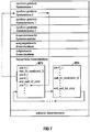
- the Wait_for_Condition command (also shown in FIG 7 as wait_for_cond ()) is exemplified in this representation in the "sequential User level "is used.
- the Wait_for_Condition command is used in the "Motion Tasks" MT3 and MT4 created by the user used, which is part of the "sequential user level” are.
- the "Motion Tasks" MT3 and MT4 hang in a round robin cycle, represented by the arrow from MT3 to MT4 and through the angled arrow from MT4 to MT3.
- the three Dots within this arrow indicate that there are more "Motion tasks" can hang in a round robin cycle.
- the "Motion Task "MT3 contains the Wait_for_Condition command “wait_for_cond (cond_3)", the “Motion Task” MT4 the Wait_for-Condition command "Wait_for_cond (cond_4)".
- Three points each, that are used within MT3 or MT4 assumes that in addition to the two Wait_for_Condition commands and the Position commands pos4 () to pos8 () still further commands in the "Motion Tasks" can be included.
- condition cond_3 false, ie not met, is the "Motion Task" MT3 is interrupted immediately and in the round robin cycle MT4 is operated.
- condition cond_3 is fulfilled, is with the priority of the "synchronously clocked system level 2 "the associated program sequence (here: the sequence of the commands pos5 () and pos6 () processed.
- the Dashed arrow indicates the return from the "synchronously timed System level 2 "for the positioning command pos7 (), i.e. indicated for "sequential user level”.
- a possible application is print mark synchronization. It's about a print mark on a material recognizable with high priority. When this print mark is recognized typically an actual value is recorded ("latching" e.g. of a location or encoder actual value). Based on this recorded actual value a correction value is calculated which is superimposed on the system Movement is imprinted. The process of actual value detection, Correction value calculation and implementation of the superimposed Movement must take place in a deterministic period of time respectively. That is why this process must take place with high priority.
- Another application is the "quick start of movement”. This is about, e.g. Edge change very quickly to recognize and immediately start a movement (e.g. positioning movement).
- the deterministic Detect an event and trigger follow-up actions is crucial for the productivity of a machine. at Production machines need such cyclical operations in one deterministic time, e.g. ⁇ 100 ms or ⁇ 50 ms. When processing the tasks on a normal background level this deterministic cannot be guaranteed.
- the mechanism described is particularly for use suitable for machines that have periodic machine cycles.
- the performance is further increased by the fact that when checking the conditions in the respective high-priority "synchronously clocked system levels "only pending conditions be attached and taken into account.
- the Wait_for_Condition command can be very flexible by the user and easy to use because it works as a normal programming language Construct is available.
- the wording too the conditions are flexible for a user and simple. So the user can formulate these conditions Use program variables from a user program or internal variables of the controller or it can also process signals reference. These quantities can then be logical, arithmetic or linked with any functions to formulate a condition.
- a user has the Possibility in normal user programs for motion sequences, a user program temporarily to a higher priority level to guarantee deterministic processes to be able to.
- the representation according to FIG. 8 shows the programming language construct the wait_for_condition mechanism as a syntax diagram.
- the terminal elements are with rounded corners shown: “WAITFORCONDITION”, “WITH”, “DO”, “END_WAITFORCONDITION” and “;”.
- the non-terminals are rectangles Elements shown: “Expression designation, "SWITCH” and “INSTRUCTION PART”.
- the elements "WITH” and “SWITCHES” are optional.
- FIG. 9 shows the use of the Wait_for_Condition construct in a program flow.
- the formulation of the condition "my expression” shown in the upper part of FIG. 9 is the formulation of the condition "my expression" shown, in the lower part is shown how uses this condition in a Wait_for_Condition construct becomes.
- 10 shows a schematic representation Possibilities like the basic clock for industrial control is won.
- 10 shows an example of a communication topology, in which the control S is integrated.
- the Control S is represented by a rectangle.
- the controller S is connected to the bus B1, on which the external device is connected via a connection cable A1 EG hangs.
- the technical process P2 is at the bottom Image edge represented by a rectangle.
- the controller S is connected to the bus B2, which in turn connects via the connection line A4 for the technical process P2.
- the generation for the basic cycle of the control S can be done different clock sources. So e.g. from an internal Clock source, represented by the internal timer T2 the control S or by an external clock source such as e.g. the timer T1, which belongs to the external device EG. As an external Clock source can also be the basic clock of a communication medium serve. If the bus B2 e.g. by an equidistant Profibus is realized, then the clock for the control can be obtained from the basic clock of this bus. This is shown in FIG. 10 in that the timer T3 is positioned directly on the connecting line A3, and this connection line A3 provides the connection to bus B2 ago. The controller is therefore connected to the bus as a slave and can be used directly use the bus clock.
- an internal Clock source represented by the internal timer T2 the control S or by an external clock source such as e.g. the timer T1 which belongs to the external device EG.
- an external Clock source can also be the basic clock of a communication medium serve.
- a TG clock in a technical process can e.g. the work cycle of a production machine or packaging machine his. 10 are shown in the illustration Bus connections are shown as communication media. But it can also be used as a communication medium Ring, star or other connection types can be selected, also wireless connections. From these connection systems the basic clock mentioned above can then be derived.
Landscapes
- Engineering & Computer Science (AREA)
- Physics & Mathematics (AREA)
- General Physics & Mathematics (AREA)
- Software Systems (AREA)
- Theoretical Computer Science (AREA)
- Automation & Control Theory (AREA)
- General Engineering & Computer Science (AREA)
- Programmable Controllers (AREA)
Abstract
Description
- FIG 1
- die wesentlichen Ablaufebenen einer klassischen speicherprogrammierbaren Steuerung,
- FIG 2
- die wesentlichen Ablaufebenen einer Bewegungssteuerung,
- FIG 3
- schematische Darstellung einer industriellen Steuerung,
- FIG 4
- das Ablaufebenenmodell der erfindungsgemäßen industriellen Steuerung,
- FIG 5
- ein Ausführungsbeispiel für das Zuladen von Anwenderprogrammen in die Anwenderebenen,
- FIG 6
- ein Ausführungsbeispiel für den Gebrauch und den Mechanismus des Wait_for_Condition-Befehls, im Ablaufebenenmodell der erfindungsgemäßen industriellen Steuerung,
- FIG 7
- ein weiteres Ausführungsbeispiel für den Gebrauch und den Mechanismus des Wait_for_Condition-Befehls, im Ablaufebenenmodell der erfindungsgemäßen industriellen Steuerung,
- FIG 8
- die syntaktische Beschreibung des Wait_for_Condition-Befehls in einem Syntaxdiagramm,
- FIG 9
- ein Beispiel für die Formulierung einer Expression in programmiersprachlicher Notation und
- FIG 10
- in einer Schemadarstellung Möglichkeiten, wie der Grundtakt für die industrielle Steuerung gewonnen wird.
Auf die "Anwenderebene zeitgesteuert" folgt eine "Anwenderebene Events". Die Reaktion auf externe oder interne Ereignisse (Events) erfolgt innerhalb der "Anwenderebene Events". Ein typisches Beispiel für ein solches Ereignis ist das Schalten eines binären bzw. digitalen Eingangs, wodurch typischerweise ein Ereignis ausgelöst wird. In einer "Systemebene hochprior" liegen die Aufgaben des Betriebssystems, welche die Arbeitsweise der programmierbaren Steuerung (SPS) sicherstellen.
In der Darstellung gemäß FIG 3 wird in Form eines Strukturbildes gezeigt, dass die Steuerung eines technischen Prozesses P1 über das Runtime-System RTS einer industriellen Steuerung erfolgt. Die Verbindung zwischen dem Runtime-System RTS der Steuerung und dem technischen Prozess P1 geschieht bidirektional über die Ein-/Ausgänge EA. Die Programmierung der Steuerung und damit das Festlegen des Verhaltens des Runtime-Systems RTS geschieht im Engineering-System ES. Das Engineering-System ES enthält Werkzeuge für die Konfigurierung, Projektierung und Programmierung für Maschinen bzw. für die Steuerung technischer Prozesse. Die im Engineering-System erstellten Programme werden über den Informationspfad I in das Runtime-System RTS der Steuerung übertragen. Bezüglich seiner Hardware-Ausstattung besteht ein Engineering-System ES üblicherweise aus einem Computersystem mit Graphikbildschirm (z.B. Display), Eingabehilfsmitteln (z.B. Tastatur und Maus), Prozessor, Arbeits- und Sekundärspeicher, einer Einrichtung für die Aufnahme computerlesbarer Medien (z.B. Disketten, CDs) sowie Anschlusseinheiten für einen Datenaustausch mit anderen Systemen (z.B. weiteren Computersystemen, Steuerungen für technische Prozesse) oder Medien (z.B. Internet). Eine Steuerung besteht üblicherweise aus Eingabe- und Ausgabeeinheiten, sowie aus Prozessor und Programmspeicher. Es ist auch vorstellbar, dass die Steuerung eines technischen Prozesses P1 über mehrere Runtime-Systeme RTS von industriellen Steuerungen erfolgt.
Claims (3)
- Verfahren zur Programmierung von zyklischen Maschinen, insbesondere von Produktionsmaschinen,
gekennzeichnet durch folgende aufeinander folgenden Schritte:wobei den Ablaufebenen System- und/oder Anwenderprogramme (AP1 - AP4) zugeordnet werden.d) Erstellen einer mit einem Runtime-System (RTS) ausgestatteten industriellen Steuerung (S) mit priorisierten Ablaufebenen und Tasks, wobei mindestens eine sequentielle Ablaufebene erstellt wird,e) Formulieren eines Maschinenablaufs in einem sequentiellen Programm undf) im sequentiellen Programm durch spezifische Mechanismen bereitstellen, dass1) das Warten auf das Erfülltsein von Bedingungen hochprior durchgeführt werden kann und2) dass nach Erfülltsein der Bedingung die nachfolgende Programmsequenz bis zu einem definierten anwenderprogrammierten Ende hochprior durchgeführt werden kann, - Verfahren zur Programmierung nach Anspruch 1,
dadurch gekennzeichnet, daß die Ablaufebenen aus Systemebenen und/oder Anwenderebenen erstellt werden. - Verfahren zur Programmierung nach Anspruch 1 oder 2,
dadurch gekennzeichnet, dass das Ablaufebenenmodell getaktet ist, wobei der Grundtakt aus einem internen Timer (T2) oder aus einem internen Takt (T3) eines Kommunikationsmediums (B1, B2) oder aus einem externen Gerät (EG) oder von einer Größe (TG), die zum technologischen Prozess (P1, P2) gehört ableitbar ist.
Applications Claiming Priority (2)
| Application Number | Priority Date | Filing Date | Title |
|---|---|---|---|
| DE10065417 | 2000-12-27 | ||
| DE10065417A DE10065417B4 (de) | 2000-12-27 | 2000-12-27 | Programmierung von zyklischen Maschinen |
Publications (3)
| Publication Number | Publication Date |
|---|---|
| EP1221639A2 true EP1221639A2 (de) | 2002-07-10 |
| EP1221639A3 EP1221639A3 (de) | 2006-08-09 |
| EP1221639B1 EP1221639B1 (de) | 2010-06-30 |
Family
ID=7669259
Family Applications (1)
| Application Number | Title | Priority Date | Filing Date |
|---|---|---|---|
| EP01129877A Expired - Lifetime EP1221639B1 (de) | 2000-12-27 | 2001-12-14 | Programmierung von zyklischen Maschinen |
Country Status (3)
| Country | Link |
|---|---|
| US (1) | US6978190B2 (de) |
| EP (1) | EP1221639B1 (de) |
| DE (2) | DE10065417B4 (de) |
Families Citing this family (6)
| Publication number | Priority date | Publication date | Assignee | Title |
|---|---|---|---|---|
| DE10023820B4 (de) * | 2000-05-15 | 2006-10-19 | Siemens Ag | Software-Schutzmechanismus |
| DE10216069A1 (de) * | 2002-04-11 | 2003-10-23 | Hauni Maschinenbau Ag | Verfahren und Vorrichtung zum Einwirken auf Artikel der tabakverarbeitenden Industrie |
| EP2477085B1 (de) * | 2011-01-13 | 2013-07-17 | Siemens Aktiengesellschaft | Verfahren und System zur Analyse eines zeitlichen Ablaufverhaltens eines Steuerungsprogramms einer Industriesteuerung |
| JP4877423B1 (ja) * | 2011-03-15 | 2012-02-15 | オムロン株式会社 | Plcのcpuユニット、plc用システムプログラムおよびplc用システムプログラムを格納した記録媒体 |
| DE102017005944B4 (de) * | 2017-06-23 | 2020-09-24 | Stefan Andreas Widmann | Vorrichtung und Verfahren zur gerätetechnischen Erkennung von Verletzungen von zyklischen Echtzeitbedingungen in Datenverarbeitungseinheiten und -systemen |
| JP7380390B2 (ja) * | 2020-03-31 | 2023-11-15 | オムロン株式会社 | 制御装置、プログラムおよび制御方法 |
Family Cites Families (16)
| Publication number | Priority date | Publication date | Assignee | Title |
|---|---|---|---|---|
| US5193189A (en) * | 1987-10-07 | 1993-03-09 | Allen-Bradley Company, Inc. | Programmable controller with multiple priority level task processing |
| US5012409A (en) * | 1988-03-10 | 1991-04-30 | Fletcher Mitchell S | Operating system for a multi-tasking operating environment |
| US5068778A (en) * | 1988-11-28 | 1991-11-26 | Reliance Electric Industrial Company | Industrial control system device |
| US5247675A (en) * | 1991-08-09 | 1993-09-21 | International Business Machines Corporation | Preemptive and non-preemptive scheduling and execution of program threads in a multitasking operating system |
| US5485620A (en) * | 1994-02-25 | 1996-01-16 | Automation System And Products, Inc. | Integrated control system for industrial automation applications |
| DE19500957A1 (de) * | 1994-07-19 | 1996-01-25 | Bosch Gmbh Robert | Verfahren zur Steuerung von technischen Vorgängen oder Prozessen |
| US5636124A (en) * | 1995-03-08 | 1997-06-03 | Allen-Bradley Company, Inc. | Multitasking industrial controller |
| ATE201777T1 (de) * | 1995-03-31 | 2001-06-15 | Siemens Ag | Verfahren zum betrieb einer werkzeugmaschine oder eines roboters |
| US5619409A (en) * | 1995-06-12 | 1997-04-08 | Allen-Bradley Company, Inc. | Program analysis circuitry for multi-tasking industrial controller |
| US5745386A (en) * | 1995-09-25 | 1998-04-28 | International Business Machines Corporation | Timing diagram method for inputting logic design parameters to build a testcase for the logic diagram |
| DE19625195A1 (de) * | 1996-06-24 | 1998-01-02 | Siemens Ag | Synchronisationsverfahren |
| DE29617837U1 (de) * | 1996-10-14 | 1997-11-13 | Siemens AG, 80333 München | Steuerung |
| US6093144A (en) | 1997-12-16 | 2000-07-25 | Symphonix Devices, Inc. | Implantable microphone having improved sensitivity and frequency response |
| US6430593B1 (en) * | 1998-03-10 | 2002-08-06 | Motorola Inc. | Method, device and article of manufacture for efficient task scheduling in a multi-tasking preemptive priority-based real-time operating system |
| US6360243B1 (en) * | 1998-03-10 | 2002-03-19 | Motorola, Inc. | Method, device and article of manufacture for implementing a real-time task scheduling accelerator |
| DE19915850C1 (de) * | 1999-04-08 | 2000-06-21 | Siemens Ag | Verfahren zum Abarbeiten mehrerer Befehlslisten in einer Datenverarbeitungsanlage |
-
2000
- 2000-12-27 DE DE10065417A patent/DE10065417B4/de not_active Expired - Fee Related
-
2001
- 2001-08-24 US US09/938,751 patent/US6978190B2/en not_active Expired - Fee Related
- 2001-12-14 DE DE50115537T patent/DE50115537D1/de not_active Expired - Lifetime
- 2001-12-14 EP EP01129877A patent/EP1221639B1/de not_active Expired - Lifetime
Also Published As
| Publication number | Publication date |
|---|---|
| US20020082721A1 (en) | 2002-06-27 |
| DE10065417A1 (de) | 2002-07-18 |
| DE10065417B4 (de) | 2011-07-21 |
| EP1221639A3 (de) | 2006-08-09 |
| US6978190B2 (en) | 2005-12-20 |
| DE50115537D1 (de) | 2010-08-12 |
| EP1221639B1 (de) | 2010-06-30 |
Similar Documents
| Publication | Publication Date | Title |
|---|---|---|
| EP1184758B1 (de) | Verfahren zum Debuggen von Programmen für industrielle Steuerungen, insbesondere Bewegungssteuerungen, im Kontext der Flow Chart Programmierung | |
| EP2422243B1 (de) | Sicherheitssteuerung zum steuern einer automatisierten anlage und verfahren zum erstellen eines anwenderprogramms für eine sicherheitssteuerung | |
| EP1248966B1 (de) | Universelle bewegungssteuerung | |
| EP2504738A1 (de) | Parallelisierte programmsteuerung | |
| EP3538960B1 (de) | Ablaufsteuerung von programmmodulen | |
| EP1221641B1 (de) | Industrielle Steuerung mit taktsynchronem Ablaufebenenmodell | |
| EP1238318B1 (de) | Automatisierungsgerät und aufdat-verfahren | |
| EP1220067B1 (de) | Integrationsverfahren für Automatisierungskomponenten | |
| EP2187281B1 (de) | Automatisierungsgerät und Verfahren zu dessen Betrieb | |
| DE10326542B4 (de) | Betriebsverfahren und Steuerungsprogramm für eine Zentraleinheit eines Automatisierungssystems sowie Zentraleinheit eines Automatisierungssystems und Automatisierungssystem selbst | |
| EP1220065B1 (de) | Verfahren zum Betrieb einer industriellen Steuerung mit Run-Time-System | |
| EP1221639B1 (de) | Programmierung von zyklischen Maschinen | |
| EP1067448B1 (de) | PC-System für Echtzeit- und Nicht-Echtzeitprogramme | |
| DE10038441B4 (de) | "Flow Chart Programmierung für industrielle Steuerungen, insbesondere Bewegungssteuerungen" | |
| EP0584512B1 (de) | Verfahren zum zeitlichen Überwachen einer Programmabarbeitung | |
| DE10055168A1 (de) | Industrielle Steuerung auf der Basis verteilbarer Technologischer Objekte | |
| DE10038439B4 (de) | Vorrichtung, zumindest umfassend ein Computersystem und eine industrielle Steuerung, für das Debuggen von Programmen für industrielle Steuerungen | |
| DE10114871A1 (de) | Verfahren zum Betrieb einer industriellen Steuerung | |
| EP1195667B1 (de) | Universelle Bewegungssteuerung | |
| EP1459182B1 (de) | Fehlertolerantes automatisierungssystem bzw. verfahren zur fehlerbehandlung bei einem echtzeit-automatisierungssystem | |
| EP1248967B1 (de) | Universelle bewegungssteuerung | |
| DE102016121542A1 (de) | Ablaufsteuerung von Programmmodulen | |
| EP4685586A1 (de) | Verfahren und taktverwaltung zur synchronisierten ausführung einer mehrzahl von echtzeitanwendungen | |
| DE19956271A1 (de) | Automatisierungsgerät und Aufdat-Verfahren | |
| DE10038440A1 (de) | Flow Chart Programmierung für industrielle Steuerungen, insbesondere Bewegungssteuerungen |
Legal Events
| Date | Code | Title | Description |
|---|---|---|---|
| PUAI | Public reference made under article 153(3) epc to a published international application that has entered the european phase |
Free format text: ORIGINAL CODE: 0009012 |
|
| AK | Designated contracting states |
Kind code of ref document: A2 Designated state(s): AT BE CH CY DE DK ES FI FR GB GR IE IT LI LU MC NL PT SE TR |
|
| AX | Request for extension of the european patent |
Free format text: AL;LT;LV;MK;RO;SI |
|
| PUAL | Search report despatched |
Free format text: ORIGINAL CODE: 0009013 |
|
| AK | Designated contracting states |
Kind code of ref document: A3 Designated state(s): AT BE CH CY DE DK ES FI FR GB GR IE IT LI LU MC NL PT SE TR |
|
| AX | Request for extension of the european patent |
Extension state: AL LT LV MK RO SI |
|
| 17P | Request for examination filed |
Effective date: 20060905 |
|
| 17Q | First examination report despatched |
Effective date: 20061027 |
|
| AKX | Designation fees paid |
Designated state(s): DE FR GB |
|
| GRAP | Despatch of communication of intention to grant a patent |
Free format text: ORIGINAL CODE: EPIDOSNIGR1 |
|
| GRAS | Grant fee paid |
Free format text: ORIGINAL CODE: EPIDOSNIGR3 |
|
| GRAA | (expected) grant |
Free format text: ORIGINAL CODE: 0009210 |
|
| AK | Designated contracting states |
Kind code of ref document: B1 Designated state(s): DE FR GB |
|
| REG | Reference to a national code |
Ref country code: GB Ref legal event code: FG4D Free format text: NOT ENGLISH |
|
| REF | Corresponds to: |
Ref document number: 50115537 Country of ref document: DE Date of ref document: 20100812 Kind code of ref document: P |
|
| PLBE | No opposition filed within time limit |
Free format text: ORIGINAL CODE: 0009261 |
|
| STAA | Information on the status of an ep patent application or granted ep patent |
Free format text: STATUS: NO OPPOSITION FILED WITHIN TIME LIMIT |
|
| 26N | No opposition filed |
Effective date: 20110331 |
|
| REG | Reference to a national code |
Ref country code: DE Ref legal event code: R097 Ref document number: 50115537 Country of ref document: DE Effective date: 20110330 |
|
| PGFP | Annual fee paid to national office [announced via postgrant information from national office to epo] |
Ref country code: GB Payment date: 20121212 Year of fee payment: 12 |
|
| PGFP | Annual fee paid to national office [announced via postgrant information from national office to epo] |
Ref country code: FR Payment date: 20130131 Year of fee payment: 12 |
|
| PGFP | Annual fee paid to national office [announced via postgrant information from national office to epo] |
Ref country code: DE Payment date: 20140219 Year of fee payment: 13 |
|
| GBPC | Gb: european patent ceased through non-payment of renewal fee |
Effective date: 20131214 |
|
| REG | Reference to a national code |
Ref country code: FR Ref legal event code: ST Effective date: 20140829 |
|
| PG25 | Lapsed in a contracting state [announced via postgrant information from national office to epo] |
Ref country code: GB Free format text: LAPSE BECAUSE OF NON-PAYMENT OF DUE FEES Effective date: 20131214 Ref country code: FR Free format text: LAPSE BECAUSE OF NON-PAYMENT OF DUE FEES Effective date: 20131231 |
|
| REG | Reference to a national code |
Ref country code: DE Ref legal event code: R119 Ref document number: 50115537 Country of ref document: DE |
|
| PG25 | Lapsed in a contracting state [announced via postgrant information from national office to epo] |
Ref country code: DE Free format text: LAPSE BECAUSE OF NON-PAYMENT OF DUE FEES Effective date: 20150701 |