EP1221566A1 - Noise dampened float type fuel vapor vent valve - Google Patents
Noise dampened float type fuel vapor vent valve Download PDFInfo
- Publication number
- EP1221566A1 EP1221566A1 EP01127917A EP01127917A EP1221566A1 EP 1221566 A1 EP1221566 A1 EP 1221566A1 EP 01127917 A EP01127917 A EP 01127917A EP 01127917 A EP01127917 A EP 01127917A EP 1221566 A1 EP1221566 A1 EP 1221566A1
- Authority
- EP
- European Patent Office
- Prior art keywords
- float
- fuel
- valve
- level
- chamber
- Prior art date
- Legal status (The legal status is an assumption and is not a legal conclusion. Google has not performed a legal analysis and makes no representation as to the accuracy of the status listed.)
- Granted
Links
- 239000000446 fuel Substances 0.000 title claims description 23
- 239000002828 fuel tank Substances 0.000 claims abstract description 13
- 239000007788 liquid Substances 0.000 claims description 4
- 238000000034 method Methods 0.000 claims 3
- 238000011084 recovery Methods 0.000 claims 1
- 238000010276 construction Methods 0.000 description 1
- 230000003111 delayed effect Effects 0.000 description 1
- 230000030279 gene silencing Effects 0.000 description 1
- 230000002452 interceptive effect Effects 0.000 description 1
- 238000004519 manufacturing process Methods 0.000 description 1
- 238000012986 modification Methods 0.000 description 1
- 230000004048 modification Effects 0.000 description 1
- 230000000717 retained effect Effects 0.000 description 1
- 238000007789 sealing Methods 0.000 description 1
- 238000013022 venting Methods 0.000 description 1
Images

Classifications
-
- F—MECHANICAL ENGINEERING; LIGHTING; HEATING; WEAPONS; BLASTING
- F16—ENGINEERING ELEMENTS AND UNITS; GENERAL MEASURES FOR PRODUCING AND MAINTAINING EFFECTIVE FUNCTIONING OF MACHINES OR INSTALLATIONS; THERMAL INSULATION IN GENERAL
- F16K—VALVES; TAPS; COCKS; ACTUATING-FLOATS; DEVICES FOR VENTING OR AERATING
- F16K24/00—Devices, e.g. valves, for venting or aerating enclosures
- F16K24/04—Devices, e.g. valves, for venting or aerating enclosures for venting only
- F16K24/042—Devices, e.g. valves, for venting or aerating enclosures for venting only actuated by a float
- F16K24/044—Devices, e.g. valves, for venting or aerating enclosures for venting only actuated by a float the float being rigidly connected to the valve element, the assembly of float and valve element following a substantially translational movement when actuated, e.g. also for actuating a pilot valve
-
- B—PERFORMING OPERATIONS; TRANSPORTING
- B60—VEHICLES IN GENERAL
- B60K—ARRANGEMENT OR MOUNTING OF PROPULSION UNITS OR OF TRANSMISSIONS IN VEHICLES; ARRANGEMENT OR MOUNTING OF PLURAL DIVERSE PRIME-MOVERS IN VEHICLES; AUXILIARY DRIVES FOR VEHICLES; INSTRUMENTATION OR DASHBOARDS FOR VEHICLES; ARRANGEMENTS IN CONNECTION WITH COOLING, AIR INTAKE, GAS EXHAUST OR FUEL SUPPLY OF PROPULSION UNITS IN VEHICLES
- B60K15/00—Arrangement in connection with fuel supply of combustion engines or other fuel consuming energy converters, e.g. fuel cells; Mounting or construction of fuel tanks
- B60K15/03—Fuel tanks
- B60K15/035—Fuel tanks characterised by venting means
- B60K15/03519—Valve arrangements in the vent line
-
- Y—GENERAL TAGGING OF NEW TECHNOLOGICAL DEVELOPMENTS; GENERAL TAGGING OF CROSS-SECTIONAL TECHNOLOGIES SPANNING OVER SEVERAL SECTIONS OF THE IPC; TECHNICAL SUBJECTS COVERED BY FORMER USPC CROSS-REFERENCE ART COLLECTIONS [XRACs] AND DIGESTS
- Y10—TECHNICAL SUBJECTS COVERED BY FORMER USPC
- Y10T—TECHNICAL SUBJECTS COVERED BY FORMER US CLASSIFICATION
- Y10T137/00—Fluid handling
- Y10T137/0753—Control by change of position or inertia of system
- Y10T137/0874—Vent opening or closing on tipping container
-
- Y—GENERAL TAGGING OF NEW TECHNOLOGICAL DEVELOPMENTS; GENERAL TAGGING OF CROSS-SECTIONAL TECHNOLOGIES SPANNING OVER SEVERAL SECTIONS OF THE IPC; TECHNICAL SUBJECTS COVERED BY FORMER USPC CROSS-REFERENCE ART COLLECTIONS [XRACs] AND DIGESTS
- Y10—TECHNICAL SUBJECTS COVERED BY FORMER USPC
- Y10T—TECHNICAL SUBJECTS COVERED BY FORMER US CLASSIFICATION
- Y10T137/00—Fluid handling
- Y10T137/2931—Diverse fluid containing pressure systems
- Y10T137/3003—Fluid separating traps or vents
- Y10T137/3084—Discriminating outlet for gas
- Y10T137/309—Fluid sensing valve
- Y10T137/3099—Float responsive
Definitions
- the present invention relates to valves disposed on a vehicle fuel tank for controlling the flow of fuel vapor from the vapor dome within the tank to a reservoir or storage canister for storing fuel vapor during periods of engine shutdown.
- Fuel tank vapor vent valves are typically mounted through an access hole in the top of the fuel tank and sealed thereon and have a float in the valve which is calibrated to close the vent orifice in the valve when the liquid fuel level reaches a predetermined level in the tank.
- a float As the fuel level is lowered by withdrawal of fuel from the tank for engine operation, a float is permitted to drop a desired amount to open the vent passage. In this condition, sloshing of the fuel due to vehicle motion can cause the float to be moved downward with a sufficient velocity to impact the limit stop or bottom of the float casing thereby producing sounds which are perceptible to the vehicle occupants. The noise from the rattling or bouncing of the float against its lower limit stop is considered to be annoying and unacceptable.
- the present invention provides a float type valve for controlling venting the fuel vapor in a fuel tank.
- the valve of the present invention addresses the above-described problem of silencing the float from rattling or hitting against its lower limit stop due to fuel sloshing or vehicle motion when the fuel level is sufficiently low to permit the float to drop to a fully open position.
- the valve of the present invention has the limit stop provided with resilient fingers which are engaged by a tapered surface on the float. As the float drops, it contacts and resiliently deflects the fingers, which deflection decelerates the float and provides the limit stop. This construction results in an increased time for decelerating the float for a given velocity and thus reduces or eliminates any noise which would be generated by the float otherwise suddenly engaging its limit stop.
- valve assembly of the present invention is indicated generally at 10 and is installed through an access opening 12 formed in the top wall 14 of a fuel tank indicated generally at 16 and retained thereon by a cover or retaining member 18 which may be attached to the tank either by fasteners or preferably weldment.
- Member 18 includes a vent passage 20 which communicates through a preferably integrally formed fitting 22 with a conduit 24 which is connected thereto and connected to a fuel storage reservoir 26 as indicated by dashed outline in FIG. 3.
- Reservoir 26 has another conduit 28 connecting the reservoir to the air inlet 30 of a motor vehicle engine 31.
- the valve 10 includes a housing 32 connected to a body 33 by snap locking housing slots 37 over tabs 35 provided on the body 33 having the exterior thereof adapted to be received through the tank aperture 12 in closely fitting arrangement.
- the upper end of the valve body has an annular flange 34 formed thereon for registering on the upper surface of the tank about the access hole 12.
- the cover 18 is received over the flange 34 and the cover is sealed on the valve body by a suitable seal ring 36 or any other suitable expedient and is secured to the tank top 14, preferably by weldment.
- the upper end of the housing 32 is closed and has formed therein an annular valve seat 38 which communicates with vent passage 20 in the cover.
- a float 46 is disposed in body 33; and, the lower end of the float has a reduced diameter portion 48.
- the body 33 has an annular inner wall 42 which forms a guide bore and has an annular rib 44 formed thereabout for providing a guide surface for float portion 48.
- annular wall 42 is castellated to form a plurality of resilient axially extending fingers 47 circumferentially spaced about the annular wall 42 and which are radially resiliently deflectable.
- Float member 46 is thus slidably received in the housing 32.
- the float 46 has an annular axially tapered surface 50 formed between the diameter 48 and the upper portion 46, which tapered portion contacts the ends of fingers 47 when the float is lowered. The fingers 47 thus resiliently and silently arrest the downward motion of the float.
- the upper end of the float 46 has a tapered pintle 52 formed thereon for sealing against valve seat 38 when the fuel level in the tank has reached a predetermined level and has raised the float.
- a calibration plate 52 is provided in the bottom of the housing; and, a calibration spring has the lower end thereof registered against plate 52 and the upper end registered in a groove 54 formed in the float. Plate 52 is adjusted in an annular groove 60 formed in the body to provide a desired positioning of the pintle 52 of the float with respect to valve seat 38 such that the buoyant force of the liquid fuel in the tank at the predetermined level will cause the float pintle 52 to seat on the valve seat 38 closing vent passage 20.
- Slots 58 are formed in the side of housing 32 thereof to insure entrance of the liquid fuel to the float chamber.
- the present invention thus provides a float operated fuel vapor vent valve for a fuel tank which has the stop for the lower travel limit of the float provided with resilient surfaces to silently arrest the downward movement of the float, thereby preventing rattling and undesirable noise due to sloshing of the fuel in the tank or motion of the vehicle.
Landscapes
- Engineering & Computer Science (AREA)
- General Engineering & Computer Science (AREA)
- Mechanical Engineering (AREA)
- Life Sciences & Earth Sciences (AREA)
- Sustainable Development (AREA)
- Sustainable Energy (AREA)
- Chemical & Material Sciences (AREA)
- Combustion & Propulsion (AREA)
- Transportation (AREA)
- Cooling, Air Intake And Gas Exhaust, And Fuel Tank Arrangements In Propulsion Units (AREA)
- Details Of Valves (AREA)
Abstract
Description
- Not Applicable
- Not Applicable
- Not Applicable
- The present invention relates to valves disposed on a vehicle fuel tank for controlling the flow of fuel vapor from the vapor dome within the tank to a reservoir or storage canister for storing fuel vapor during periods of engine shutdown.
- Fuel tank vapor vent valves are typically mounted through an access hole in the top of the fuel tank and sealed thereon and have a float in the valve which is calibrated to close the vent orifice in the valve when the liquid fuel level reaches a predetermined level in the tank.
- As the fuel level is lowered by withdrawal of fuel from the tank for engine operation, a float is permitted to drop a desired amount to open the vent passage. In this condition, sloshing of the fuel due to vehicle motion can cause the float to be moved downward with a sufficient velocity to impact the limit stop or bottom of the float casing thereby producing sounds which are perceptible to the vehicle occupants. The noise from the rattling or bouncing of the float against its lower limit stop is considered to be annoying and unacceptable.
- Attempts to provide frictional dampening of the movement of the float have generally been unsuccessful in that the buoyancy forces acting on the float are relatively low; and, any friction force on the float results in delayed closing of the float and improper operation of the valve.
- Thus, it has long been desired to find a way or means for quieting the movement of the float in a fuel tank vapor valve without interfering with the operation of the valve or significantly increasing the manufacturing cost of the valve.
- The present invention provides a float type valve for controlling venting the fuel vapor in a fuel tank. The valve of the present invention addresses the above-described problem of silencing the float from rattling or hitting against its lower limit stop due to fuel sloshing or vehicle motion when the fuel level is sufficiently low to permit the float to drop to a fully open position.
- The valve of the present invention has the limit stop provided with resilient fingers which are engaged by a tapered surface on the float. As the float drops, it contacts and resiliently deflects the fingers, which deflection decelerates the float and provides the limit stop. This construction results in an increased time for decelerating the float for a given velocity and thus reduces or eliminates any noise which would be generated by the float otherwise suddenly engaging its limit stop.
-
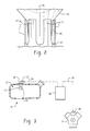
- FIG. 1 is a cross-section of the valve of the present invention installed in the upper wall of a fuel tank;
- FIG. 2 is an enlarged section view taken along section-indicating lines 2-2 of FIG. 1; and,
- FIG. 3 is a pictorial representation of a system employing the valve of the present invention.
-
- Referring to FIGS. 1 and 3, the valve assembly of the present invention is indicated generally at 10 and is installed through an access opening 12 formed in the
top wall 14 of a fuel tank indicated generally at 16 and retained thereon by a cover or retainingmember 18 which may be attached to the tank either by fasteners or preferably weldment.Member 18 includes avent passage 20 which communicates through a preferably integrally formed fitting 22 with aconduit 24 which is connected thereto and connected to afuel storage reservoir 26 as indicated by dashed outline in FIG. 3. Reservoir 26 has anotherconduit 28 connecting the reservoir to theair inlet 30 of amotor vehicle engine 31. - Referring to FIG. 1, the
valve 10 includes ahousing 32 connected to abody 33 by snaplocking housing slots 37 overtabs 35 provided on thebody 33 having the exterior thereof adapted to be received through thetank aperture 12 in closely fitting arrangement. The upper end of the valve body has anannular flange 34 formed thereon for registering on the upper surface of the tank about theaccess hole 12. Thecover 18 is received over theflange 34 and the cover is sealed on the valve body by asuitable seal ring 36 or any other suitable expedient and is secured to thetank top 14, preferably by weldment. - The upper end of the
housing 32 is closed and has formed therein anannular valve seat 38 which communicates withvent passage 20 in the cover. - A
float 46 is disposed inbody 33; and, the lower end of the float has a reduceddiameter portion 48. Thebody 33 has an annularinner wall 42 which forms a guide bore and has anannular rib 44 formed thereabout for providing a guide surface forfloat portion 48. - Referring to FIG. 2 the upper end of
annular wall 42 is castellated to form a plurality of resilient axially extendingfingers 47 circumferentially spaced about theannular wall 42 and which are radially resiliently deflectable.Float member 46 is thus slidably received in thehousing 32. Thefloat 46 has an annular axiallytapered surface 50 formed between thediameter 48 and theupper portion 46, which tapered portion contacts the ends offingers 47 when the float is lowered. Thefingers 47 thus resiliently and silently arrest the downward motion of the float. - The upper end of the
float 46 has atapered pintle 52 formed thereon for sealing againstvalve seat 38 when the fuel level in the tank has reached a predetermined level and has raised the float. - A
calibration plate 52 is provided in the bottom of the housing; and, a calibration spring has the lower end thereof registered againstplate 52 and the upper end registered in agroove 54 formed in the float.Plate 52 is adjusted in anannular groove 60 formed in the body to provide a desired positioning of thepintle 52 of the float with respect tovalve seat 38 such that the buoyant force of the liquid fuel in the tank at the predetermined level will cause thefloat pintle 52 to seat on thevalve seat 38closing vent passage 20. -
Slots 58 are formed in the side ofhousing 32 thereof to insure entrance of the liquid fuel to the float chamber. - The present invention thus provides a float operated fuel vapor vent valve for a fuel tank which has the stop for the lower travel limit of the float provided with resilient surfaces to silently arrest the downward movement of the float, thereby preventing rattling and undesirable noise due to sloshing of the fuel in the tank or motion of the vehicle.
- Although the invention has hereinabove been described with respect to the illustrated embodiments, it will be understood that the invention is capable of modification and variation and is limited only by the following claims.
Claims (7)
- An on-board refueling vapor recovery valve (ORVR) for use in a motor vehicle fuel tank comprising:(a) housing structure defining a float chamber with an outlet wherein said float is operative upon encountering a first predetermined level of liquid fuel in the fuel tank to move to a position closing said outlet with an upper end of said float and to move to a position opening said outlet when fuel level falls below said first level and when said float is moved to a position contacting said body with a lower end of said float upon fuel dropping below a second level lower than said first;(b) means for dampening movement of said float upon contacting said body; and,(c) means applying a force to bias said float in a direction toward said closed position.
- The valve defined in claim 1, wherein said means for dampening comprises a plurality of resilient fingers disposed about said float, said fingers making contact with said float during said moving to said position contacting said body and said fingers are resiliently deflected by said float.
- The valve defined in claim 1, wherein said means for dampening includes resilient portions of said body formed in said float chamber.
- The valve defined in claim 1, wherein said means for dampening includes a plurality of resilient fingers disposed about said float and said float includes a tapered surface contacting said fingers during said moving.
- A method of quieting an on-board vapor valve for use in a motor vehicle fuel tank comprising:(a) forming a float chamber in a valve body and disposing a float in said chamber and disposing the valve body on the fuel tank;(b) forming a fuel vapor outlet in said chamber and moving said float to close said outlet when fuel rises above a predetermined first level in the tank; and, moving said float away from said outlet when fuel falls below said first level and contacting said body with said float when fuel fills below a second level lower than said first;(c) disposing a resilient dampener in said float chamber and contacting said dampener upon said float reaching said second level and absorbing at least a portion of the energy of float movement.
- The method defined in claim 5, wherein said step of disposing a resilient dampener includes forming a plurality of resilient fingers in said float chamber and deflecting said fingers during said moving.
- The method defined in claim 5, wherein said step of disposing a dampener includes forming a plurality of resilient fingers in said float chamber and forming a tapered surface on said float.
Applications Claiming Priority (2)
| Application Number | Priority Date | Filing Date | Title |
|---|---|---|---|
| US09/726,234 US6405766B1 (en) | 2000-11-29 | 2000-11-29 | Noise dampened float type fuel vapor vent valve |
| US726234 | 2000-11-29 |
Publications (2)
| Publication Number | Publication Date |
|---|---|
| EP1221566A1 true EP1221566A1 (en) | 2002-07-10 |
| EP1221566B1 EP1221566B1 (en) | 2004-03-31 |
Family
ID=24917731
Family Applications (1)
| Application Number | Title | Priority Date | Filing Date |
|---|---|---|---|
| EP01127917A Expired - Lifetime EP1221566B1 (en) | 2000-11-29 | 2001-11-23 | Noise dampened float type fuel vapor vent valve |
Country Status (4)
| Country | Link |
|---|---|
| US (1) | US6405766B1 (en) |
| EP (1) | EP1221566B1 (en) |
| DE (1) | DE60102551T2 (en) |
| ES (1) | ES2217078T3 (en) |
Families Citing this family (25)
| Publication number | Priority date | Publication date | Assignee | Title |
|---|---|---|---|---|
| IL131052A (en) * | 1999-07-23 | 2002-02-10 | Raviv Prec Injection Molding | Silenced valve |
| US6863082B1 (en) * | 2003-08-13 | 2005-03-08 | Eaton Corporation | Mounting a fuel vapor management valve internally to a gas tank |
| US20070000542A1 (en) * | 2005-06-30 | 2007-01-04 | Ti Group Automotive Systems, L.L.C. | Fuel tank valve |
| ITMI20072138A1 (en) * | 2007-11-08 | 2009-05-09 | Rpe Srl | FLOW INTERCEPT VALVE |
| KR101603296B1 (en) | 2008-04-23 | 2016-03-14 | 시그노드 인터내셔널 아이피 홀딩스 엘엘씨 | Moblie strapping device |
| CN102026873B (en) | 2008-04-23 | 2016-05-18 | 信诺国际Ip控股有限责任公司 | With the knot installation of electronic driver |
| US10518914B2 (en) | 2008-04-23 | 2019-12-31 | Signode Industrial Group Llc | Strapping device |
| EP2280875B1 (en) | 2008-04-23 | 2012-05-16 | Orgapack GmbH | Strapping device with a gear system device |
| CN201411058Y (en) * | 2008-04-23 | 2010-02-24 | 奥格派克有限公司 | Strapping equipment provided with tension unit |
| CN102046472B (en) | 2008-04-23 | 2016-04-06 | 信诺国际Ip控股有限责任公司 | With the knot installation of accumulator |
| US11999516B2 (en) | 2008-04-23 | 2024-06-04 | Signode Industrial Group Llc | Strapping device |
| CH705743A2 (en) | 2011-11-14 | 2013-05-15 | Illinois Tool Works | Strapper. |
| KR101300925B1 (en) * | 2011-11-28 | 2013-08-27 | 주식회사 동희산업 | Noise Protective type Vent Valve for Fuel Tank |
| US9938029B2 (en) | 2012-09-24 | 2018-04-10 | Signode Industrial Group Llc | Strapping device having a pivotable rocker |
| CH708294A2 (en) | 2013-05-05 | 2014-12-15 | Orgapack Gmbh | Strapper. |
| US10689140B2 (en) | 2014-02-10 | 2020-06-23 | Signode Industrial Group Llc | Strapping apparatus |
| WO2017147004A1 (en) | 2016-02-25 | 2017-08-31 | Donaldson Company, Inc. | Liquid reservoir shutoff vent |
| US10060544B2 (en) | 2016-02-29 | 2018-08-28 | Ford Global Technologies, Llc | Noise attenuated fill limit vent valve |
| USD864688S1 (en) | 2017-03-28 | 2019-10-29 | Signode Industrial Group Llc | Strapping device |
| US11174051B2 (en) | 2019-02-15 | 2021-11-16 | Samuel, Son & Co. (Usa) Inc. | Hand held strapping tool |
| US11885493B2 (en) | 2020-09-16 | 2024-01-30 | Field Controls, Llc | Flue damper with a drainage port |
| US11703221B2 (en) | 2020-09-16 | 2023-07-18 | Field Controls, L.L.C. | Flue damper having a float coupled to a damper gate |
| CN116745516B (en) * | 2021-02-02 | 2026-05-15 | 百乐仕株式会社 | Valve device |
| US11738990B2 (en) * | 2021-06-16 | 2023-08-29 | Whitecap Industries, Inc. | Ullage float assembly for fuel tank and methods of use |
| US12397943B2 (en) | 2022-11-29 | 2025-08-26 | Samuel, Son & Co. (Usa) Inc. | Handheld strapping device |
Citations (4)
| Publication number | Priority date | Publication date | Assignee | Title |
|---|---|---|---|---|
| US5605177A (en) * | 1993-08-30 | 1997-02-25 | Toyoda Gosei Co., Ltd. | Fuel reservoir apparatus |
| US5711339A (en) * | 1996-01-08 | 1998-01-27 | Nifco Inc. | Fuel outflow preventing valve device |
| US5901733A (en) * | 1996-01-31 | 1999-05-11 | Nissan Motor Co., Ltd. | Valve for detecting liquid surface |
| WO2001007807A1 (en) * | 1999-07-23 | 2001-02-01 | Raval - Agricultural Cooperative Societies Ltd. | Silenced valve |
Family Cites Families (2)
| Publication number | Priority date | Publication date | Assignee | Title |
|---|---|---|---|---|
| GB1451437A (en) * | 1972-11-09 | 1976-10-06 | Bridgemore Eng Ltd | Air bleeding device for a pressurised lqiuid supply system |
| US5590697A (en) * | 1994-08-24 | 1997-01-07 | G. T. Products, Inc. | Onboard vapor recovery system with two-stage shutoff valve |
-
2000
- 2000-11-29 US US09/726,234 patent/US6405766B1/en not_active Expired - Lifetime
-
2001
- 2001-11-23 EP EP01127917A patent/EP1221566B1/en not_active Expired - Lifetime
- 2001-11-23 ES ES01127917T patent/ES2217078T3/en not_active Expired - Lifetime
- 2001-11-23 DE DE60102551T patent/DE60102551T2/en not_active Expired - Lifetime
Patent Citations (4)
| Publication number | Priority date | Publication date | Assignee | Title |
|---|---|---|---|---|
| US5605177A (en) * | 1993-08-30 | 1997-02-25 | Toyoda Gosei Co., Ltd. | Fuel reservoir apparatus |
| US5711339A (en) * | 1996-01-08 | 1998-01-27 | Nifco Inc. | Fuel outflow preventing valve device |
| US5901733A (en) * | 1996-01-31 | 1999-05-11 | Nissan Motor Co., Ltd. | Valve for detecting liquid surface |
| WO2001007807A1 (en) * | 1999-07-23 | 2001-02-01 | Raval - Agricultural Cooperative Societies Ltd. | Silenced valve |
Also Published As
| Publication number | Publication date |
|---|---|
| US6405766B1 (en) | 2002-06-18 |
| EP1221566B1 (en) | 2004-03-31 |
| ES2217078T3 (en) | 2004-11-01 |
| DE60102551T2 (en) | 2005-04-14 |
| DE60102551D1 (en) | 2004-05-06 |
Similar Documents
| Publication | Publication Date | Title |
|---|---|---|
| US6405766B1 (en) | Noise dampened float type fuel vapor vent valve | |
| US6941966B2 (en) | Outflow-limiting device of fuel tank | |
| EP1705051B1 (en) | Low profile overfill limit device with reverse flow capability | |
| JP5265262B2 (en) | Float valve device | |
| JP3034992B2 (en) | Fuel cut-off device for fuel tank | |
| US6085771A (en) | Two-stage fuel tank vapor recovery vent valve and method of making same | |
| US7934514B2 (en) | Fuel cutoff valve | |
| US20040149333A1 (en) | Vapor vent valve | |
| EP1617113B1 (en) | Fuel vapor vent valve float assembly and method of making same | |
| US20040055638A1 (en) | Apparatus for inhibiting fuels from flowing out of fuel tanks | |
| US6708713B1 (en) | Fill limit control valve assembly having a liquid fuel trap | |
| EP0238160A2 (en) | Roll-over valve | |
| US5924438A (en) | Gas-pressure relief valve unit, particularly for fuel vapors | |
| JPH04236870A (en) | Fuel vapor relief valve | |
| KR19990087909A (en) | Installing a fill limiting vent valve in a fuel tank | |
| US5775362A (en) | Fuel-effusion prevention valve | |
| EP1300579A2 (en) | Fuel tank ventilation valve for internal combustion engines | |
| EP1124083B1 (en) | Vapour venting valve in a fuel tank | |
| US20070000542A1 (en) | Fuel tank valve | |
| US8490642B2 (en) | Fuel-outflow check valve | |
| US7146729B2 (en) | Fuel vapor vent valve and method of attaching same to a tank | |
| JP5949686B2 (en) | In-tank valve unit | |
| US5954083A (en) | Liquid flow-out prevention valve | |
| JP4207875B2 (en) | Fuel shut-off valve | |
| JP3131763B2 (en) | Stop valve structure |
Legal Events
| Date | Code | Title | Description |
|---|---|---|---|
| PUAI | Public reference made under article 153(3) epc to a published international application that has entered the european phase |
Free format text: ORIGINAL CODE: 0009012 |
|
| AK | Designated contracting states |
Kind code of ref document: A1 Designated state(s): AT BE CH CY DE DK ES FI FR GB GR IE IT LI LU MC NL PT SE TR |
|
| AX | Request for extension of the european patent |
Free format text: AL;LT;LV;MK;RO;SI |
|
| 17P | Request for examination filed |
Effective date: 20021216 |
|
| AKX | Designation fees paid |
Designated state(s): DE FR GB IT SE |
|
| RBV | Designated contracting states (corrected) |
Designated state(s): DE ES FR GB IT |
|
| 17Q | First examination report despatched |
Effective date: 20030306 |
|
| GRAP | Despatch of communication of intention to grant a patent |
Free format text: ORIGINAL CODE: EPIDOSNIGR1 |
|
| GRAS | Grant fee paid |
Free format text: ORIGINAL CODE: EPIDOSNIGR3 |
|
| GRAA | (expected) grant |
Free format text: ORIGINAL CODE: 0009210 |
|
| AK | Designated contracting states |
Kind code of ref document: B1 Designated state(s): DE ES FR GB IT |
|
| REG | Reference to a national code |
Ref country code: GB Ref legal event code: FG4D |
|
| REG | Reference to a national code |
Ref country code: IE Ref legal event code: FG4D |
|
| REF | Corresponds to: |
Ref document number: 60102551 Country of ref document: DE Date of ref document: 20040506 Kind code of ref document: P |
|
| REG | Reference to a national code |
Ref country code: ES Ref legal event code: FG2A Ref document number: 2217078 Country of ref document: ES Kind code of ref document: T3 |
|
| ET | Fr: translation filed | ||
| PLBE | No opposition filed within time limit |
Free format text: ORIGINAL CODE: 0009261 |
|
| STAA | Information on the status of an ep patent application or granted ep patent |
Free format text: STATUS: NO OPPOSITION FILED WITHIN TIME LIMIT |
|
| 26N | No opposition filed |
Effective date: 20050104 |
|
| PGFP | Annual fee paid to national office [announced via postgrant information from national office to epo] |
Ref country code: FR Payment date: 20051104 Year of fee payment: 5 |
|
| PGFP | Annual fee paid to national office [announced via postgrant information from national office to epo] |
Ref country code: ES Payment date: 20051123 Year of fee payment: 5 |
|
| PGFP | Annual fee paid to national office [announced via postgrant information from national office to epo] |
Ref country code: IT Payment date: 20061130 Year of fee payment: 6 |
|
| GBPC | Gb: european patent ceased through non-payment of renewal fee |
Effective date: 20061123 |
|
| REG | Reference to a national code |
Ref country code: FR Ref legal event code: ST Effective date: 20070731 |
|
| PG25 | Lapsed in a contracting state [announced via postgrant information from national office to epo] |
Ref country code: GB Free format text: LAPSE BECAUSE OF NON-PAYMENT OF DUE FEES Effective date: 20061123 |
|
| REG | Reference to a national code |
Ref country code: ES Ref legal event code: FD2A Effective date: 20061124 |
|
| PG25 | Lapsed in a contracting state [announced via postgrant information from national office to epo] |
Ref country code: FR Free format text: LAPSE BECAUSE OF NON-PAYMENT OF DUE FEES Effective date: 20061130 Ref country code: ES Free format text: LAPSE BECAUSE OF NON-PAYMENT OF DUE FEES Effective date: 20061124 |
|
| PGFP | Annual fee paid to national office [announced via postgrant information from national office to epo] |
Ref country code: GB Payment date: 20051004 Year of fee payment: 5 |
|
| PG25 | Lapsed in a contracting state [announced via postgrant information from national office to epo] |
Ref country code: IT Free format text: LAPSE BECAUSE OF NON-PAYMENT OF DUE FEES Effective date: 20071123 |
|
| REG | Reference to a national code |
Ref country code: DE Ref legal event code: R082 Ref document number: 60102551 Country of ref document: DE Ref country code: DE Ref legal event code: R081 Ref document number: 60102551 Country of ref document: DE Owner name: EATON INTELLIGENT POWER LIMITED, IE Free format text: FORMER OWNER: EATON CORP., CLEVELAND, OHIO, US |
|
| PGFP | Annual fee paid to national office [announced via postgrant information from national office to epo] |
Ref country code: DE Payment date: 20201020 Year of fee payment: 20 |
|
| REG | Reference to a national code |
Ref country code: DE Ref legal event code: R071 Ref document number: 60102551 Country of ref document: DE |
|
| P01 | Opt-out of the competence of the unified patent court (upc) registered |
Effective date: 20230521 |