EP1221560A2 - Engine for a vehicle - Google Patents
Engine for a vehicle Download PDFInfo
- Publication number
- EP1221560A2 EP1221560A2 EP02000355A EP02000355A EP1221560A2 EP 1221560 A2 EP1221560 A2 EP 1221560A2 EP 02000355 A EP02000355 A EP 02000355A EP 02000355 A EP02000355 A EP 02000355A EP 1221560 A2 EP1221560 A2 EP 1221560A2
- Authority
- EP
- European Patent Office
- Prior art keywords
- engine
- crankshaft
- transmitting means
- auxiliary machine
- driving
- Prior art date
- Legal status (The legal status is an assumption and is not a legal conclusion. Google has not performed a legal analysis and makes no representation as to the accuracy of the status listed.)
- Granted
Links
Images


Classifications
-
- F—MECHANICAL ENGINEERING; LIGHTING; HEATING; WEAPONS; BLASTING
- F02—COMBUSTION ENGINES; HOT-GAS OR COMBUSTION-PRODUCT ENGINE PLANTS
- F02B—INTERNAL-COMBUSTION PISTON ENGINES; COMBUSTION ENGINES IN GENERAL
- F02B75/00—Other engines
- F02B75/16—Engines characterised by number of cylinders, e.g. single-cylinder engines
-
- F—MECHANICAL ENGINEERING; LIGHTING; HEATING; WEAPONS; BLASTING
- F01—MACHINES OR ENGINES IN GENERAL; ENGINE PLANTS IN GENERAL; STEAM ENGINES
- F01P—COOLING OF MACHINES OR ENGINES IN GENERAL; COOLING OF INTERNAL-COMBUSTION ENGINES
- F01P5/00—Pumping cooling-air or liquid coolants
- F01P5/10—Pumping liquid coolant; Arrangements of coolant pumps
- F01P5/12—Pump-driving arrangements
-
- F—MECHANICAL ENGINEERING; LIGHTING; HEATING; WEAPONS; BLASTING
- F02—COMBUSTION ENGINES; HOT-GAS OR COMBUSTION-PRODUCT ENGINE PLANTS
- F02B—INTERNAL-COMBUSTION PISTON ENGINES; COMBUSTION ENGINES IN GENERAL
- F02B61/00—Adaptations of engines for driving vehicles or for driving propellers; Combinations of engines with gearing
- F02B61/02—Adaptations of engines for driving vehicles or for driving propellers; Combinations of engines with gearing for driving cycles
-
- F—MECHANICAL ENGINEERING; LIGHTING; HEATING; WEAPONS; BLASTING
- F16—ENGINEERING ELEMENTS AND UNITS; GENERAL MEASURES FOR PRODUCING AND MAINTAINING EFFECTIVE FUNCTIONING OF MACHINES OR INSTALLATIONS; THERMAL INSULATION IN GENERAL
- F16F—SPRINGS; SHOCK-ABSORBERS; MEANS FOR DAMPING VIBRATION
- F16F15/00—Suppression of vibrations in systems; Means or arrangements for avoiding or reducing out-of-balance forces, e.g. due to motion
- F16F15/22—Compensation of inertia forces
- F16F15/26—Compensation of inertia forces of crankshaft systems using solid masses, other than the ordinary pistons, moving with the system, i.e. masses connected through a kinematic mechanism or gear system
- F16F15/264—Rotating balancer shafts
- F16F15/268—Hollow shafts
-
- F—MECHANICAL ENGINEERING; LIGHTING; HEATING; WEAPONS; BLASTING
- F01—MACHINES OR ENGINES IN GENERAL; ENGINE PLANTS IN GENERAL; STEAM ENGINES
- F01P—COOLING OF MACHINES OR ENGINES IN GENERAL; COOLING OF INTERNAL-COMBUSTION ENGINES
- F01P2050/00—Applications
- F01P2050/16—Motor-cycles
-
- F—MECHANICAL ENGINEERING; LIGHTING; HEATING; WEAPONS; BLASTING
- F02—COMBUSTION ENGINES; HOT-GAS OR COMBUSTION-PRODUCT ENGINE PLANTS
- F02B—INTERNAL-COMBUSTION PISTON ENGINES; COMBUSTION ENGINES IN GENERAL
- F02B75/00—Other engines
- F02B75/02—Engines characterised by their cycles, e.g. six-stroke
- F02B2075/022—Engines characterised by their cycles, e.g. six-stroke having less than six strokes per cycle
- F02B2075/027—Engines characterised by their cycles, e.g. six-stroke having less than six strokes per cycle four
-
- F—MECHANICAL ENGINEERING; LIGHTING; HEATING; WEAPONS; BLASTING
- F02—COMBUSTION ENGINES; HOT-GAS OR COMBUSTION-PRODUCT ENGINE PLANTS
- F02B—INTERNAL-COMBUSTION PISTON ENGINES; COMBUSTION ENGINES IN GENERAL
- F02B2275/00—Other engines, components or details, not provided for in other groups of this subclass
- F02B2275/18—DOHC [Double overhead camshaft]
-
- F—MECHANICAL ENGINEERING; LIGHTING; HEATING; WEAPONS; BLASTING
- F02—COMBUSTION ENGINES; HOT-GAS OR COMBUSTION-PRODUCT ENGINE PLANTS
- F02F—CYLINDERS, PISTONS OR CASINGS, FOR COMBUSTION ENGINES; ARRANGEMENTS OF SEALINGS IN COMBUSTION ENGINES
- F02F1/00—Cylinders; Cylinder heads
- F02F1/24—Cylinder heads
- F02F2001/244—Arrangement of valve stems in cylinder heads
- F02F2001/245—Arrangement of valve stems in cylinder heads the valve stems being orientated at an angle with the cylinder axis
Definitions
- the present invention relates to an engine for a vehicle, in particular a motorcycle in which an auxiliary machine is driven by a crankshaft.
- an input shaft of an auxiliary machine such as an oil pump and a cooling water pump is connected to a crankshaft via a chain.
- the input shaft is supported by a crankcase such that it is in parallel with the crankshaft, and has one end part which is connected to, for example, the oil pump and the other end part on which a sprocket is fixed.
- the chain is trained between the sprocket and a sprocket integrally formed with the crankshaft.
- a gear for driving a balancer In addition to the sprocket for driving the auxiliary machine, there are provided on the crankshaft a gear for driving a balancer, a gear in meshing engagement with a starter, a sprocket over which a cam chain is trained and so on.
- the present invention has been made to overcome the drawbacks and it is, therefore, an object of the present invention to shorten the overall length of the crankshaft while employing a structure in which an auxiliary machine is driven by the crankshaft.
- an engine for a vehicle in particular a motorcycle, comprising a crankshaft, a balancer and at least one auxiliary machine, wherein a transmitting means in association with the balancer is provided for transmitting a rotation of the crankshaft to the at least one auxiliary machine.
- the auxiliary machine can be driven utilizing the balancer, which is one of the component parts of the engine, there is no need to form a sprocket for exclusively driving the auxiliary machine so that the number of the sprockets to be formed on the crankshaft can be reduced.
- the overall length of the crankshaft is beneficially shortened.
- the balancer is geared to the crankshaft.
- the auxiliary machine beneficially comprises an oil pump or a cooling water pump or a fuel pump.
- the transmitting means can comprise an auxiliary machine driving transmitting means, in particular a chain, a belt or a gear.
- the transmitting means further comprises a driving shaft and an intermediate shaft, wherein the driving shaft and the intermediate shaft are geared to each other through gears, and wherein the balancer is connected to the intermediate shaft by the auxiliary machine driving transmitting means.
- the engine further comprises a camshaft and a camshaft driving transmitting means for transmitting the rotation of the crankshaft to the camshaft in a direction of an axis of the crankshaft, wherein the auxiliary machine driving transmitting means is arranged substantially in the same position in the vehicle width direction as a camshaft driving transmitting means and extends in a direction perpendicular to said axis of said crankshaft.
- the camshaft driving transmitting means comprises a cam chain.
- auxiliary machine driving transmitting means is arranged to extend through a dead space D located behind the cam chain.
- the engine is a unit swing type, water-cooled, four-cycle single-cylinder engine and/or the vehicle is constituted by a scooter type motorcycle.
- the engine for a motorcycle has the features that a balancer is geared with a crankshaft, that an auxiliary machine is connected to the balancer via the auxiliary machine-driving transmitting means, that the auxiliary machine-driving transmitting means is arranged in the same position as the camshaft-driving transmitting means for transmitting rotation of the crankshaft to a camshaft in the direction of an axis of the crankshaft and extends in a direction perpendicular to the axis of the crankshaft.
- the crankcase is not increased in size in the vehicle width direction to provide the auxiliary machine-driving transmitting means.
- Fig. 1 is a side view of a motorcycle mounting an engine according to the present embodiment.
- Fig. 2 is a plan view of the engine for a motorcycle according to the present embodiment, wherein a crankshaft part is broken away.
- Fig. 3 is a left side view the engine for a motorcycle according to the present embodiment, wherein a crankcase and a part of cylinder are broken away.
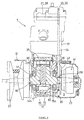
- Fig. 4 is a right side view of the engine for a motorcycle according to the present embodiment, broken way so that a chain chamber may be exposed.
- Fig. 5 is a cross-sectional view of the crankshaft and a balancer taken along the line V-V of Fig. 3.
- Fig. 6 is a cross-sectional view of an oil pump portion taken along the line VI-VI of in Fig. 4.
- a scooter-type motorcycle designated as 1 is a scooter-type motorcycle according to this embodiment.
- Fig. 1 designated as 2 is a body frame, as 3 is a front fork, as 4 is a front wheel, as 5 is a steering handle, as 6 is a seat, as 7 is an engine according to the present embodiment, and as 8 is a rear wheel.
- the engine 7 is a unit swing type, water-cooled, four-cycle single-cylinder engine, wherein a transmission case 12 in integrally formed with a crankcase 11.
- the engine 7 is supported on the body frame 2 for vertical swinging movement such that an axis of a cylinder 13 is inclined upward toward the front of the vehicle.
- the transmission case 12 has a rear end part on which a rear wheel 8 is rotatably supported.
- crankcase 11 can be separated in the vehicle width direction into a left half part 14 and a right half part 15.
- the left half part 14 and the right half part 15 have side walls 14a and 15a, respectively, on which a crankshaft 16 is rotatably supported via bearings 17 and 18.
- an oil pan 21 is formed at a lower end part of the crankcase 11.
- the left half part 14 of the crankcase 11 has a left end part to which a transmission case cover (not shown) is fixed and constitutes a transmission case 12 together with the transmission cover.
- a transmission case cover (not shown) is fixed and constitutes a transmission case 12 together with the transmission cover.
- a V-belt automatic transmission 22 mounted on the left side end of the crankshaft 16.
- the right half part 15 of the crankcase 11 has a right end part to which a crankcase cover 23 is fixed. As shown in Fig. 4, a space S between the right haft part 15 and the crankcase cover 23 is connected to a chain chamber 25 of the cylinder 13 accommodating a cam chain 24.
- the cam chain 24 is trained over a sprocket 26 for the cam chain integrally formed with the crankshaft 16 and camshaft side sprockets 29 and 30 fixed on an intake camshaft 27 and an exhaust camshaft 28, respectively.
- the cam chain 24 constitutes the camshaft-driving transmitting means according to the present embodiment.
- the engine 7 is a so-called DOHC type, which has the intake camshaft 27 and the exhaust camshaft 28, and employs a valve operating device 34 in which the camshafts 27 and 28 drive an intake valve 32 and an exhaust valve 33, respectively, each via a valve lifter 31 as shown in Fig. 3.
- Fig. 3 designated as 35 is a piston, and as 36 is a connecting rod.
- a flywheel magneto 41 provided on the right side end of the crankshaft 16
- a gear 42 for a starter and an oil pump 43 (see Fig. 4).
- the oil pump 43 constitutes the auxiliary machine according to the present embodiment.
- the gear 42 for the starter is fixed on the crankshaft 16, between the sprocket 26 for the cam chain and the flywheel magneto 41, and in meshing engagement with a starter motor (not shown).
- the oil pump 43 has a pump housing 44 accommodating a rotor 45 and is fixed on the side wall 15a.
- a rotor 45 When the rotor 45 is rotated, oil in the oil pan 21 is sucked up through a straighter 46 and fed to parts to be lubricated or cooled thereby.
- the rotor 45 is fixed on a driving shaft 47 extending through the side wall 15a and toward the inside of the vehicle body. The rotation of the crankshaft 16 is transmitted to the rotor 45 by transmitting means 51 having the driving shaft 47.
- the transmitting means 51 comprises the driving shaft 47, an intermediate shaft 54 geared with the driving shaft 47 via gears 52 and 53, a balancer 56 connected to the intermediate shaft 54 via an oil pump driving chain 55 and so on.
- the oil pump driving chain 55 constitutes the auxiliary machine-driving transmitting means according to the present embodiment.
- the intermediate shaft 54 is rotatably supported by the side wall 15a of the right half part 15 of the crankcase 11 and has one end part which extends toward the inside of the vehicle body from the side wall 15a and on which the gear 53 is fixed and the other end part which extends toward the outside of the vehicle body from the side wall 15a and on which a driven sprocket 57 for the oil pump driving chain 55 is fixed.
- the balancer 56 is a device for reducing vibration by a constitution similar to that of a conventionally well-known device, wherein, as shown in Fig. 5, a weight 58 arranged between webs 16a and 16b of the crankshaft 16 is integrally formed with a shaft.59, which is arranged in parallel with the crankshaft 16 and rotatably supported by the crankcase 11 via bearings 60 and 61.
- the balancer 56 is geared with the crankshaft 16 via gears 62 and 63.
- the shaft 59 of the balancer 56 has a right end part which is protruded sideward from the bearing 61 and on which a driving sprocket 64 over which the oil pump driving chain 55 is trained is fixed.
- the protruded end of the shaft 59 is connected to an input shaft 66 of a cooling water pump 65.
- the cooling water pump 65 is for supplying cooling water to the engine 7 and supported by the crankcase cover 23.
- the balancer 56 is arranged above and behind the crankshaft 16.
- the intermediate shaft 54 connected to the balancer 56 via the oil pump driving chain 55 is arranged below and behind the crankshaft 16 as shown in Fig. 4.
- the positions of the intermediate shaft 54 and the balancer 56 are so determined that the oil pump driving chain 55 connecting these extends in a direction perpendicular to the axis of the crankshaft 16 and downward toward the rear behind the cam chain 24 as shown in Fig. 4.
- the oil pump driving chain 55 is arranged to extend through a dead space D (see Fig. 2) formed behind the cam chain 24.
- the oil pump driving chain 55 can be arranged in the same position as the cam chain 24 in the vehicle width direction utilizing the dead space D formed behind the cam chain 24 so that the crankcase 11 is not increased in size in the vehicle width direction to provide the oil pump driving chain 55.
- the overall length of the crankshaft 16 can be shortened so that the motorcycle 1 mounting the engine 7 is allowed to take a large bank angle. Additionally, when the crankshaft 16 is shortened, the resonant rotation speed thereof can be separated away from its normal rotation speed range so that noise can be reduced and occurrence of problems concerning strength can be avoided.
- auxiliary machine is the oil pump
- teaching of the present embodiment need not be limited to the above embodiment but is applicable to other auxiliary machines such as a cooling water pump and a fuel pump for a fuel injection device in place of the oil pump.
- a belt or a gear may be employed instead of the chain.
- the auxiliary machine can be driven utilizing the balancer, which is one of the component parts of the engine.
- the balancer which is one of the component parts of the engine.
- the auxiliary machine-driving transmitting means can be arranged in the same position as the camshaft-driving transmitting means in the vehicle width direction utilizing the dead space formed around the camshaft-driving transmitting means, the crankcase is not increased in size in the vehicle width direction to provide the auxiliary machine-driving transmitting means.
- the engine since the overall length of the crankshaft can be shortened by employing the structure in which the auxiliary machine is driven by the crankshaft, the engine can be reduced in size in the vehicle width direction as compared with a conventional engine.
- a motorcycle mounting the engine according to the present embodiment is allowed to take a large bank angle. Additionally, since the resonant rotation speed of the crankshaft can be separated away from the normal rotation speed range thereof by shortening the crankshaft, noise can be reduced and occurrence of problems concerning strength can be avoided.
- the engine for a motorcycle is characterized in that a balancer is geared with a crankshaft, that an auxiliary machine is connected to said balancer via auxiliary machine-driving transmitting means, that said auxiliary machine-driving transmitting means is arranged in the same position as camshaft-driving transmitting means for transmitting rotation of said crankshaft to a camshaft in the direction of an axis of said crankshaft and extends in a direction perpendicular to said axis of said crankshaft.
- the balancer 56 is geared with a crankshaft 16.
- An oil pump 43 is connected to the balancer 56 via an oil pump driving chain 55.
- the oil pump driving chain 55 is arranged in the same position as a cam chain 24 in the direction of an axis of the crankshaft 16 and extends in a direction perpendicular to the axis of the crankshaft 16.
- crankshaft Due to this structure, the overall length of a crankshaft is beneficially shortened while employing a structure in which an auxiliary machine is driven by the crankshaft.
Landscapes
- Engineering & Computer Science (AREA)
- General Engineering & Computer Science (AREA)
- Mechanical Engineering (AREA)
- Chemical & Material Sciences (AREA)
- Combustion & Propulsion (AREA)
- Physics & Mathematics (AREA)
- Acoustics & Sound (AREA)
- Aviation & Aerospace Engineering (AREA)
- Lubrication Of Internal Combustion Engines (AREA)
- Shafts, Cranks, Connecting Bars, And Related Bearings (AREA)
- Devices For Conveying Motion By Means Of Endless Flexible Members (AREA)
Abstract
Description
- The present invention relates to an engine for a vehicle, in particular a motorcycle in which an auxiliary machine is driven by a crankshaft.
- In a conventional engine for a motorcycle of this type, an input shaft of an auxiliary machine such as an oil pump and a cooling water pump is connected to a crankshaft via a chain. The input shaft is supported by a crankcase such that it is in parallel with the crankshaft, and has one end part which is connected to, for example, the oil pump and the other end part on which a sprocket is fixed. The chain is trained between the sprocket and a sprocket integrally formed with the crankshaft.
- In addition to the sprocket for driving the auxiliary machine, there are provided on the crankshaft a gear for driving a balancer, a gear in meshing engagement with a starter, a sprocket over which a cam chain is trained and so on.
- In a conventional engine for a motorcycle constituted as above, many sprockets and gears are formed on the crankshaft so that the crankshaft is unavoidably long in length in the axis direction thereof. Thus, a motorcycle mounting such an engine has a problem of being unable to take a large bank angle. Also, when the crankshaft is long in length, the resonance rotation speed thereof is close to its normal rotation speed range so that there tend to occur problems concerning noise and strength.
- The present invention has been made to overcome the drawbacks and it is, therefore, an object of the present invention to shorten the overall length of the crankshaft while employing a structure in which an auxiliary machine is driven by the crankshaft.
- This objective is solved in an inventive manner by an engine for a vehicle, in particular a motorcycle, comprising a crankshaft, a balancer and at least one auxiliary machine, wherein a transmitting means in association with the balancer is provided for transmitting a rotation of the crankshaft to the at least one auxiliary machine.
- Since the auxiliary machine can be driven utilizing the balancer, which is one of the component parts of the engine, there is no need to form a sprocket for exclusively driving the auxiliary machine so that the number of the sprockets to be formed on the crankshaft can be reduced. Thus, the overall length of the crankshaft is beneficially shortened.
- It is preferable if the balancer is geared to the crankshaft.
- Also, the auxiliary machine beneficially comprises an oil pump or a cooling water pump or a fuel pump.
- Additionally, the transmitting means can comprise an auxiliary machine driving transmitting means, in particular a chain, a belt or a gear.
- According to a preferred embodiment, the transmitting means further comprises a driving shaft and an intermediate shaft, wherein the driving shaft and the intermediate shaft are geared to each other through gears, and wherein the balancer is connected to the intermediate shaft by the auxiliary machine driving transmitting means.
- According to another preferred embodiment, the engine further comprises a camshaft and a camshaft driving transmitting means for transmitting the rotation of the crankshaft to the camshaft in a direction of an axis of the crankshaft, wherein the auxiliary machine driving transmitting means is arranged substantially in the same position in the vehicle width direction as a camshaft driving transmitting means and extends in a direction perpendicular to said axis of said crankshaft.
- Within this embodiment, it is preferable if the camshaft driving transmitting means comprises a cam chain.
- It is further preferable if the auxiliary machine driving transmitting means is arranged to extend through a dead space D located behind the cam chain.
- According to a further preferred embodiment, the engine is a unit swing type, water-cooled, four-cycle single-cylinder engine and/or the vehicle is constituted by a scooter type motorcycle.
- According to yet another embodiment, the engine for a motorcycle has the features that a balancer is geared with a crankshaft, that an auxiliary machine is connected to the balancer via the auxiliary machine-driving transmitting means, that the auxiliary machine-driving transmitting means is arranged in the same position as the camshaft-driving transmitting means for transmitting rotation of the crankshaft to a camshaft in the direction of an axis of the crankshaft and extends in a direction perpendicular to the axis of the crankshaft.
- Since the auxiliary machine-driving transmitting means can be arranged in the same position as the camshaft-driving transmitting means in the vehicle width direction utilizing a dead space formed around the camshaft-driving transmitting means, the crankcase is not increased in size in the vehicle width direction to provide the auxiliary machine-driving transmitting means.
- In the following, the present invention is explained in greater detail with respect to several embodiments thereof in conjunction with the accompanying drawings, wherein:
- Fig. 1
- is a side view of a motorcycle mounting an engine according to an embodiment;
- Fig. 2
- is a plan view of the engine for a motorcycle according to this embodiment;
- Fig. 3
- is a left side view the engine for a motorcycle according to the present embodiment;
- Fig. 4
- is a right side view of the engine for a motorcycle according to the present embodiment;
- Fig. 5
- is a cross-sectional view of a crankshaft and a balancer taken along the line V-V of Fig. 3; and
- Fig. 6
- is a cross-sectional view of an oil pump portion taken along the line VI-VI of Fig. 4.
- Description will be hereinafter made in detail to the embodiment of an engine for a motorcycle with reference to Fig. 1 to Fig. 6.
- Fig. 1 is a side view of a motorcycle mounting an engine according to the present embodiment. Fig. 2 is a plan view of the engine for a motorcycle according to the present embodiment, wherein a crankshaft part is broken away. Fig. 3 is a left side view the engine for a motorcycle according to the present embodiment, wherein a crankcase and a part of cylinder are broken away. Fig. 4 is a right side view of the engine for a motorcycle according to the present embodiment, broken way so that a chain chamber may be exposed. Fig. 5 is a cross-sectional view of the crankshaft and a balancer taken along the line V-V of Fig. 3. Fig. 6 is a cross-sectional view of an oil pump portion taken along the line VI-VI of in Fig. 4.
- In the drawings, designated as 1 is a scooter-type motorcycle according to this embodiment. In Fig. 1, designated as 2 is a body frame, as 3 is a front fork, as 4 is a front wheel, as 5 is a steering handle, as 6 is a seat, as 7 is an engine according to the present embodiment, and as 8 is a rear wheel.
- The
engine 7 is a unit swing type, water-cooled, four-cycle single-cylinder engine, wherein atransmission case 12 in integrally formed with acrankcase 11. Theengine 7 is supported on the body frame 2 for vertical swinging movement such that an axis of acylinder 13 is inclined upward toward the front of the vehicle. Thetransmission case 12 has a rear end part on which a rear wheel 8 is rotatably supported. - As shown in Fig. 2, the
crankcase 11 can be separated in the vehicle width direction into aleft half part 14 and aright half part 15. Theleft half part 14 and theright half part 15 haveside walls crankshaft 16 is rotatably supported viabearings oil pan 21 is formed at a lower end part of thecrankcase 11. - The
left half part 14 of thecrankcase 11 has a left end part to which a transmission case cover (not shown) is fixed and constitutes atransmission case 12 together with the transmission cover. In thetransmission case 12 is accommodated a V-beltautomatic transmission 22 mounted on the left side end of thecrankshaft 16. - The
right half part 15 of thecrankcase 11 has a right end part to which acrankcase cover 23 is fixed. As shown in Fig. 4, a space S between theright haft part 15 and thecrankcase cover 23 is connected to achain chamber 25 of thecylinder 13 accommodating acam chain 24. Thecam chain 24 is trained over asprocket 26 for the cam chain integrally formed with thecrankshaft 16 andcamshaft side sprockets intake camshaft 27 and anexhaust camshaft 28, respectively. - The
cam chain 24 constitutes the camshaft-driving transmitting means according to the present embodiment. Theengine 7 is a so-called DOHC type, which has theintake camshaft 27 and theexhaust camshaft 28, and employs avalve operating device 34 in which thecamshafts intake valve 32 and anexhaust valve 33, respectively, each via avalve lifter 31 as shown in Fig. 3. In Fig. 3, designated as 35 is a piston, and as 36 is a connecting rod. - As shown in Fig. 2, in the space S formed between the
crankcase cover 23 and theright half part 15 of thecrankcase 11 are accommodated aflywheel magneto 41 provided on the right side end of thecrankshaft 16, agear 42 for a starter and an oil pump 43 (see Fig. 4). Theoil pump 43 constitutes the auxiliary machine according to the present embodiment. Thegear 42 for the starter is fixed on thecrankshaft 16, between thesprocket 26 for the cam chain and theflywheel magneto 41, and in meshing engagement with a starter motor (not shown). - As shown in Fig. 6, the
oil pump 43 has apump housing 44 accommodating arotor 45 and is fixed on theside wall 15a. When therotor 45 is rotated, oil in theoil pan 21 is sucked up through astraighter 46 and fed to parts to be lubricated or cooled thereby. Therotor 45 is fixed on adriving shaft 47 extending through theside wall 15a and toward the inside of the vehicle body. The rotation of thecrankshaft 16 is transmitted to therotor 45 by transmittingmeans 51 having thedriving shaft 47. - As shown in Fig. 6, the transmitting means 51 comprises the driving
shaft 47, anintermediate shaft 54 geared with the drivingshaft 47 viagears balancer 56 connected to theintermediate shaft 54 via an oilpump driving chain 55 and so on. The oilpump driving chain 55 constitutes the auxiliary machine-driving transmitting means according to the present embodiment. - The
intermediate shaft 54 is rotatably supported by theside wall 15a of the righthalf part 15 of thecrankcase 11 and has one end part which extends toward the inside of the vehicle body from theside wall 15a and on which thegear 53 is fixed and the other end part which extends toward the outside of the vehicle body from theside wall 15a and on which a drivensprocket 57 for the oilpump driving chain 55 is fixed. - The
balancer 56 is a device for reducing vibration by a constitution similar to that of a conventionally well-known device, wherein, as shown in Fig. 5, aweight 58 arranged betweenwebs crankshaft 16 is integrally formed with a shaft.59, which is arranged in parallel with thecrankshaft 16 and rotatably supported by thecrankcase 11 viabearings balancer 56 is geared with thecrankshaft 16 viagears - The
shaft 59 of thebalancer 56 has a right end part which is protruded sideward from thebearing 61 and on which a drivingsprocket 64 over which the oilpump driving chain 55 is trained is fixed. The protruded end of theshaft 59 is connected to aninput shaft 66 of acooling water pump 65. The coolingwater pump 65 is for supplying cooling water to theengine 7 and supported by thecrankcase cover 23. - As shown in Fig. 3, the
balancer 56 is arranged above and behind thecrankshaft 16. Theintermediate shaft 54 connected to thebalancer 56 via the oilpump driving chain 55 is arranged below and behind thecrankshaft 16 as shown in Fig. 4. The positions of theintermediate shaft 54 and thebalancer 56 are so determined that the oilpump driving chain 55 connecting these extends in a direction perpendicular to the axis of thecrankshaft 16 and downward toward the rear behind thecam chain 24 as shown in Fig. 4. Namely, in theengine 7, the oilpump driving chain 55 is arranged to extend through a dead space D (see Fig. 2) formed behind thecam chain 24. - In the
engine 7 for a motorcycle constituted as above, when thecrankshaft 16 is rotated, the rotation of thecrankshaft 16 is transmitted to theoil pump 43 viabalancer 56, the oilpump driving chain 55, theintermediate shaft 54 and thegears oil pump 43 can be driven utilizing thebalancer 56, which is one of the component parts of theengine 7. - Therefore, in the
engine 7, there is no need to form a sprocket for exclusively driving theoil pump 43 on thecrankshaft 16 so that the number of sprocket to be formed on thecrankshaft 16 can be reduced. The oilpump driving chain 55 can be arranged in the same position as thecam chain 24 in the vehicle width direction utilizing the dead space D formed behind thecam chain 24 so that thecrankcase 11 is not increased in size in the vehicle width direction to provide the oilpump driving chain 55. - As a result, the overall length of the
crankshaft 16 can be shortened so that the motorcycle 1 mounting theengine 7 is allowed to take a large bank angle. Additionally, when thecrankshaft 16 is shortened, the resonant rotation speed thereof can be separated away from its normal rotation speed range so that noise can be reduced and occurrence of problems concerning strength can be avoided. - In the above embodiment, an example in which the auxiliary machine is the oil pump has been described. However, the teaching of the present embodiment need not be limited to the above embodiment but is applicable to other auxiliary machines such as a cooling water pump and a fuel pump for a fuel injection device in place of the oil pump. As the transmitting means used to embody the present embodiment, a belt or a gear may be employed instead of the chain.
- As has been described above, according to the teaching of the present embodiment, the auxiliary machine can be driven utilizing the balancer, which is one of the component parts of the engine. Thus, there is no need to form a sprocket for exclusively driving the auxiliary machine on the crankshaft so that the number of the sprockets to be formed on the crankshaft can be reduced. Additionally, since the auxiliary machine-driving transmitting means can be arranged in the same position as the camshaft-driving transmitting means in the vehicle width direction utilizing the dead space formed around the camshaft-driving transmitting means, the crankcase is not increased in size in the vehicle width direction to provide the auxiliary machine-driving transmitting means.
- Therefore, in the engine according to the present embodiment, since the overall length of the crankshaft can be shortened by employing the structure in which the auxiliary machine is driven by the crankshaft, the engine can be reduced in size in the vehicle width direction as compared with a conventional engine.
- Thus, a motorcycle mounting the engine according to the present embodiment is allowed to take a large bank angle. Additionally, since the resonant rotation speed of the crankshaft can be separated away from the normal rotation speed range thereof by shortening the crankshaft, noise can be reduced and occurrence of problems concerning strength can be avoided.
- According to the above described embodiment, the engine for a motorcycle is characterized in that a balancer is geared with a crankshaft, that an auxiliary machine is connected to said balancer via auxiliary machine-driving transmitting means, that said auxiliary machine-driving transmitting means is arranged in the same position as camshaft-driving transmitting means for transmitting rotation of said crankshaft to a camshaft in the direction of an axis of said crankshaft and extends in a direction perpendicular to said axis of said crankshaft.
- Thus, the
balancer 56 is geared with acrankshaft 16. Anoil pump 43 is connected to thebalancer 56 via an oilpump driving chain 55. The oilpump driving chain 55 is arranged in the same position as acam chain 24 in the direction of an axis of thecrankshaft 16 and extends in a direction perpendicular to the axis of thecrankshaft 16. - Due to this structure, the overall length of a crankshaft is beneficially shortened while employing a structure in which an auxiliary machine is driven by the crankshaft.
Claims (10)
- An engine for a vehicle, in particular a motorcycle, comprising a crankshaft (16), a balancer (56) and at least one auxiliary machine (43, 65), wherein a transmitting means (51) in association with the balancer (56) is provided for transmitting a rotation of the crankshaft (16) to the at least one auxiliary machine (43, 65).
- An engine for a vehicle according to claim 1, characterized in that the balancer (56) is geared to the crankshaft (16).
- An engine for a vehicle according to claim 1 or 2, characterized in that the auxiliary machine (43,65) comprises an oil pump (43) or a cooling water pump (65) or a fuel pump.
- An engine for a vehicle according to at least one of the preceding claims 1 to 3, characterized in that the transmitting means (51) comprises an auxiliary machine driving transmitting means (55), in particular a chain (55), a belt or a gear.
- An engine for a vehicle according to claim 4, characterized in that the transmitting means (51) further comprises a driving shaft (47) and an intermediate shaft (54), wherein the driving shaft (47) and the intermediate shaft (54) are geared to each other through gears (52, 53), and wherein the balancer (56) is connected to the intermediate shaft (54) by the auxiliary machine driving transmitting means (55).
- An engine for a vehicle according to claim 4 or 5, characterized in that the engine (7) further comprises a camshaft and a camshaft driving transmitting means (24) for transmitting the rotation of the crankshaft (16) to the camshaft in a direction of an axis of the crankshaft (16), wherein the auxiliary machine driving transmitting means (55) is arranged substantially in the same position in the vehicle width direction as a camshaft driving transmitting means (24) and extends in a direction perpendicular to said axis of said crankshaft (16).
- An engine for a vehicle according to claim 6, characterized in that the camshaft driving transmitting means (24) comprises a cam chain.
- An engine for a vehicle according to claim 7, characterized in that the auxiliary machine driving transmitting means (55) is arranged to extend through a dead space (D) located behind the cam chain (24).
- An engine for a vehicle according to at least one of the preceding claims 1 to 8, characterized in that the engine (7) is a unit swing type, water-cooled, four-cycle single-cylinder engine.
- An engine for a vehicle according to at least one of the preceding claims 1 to 9, characterized in that the vehicle is constituted by a scooter type motor cycle.
Applications Claiming Priority (2)
| Application Number | Priority Date | Filing Date | Title |
|---|---|---|---|
| JP2001000617A JP2002201954A (en) | 2001-01-05 | 2001-01-05 | Motorcycle engine |
| JP2001000617 | 2001-01-05 |
Publications (3)
| Publication Number | Publication Date |
|---|---|
| EP1221560A2 true EP1221560A2 (en) | 2002-07-10 |
| EP1221560A3 EP1221560A3 (en) | 2003-08-20 |
| EP1221560B1 EP1221560B1 (en) | 2005-11-16 |
Family
ID=18869371
Family Applications (1)
| Application Number | Title | Priority Date | Filing Date |
|---|---|---|---|
| EP20020000355 Expired - Lifetime EP1221560B1 (en) | 2001-01-05 | 2002-01-04 | Engine for a vehicle |
Country Status (5)
| Country | Link |
|---|---|
| EP (1) | EP1221560B1 (en) |
| JP (1) | JP2002201954A (en) |
| DE (1) | DE60207310T2 (en) |
| ES (1) | ES2253454T3 (en) |
| TW (1) | TW509756B (en) |
Cited By (4)
| Publication number | Priority date | Publication date | Assignee | Title |
|---|---|---|---|---|
| WO2007003217A1 (en) * | 2005-07-05 | 2007-01-11 | Fites | A 4-stroke, mono-cylinder, liquid-cooled, internal combustion engine, in particular for motorcycles or quads |
| CN100564935C (en) * | 2007-04-28 | 2009-12-02 | 力帆实业(集团)股份有限公司 | A motorcycle engine balance mechanism |
| AU2009238380B2 (en) * | 2009-01-29 | 2011-03-31 | Honda Motor Co., Ltd. | Internal combustion engine |
| FR3069576A1 (en) * | 2017-07-28 | 2019-02-01 | Renault S.A.S. | ENGINE WITH INTEGRATED DRIVE SHAFT AND ACCESS HAT FOR THIS TREE |
Families Citing this family (6)
| Publication number | Priority date | Publication date | Assignee | Title |
|---|---|---|---|---|
| JP4129795B2 (en) | 2003-06-13 | 2008-08-06 | スズキ株式会社 | Starter mechanism arrangement structure for snow vehicle engines |
| CN100412332C (en) * | 2003-07-10 | 2008-08-20 | 雅马哈发动机株式会社 | Engines for Riding Vehicles |
| JP4531050B2 (en) * | 2004-07-08 | 2010-08-25 | ヤマハ発動機株式会社 | Power unit and straddle-type vehicle equipped with the power unit |
| JP4530926B2 (en) * | 2005-07-04 | 2010-08-25 | ヤマハ発動機株式会社 | Power unit and straddle-type vehicle equipped with the power unit |
| JP5339606B2 (en) * | 2009-03-31 | 2013-11-13 | 本田技研工業株式会社 | Hybrid motorcycle |
| JP5847152B2 (en) * | 2013-10-31 | 2016-01-20 | 本田技研工業株式会社 | Internal combustion engine |
Family Cites Families (11)
| Publication number | Priority date | Publication date | Assignee | Title |
|---|---|---|---|---|
| DE2922695C2 (en) * | 1979-06-02 | 1985-09-12 | Bayerische Motoren Werke AG, 8000 München | Liquid-cooled multi-cylinder internal combustion engine for motorcycles |
| JPH0774662B2 (en) * | 1987-03-31 | 1995-08-09 | 本田技研工業株式会社 | 2-axis balancer device for vehicle engine |
| JPS6487830A (en) * | 1988-06-17 | 1989-03-31 | Honda Motor Co Ltd | V-type engine |
| US5255643A (en) * | 1990-08-08 | 1993-10-26 | Yamaha Hatsudoki Kabushiki Kaisha | Injection pump drive for engine |
| JP3049457B2 (en) * | 1992-02-20 | 2000-06-05 | 本田技研工業株式会社 | Motorcycle engine |
| US5535643A (en) * | 1993-11-12 | 1996-07-16 | General Motors Corporation | Anti-rattle engine balancer which drives associated oil pump |
| JPH09193873A (en) * | 1996-01-17 | 1997-07-29 | Yamaha Motor Co Ltd | Motorcycle engine |
| JPH1089147A (en) * | 1996-09-11 | 1998-04-07 | Yamaha Motor Co Ltd | Cylinder head structure of internal combustion engine |
| WO1998028555A1 (en) * | 1996-12-21 | 1998-07-02 | Volkswagen Aktiengesellschaft | Supporting structure for the crankcase of a reciprocating piston internal combustion engine |
| JPH10220565A (en) * | 1997-01-31 | 1998-08-21 | Honda Motor Co Ltd | Power transmission device |
| JP3866358B2 (en) * | 1997-01-31 | 2007-01-10 | 本田技研工業株式会社 | Power transmission device for snow vehicles |
-
2001
- 2001-01-05 JP JP2001000617A patent/JP2002201954A/en active Pending
- 2001-12-13 TW TW90130930A patent/TW509756B/en not_active IP Right Cessation
-
2002
- 2002-01-04 EP EP20020000355 patent/EP1221560B1/en not_active Expired - Lifetime
- 2002-01-04 ES ES02000355T patent/ES2253454T3/en not_active Expired - Lifetime
- 2002-01-04 DE DE2002607310 patent/DE60207310T2/en not_active Expired - Lifetime
Non-Patent Citations (1)
| Title |
|---|
| None |
Cited By (4)
| Publication number | Priority date | Publication date | Assignee | Title |
|---|---|---|---|---|
| WO2007003217A1 (en) * | 2005-07-05 | 2007-01-11 | Fites | A 4-stroke, mono-cylinder, liquid-cooled, internal combustion engine, in particular for motorcycles or quads |
| CN100564935C (en) * | 2007-04-28 | 2009-12-02 | 力帆实业(集团)股份有限公司 | A motorcycle engine balance mechanism |
| AU2009238380B2 (en) * | 2009-01-29 | 2011-03-31 | Honda Motor Co., Ltd. | Internal combustion engine |
| FR3069576A1 (en) * | 2017-07-28 | 2019-02-01 | Renault S.A.S. | ENGINE WITH INTEGRATED DRIVE SHAFT AND ACCESS HAT FOR THIS TREE |
Also Published As
| Publication number | Publication date |
|---|---|
| TW509756B (en) | 2002-11-11 |
| EP1221560B1 (en) | 2005-11-16 |
| DE60207310T2 (en) | 2006-06-08 |
| ES2253454T3 (en) | 2006-06-01 |
| DE60207310D1 (en) | 2005-12-22 |
| JP2002201954A (en) | 2002-07-19 |
| EP1221560A3 (en) | 2003-08-20 |
Similar Documents
| Publication | Publication Date | Title |
|---|---|---|
| US8002653B2 (en) | Power unit having engine and continuously variable transmission, configuration thereof, and vehicle incorporating same | |
| EP1228956A2 (en) | Engine for motorcycles | |
| EP1178193A2 (en) | Engine unit of motorcycle | |
| US6405821B2 (en) | Power unit of motorcycle | |
| EP1221560B1 (en) | Engine for a vehicle | |
| US7216615B2 (en) | Engine device for motorcycles | |
| JP4197067B2 (en) | Power transmission device for vehicle engine | |
| JPH02118269A (en) | Linkage for speed change gear | |
| JP2002097917A (en) | Engine unit for vehicle | |
| EP1039098B1 (en) | External drive double shaft overhead cam engine (dschc) | |
| EP1512854B1 (en) | In-line multicylinder combustion engine | |
| JP4373195B2 (en) | Engine balancer equipment | |
| JP2003184566A (en) | Single cylinder engine | |
| JP3705033B2 (en) | Engine holder structure for 4-cycle outboard motor | |
| JPH0763034A (en) | Oil passage of dry sump engine | |
| JPH0861081A (en) | Engine timing chain mounting device | |
| JP3657303B2 (en) | Engine lubrication equipment | |
| JP3549605B2 (en) | Engine generator layout | |
| JP2005308001A (en) | Engine balancer equipment | |
| JPH1193683A (en) | 4-cycle internal combustion engine | |
| JP2006090241A (en) | 4-cycle engine for motorcycles | |
| EP1130236A2 (en) | Engine | |
| EP3663547B1 (en) | Engine and vehicle | |
| JPH0763024A (en) | Dry sump type motorcycle engine | |
| JP4259656B2 (en) | Vehicle engine |
Legal Events
| Date | Code | Title | Description |
|---|---|---|---|
| PUAI | Public reference made under article 153(3) epc to a published international application that has entered the european phase |
Free format text: ORIGINAL CODE: 0009012 |
|
| AK | Designated contracting states |
Kind code of ref document: A2 Designated state(s): AT BE CH CY DE DK ES FI FR GB GR IE IT LI LU MC NL PT SE TR |
|
| AX | Request for extension of the european patent |
Free format text: AL;LT;LV;MK;RO;SI |
|
| PUAL | Search report despatched |
Free format text: ORIGINAL CODE: 0009013 |
|
| AK | Designated contracting states |
Designated state(s): AT BE CH CY DE DK ES FI FR GB GR IE IT LI LU MC NL PT SE TR |
|
| AX | Request for extension of the european patent |
Extension state: AL LT LV MK RO SI |
|
| 17P | Request for examination filed |
Effective date: 20030721 |
|
| 17Q | First examination report despatched |
Effective date: 20031027 |
|
| AKX | Designation fees paid |
Designated state(s): DE ES FR IT |
|
| GRAP | Despatch of communication of intention to grant a patent |
Free format text: ORIGINAL CODE: EPIDOSNIGR1 |
|
| GRAS | Grant fee paid |
Free format text: ORIGINAL CODE: EPIDOSNIGR3 |
|
| GRAA | (expected) grant |
Free format text: ORIGINAL CODE: 0009210 |
|
| AK | Designated contracting states |
Kind code of ref document: B1 Designated state(s): DE ES FR IT |
|
| REF | Corresponds to: |
Ref document number: 60207310 Country of ref document: DE Date of ref document: 20051222 Kind code of ref document: P |
|
| REG | Reference to a national code |
Ref country code: ES Ref legal event code: FG2A Ref document number: 2253454 Country of ref document: ES Kind code of ref document: T3 |
|
| ET | Fr: translation filed | ||
| PLBE | No opposition filed within time limit |
Free format text: ORIGINAL CODE: 0009261 |
|
| STAA | Information on the status of an ep patent application or granted ep patent |
Free format text: STATUS: NO OPPOSITION FILED WITHIN TIME LIMIT |
|
| 26N | No opposition filed |
Effective date: 20060817 |
|
| REG | Reference to a national code |
Ref country code: FR Ref legal event code: PLFP Year of fee payment: 15 |
|
| REG | Reference to a national code |
Ref country code: FR Ref legal event code: PLFP Year of fee payment: 16 |
|
| REG | Reference to a national code |
Ref country code: FR Ref legal event code: PLFP Year of fee payment: 17 |
|
| PGFP | Annual fee paid to national office [announced via postgrant information from national office to epo] |
Ref country code: FR Payment date: 20210121 Year of fee payment: 20 |
|
| PGFP | Annual fee paid to national office [announced via postgrant information from national office to epo] |
Ref country code: ES Payment date: 20210324 Year of fee payment: 20 Ref country code: DE Payment date: 20210120 Year of fee payment: 20 |
|
| PGFP | Annual fee paid to national office [announced via postgrant information from national office to epo] |
Ref country code: IT Payment date: 20210121 Year of fee payment: 20 |
|
| REG | Reference to a national code |
Ref country code: DE Ref legal event code: R071 Ref document number: 60207310 Country of ref document: DE |
|
| REG | Reference to a national code |
Ref country code: ES Ref legal event code: FD2A Effective date: 20220418 |
|
| PG25 | Lapsed in a contracting state [announced via postgrant information from national office to epo] |
Ref country code: ES Free format text: LAPSE BECAUSE OF EXPIRATION OF PROTECTION Effective date: 20220105 |