EP1221548B1 - Monocoque intake manifold assembly - Google Patents
Monocoque intake manifold assembly Download PDFInfo
- Publication number
- EP1221548B1 EP1221548B1 EP01205018A EP01205018A EP1221548B1 EP 1221548 B1 EP1221548 B1 EP 1221548B1 EP 01205018 A EP01205018 A EP 01205018A EP 01205018 A EP01205018 A EP 01205018A EP 1221548 B1 EP1221548 B1 EP 1221548B1
- Authority
- EP
- European Patent Office
- Prior art keywords
- fuel injector
- fuel
- duct
- manifold
- support member
- Prior art date
- Legal status (The legal status is an assumption and is not a legal conclusion. Google has not performed a legal analysis and makes no representation as to the accuracy of the status listed.)
- Expired - Lifetime
Links
Images


Classifications
-
- F—MECHANICAL ENGINEERING; LIGHTING; HEATING; WEAPONS; BLASTING
- F02—COMBUSTION ENGINES; HOT-GAS OR COMBUSTION-PRODUCT ENGINE PLANTS
- F02M—SUPPLYING COMBUSTION ENGINES IN GENERAL WITH COMBUSTIBLE MIXTURES OR CONSTITUENTS THEREOF
- F02M35/00—Combustion-air cleaners, air intakes, intake silencers, or induction systems specially adapted for, or arranged on, internal-combustion engines
- F02M35/10—Air intakes; Induction systems
- F02M35/10209—Fluid connections to the air intake system; their arrangement of pipes, valves or the like
- F02M35/10216—Fuel injectors; Fuel pipes or rails; Fuel pumps or pressure regulators
-
- F—MECHANICAL ENGINEERING; LIGHTING; HEATING; WEAPONS; BLASTING
- F02—COMBUSTION ENGINES; HOT-GAS OR COMBUSTION-PRODUCT ENGINE PLANTS
- F02B—INTERNAL-COMBUSTION PISTON ENGINES; COMBUSTION ENGINES IN GENERAL
- F02B75/00—Other engines
- F02B75/16—Engines characterised by number of cylinders, e.g. single-cylinder engines
- F02B75/18—Multi-cylinder engines
- F02B75/22—Multi-cylinder engines with cylinders in V, fan, or star arrangement
-
- F—MECHANICAL ENGINEERING; LIGHTING; HEATING; WEAPONS; BLASTING
- F02—COMBUSTION ENGINES; HOT-GAS OR COMBUSTION-PRODUCT ENGINE PLANTS
- F02M—SUPPLYING COMBUSTION ENGINES IN GENERAL WITH COMBUSTIBLE MIXTURES OR CONSTITUENTS THEREOF
- F02M35/00—Combustion-air cleaners, air intakes, intake silencers, or induction systems specially adapted for, or arranged on, internal-combustion engines
- F02M35/10—Air intakes; Induction systems
- F02M35/10006—Air intakes; Induction systems characterised by the position of elements of the air intake system in direction of the air intake flow, i.e. between ambient air inlet and supply to the combustion chamber
- F02M35/10078—Connections of intake systems to the engine
- F02M35/10085—Connections of intake systems to the engine having a connecting piece, e.g. a flange, between the engine and the air intake being foreseen with a throttle valve, fuel injector, mixture ducts or the like
-
- F—MECHANICAL ENGINEERING; LIGHTING; HEATING; WEAPONS; BLASTING
- F02—COMBUSTION ENGINES; HOT-GAS OR COMBUSTION-PRODUCT ENGINE PLANTS
- F02M—SUPPLYING COMBUSTION ENGINES IN GENERAL WITH COMBUSTIBLE MIXTURES OR CONSTITUENTS THEREOF
- F02M35/00—Combustion-air cleaners, air intakes, intake silencers, or induction systems specially adapted for, or arranged on, internal-combustion engines
- F02M35/10—Air intakes; Induction systems
- F02M35/10091—Air intakes; Induction systems characterised by details of intake ducts: shapes; connections; arrangements
- F02M35/10111—Substantially V-, C- or U-shaped ducts in direction of the flow path
-
- F—MECHANICAL ENGINEERING; LIGHTING; HEATING; WEAPONS; BLASTING
- F02—COMBUSTION ENGINES; HOT-GAS OR COMBUSTION-PRODUCT ENGINE PLANTS
- F02M—SUPPLYING COMBUSTION ENGINES IN GENERAL WITH COMBUSTIBLE MIXTURES OR CONSTITUENTS THEREOF
- F02M35/00—Combustion-air cleaners, air intakes, intake silencers, or induction systems specially adapted for, or arranged on, internal-combustion engines
- F02M35/10—Air intakes; Induction systems
- F02M35/10242—Devices or means connected to or integrated into air intakes; Air intakes combined with other engine or vehicle parts
- F02M35/10288—Air intakes combined with another engine part, e.g. cylinder head cover or being cast in one piece with the exhaust manifold, cylinder head or engine block
-
- F—MECHANICAL ENGINEERING; LIGHTING; HEATING; WEAPONS; BLASTING
- F02—COMBUSTION ENGINES; HOT-GAS OR COMBUSTION-PRODUCT ENGINE PLANTS
- F02M—SUPPLYING COMBUSTION ENGINES IN GENERAL WITH COMBUSTIBLE MIXTURES OR CONSTITUENTS THEREOF
- F02M35/00—Combustion-air cleaners, air intakes, intake silencers, or induction systems specially adapted for, or arranged on, internal-combustion engines
- F02M35/10—Air intakes; Induction systems
- F02M35/10314—Materials for intake systems
- F02M35/10321—Plastics; Composites; Rubbers
-
- F—MECHANICAL ENGINEERING; LIGHTING; HEATING; WEAPONS; BLASTING
- F02—COMBUSTION ENGINES; HOT-GAS OR COMBUSTION-PRODUCT ENGINE PLANTS
- F02M—SUPPLYING COMBUSTION ENGINES IN GENERAL WITH COMBUSTIBLE MIXTURES OR CONSTITUENTS THEREOF
- F02M35/00—Combustion-air cleaners, air intakes, intake silencers, or induction systems specially adapted for, or arranged on, internal-combustion engines
- F02M35/10—Air intakes; Induction systems
- F02M35/1034—Manufacturing and assembling intake systems
- F02M35/10347—Moulding, casting or the like
-
- F—MECHANICAL ENGINEERING; LIGHTING; HEATING; WEAPONS; BLASTING
- F02—COMBUSTION ENGINES; HOT-GAS OR COMBUSTION-PRODUCT ENGINE PLANTS
- F02M—SUPPLYING COMBUSTION ENGINES IN GENERAL WITH COMBUSTIBLE MIXTURES OR CONSTITUENTS THEREOF
- F02M35/00—Combustion-air cleaners, air intakes, intake silencers, or induction systems specially adapted for, or arranged on, internal-combustion engines
- F02M35/10—Air intakes; Induction systems
- F02M35/1034—Manufacturing and assembling intake systems
- F02M35/10354—Joining multiple sections together
-
- F—MECHANICAL ENGINEERING; LIGHTING; HEATING; WEAPONS; BLASTING
- F02—COMBUSTION ENGINES; HOT-GAS OR COMBUSTION-PRODUCT ENGINE PLANTS
- F02M—SUPPLYING COMBUSTION ENGINES IN GENERAL WITH COMBUSTIBLE MIXTURES OR CONSTITUENTS THEREOF
- F02M35/00—Combustion-air cleaners, air intakes, intake silencers, or induction systems specially adapted for, or arranged on, internal-combustion engines
- F02M35/10—Air intakes; Induction systems
- F02M35/104—Intake manifolds
- F02M35/116—Intake manifolds for engines with cylinders in V-arrangement or arranged oppositely relative to the main shaft
-
- F—MECHANICAL ENGINEERING; LIGHTING; HEATING; WEAPONS; BLASTING
- F02—COMBUSTION ENGINES; HOT-GAS OR COMBUSTION-PRODUCT ENGINE PLANTS
- F02M—SUPPLYING COMBUSTION ENGINES IN GENERAL WITH COMBUSTIBLE MIXTURES OR CONSTITUENTS THEREOF
- F02M69/00—Low-pressure fuel-injection apparatus ; Apparatus with both continuous and intermittent injection; Apparatus injecting different types of fuel
- F02M69/46—Details, component parts or accessories not provided for in, or of interest apart from, the apparatus covered by groups F02M69/02 - F02M69/44
- F02M69/462—Arrangement of fuel conduits, e.g. with valves for maintaining pressure in the pipes after the engine being shut-down
- F02M69/465—Arrangement of fuel conduits, e.g. with valves for maintaining pressure in the pipes after the engine being shut-down of fuel rails
-
- F—MECHANICAL ENGINEERING; LIGHTING; HEATING; WEAPONS; BLASTING
- F02—COMBUSTION ENGINES; HOT-GAS OR COMBUSTION-PRODUCT ENGINE PLANTS
- F02M—SUPPLYING COMBUSTION ENGINES IN GENERAL WITH COMBUSTIBLE MIXTURES OR CONSTITUENTS THEREOF
- F02M35/00—Combustion-air cleaners, air intakes, intake silencers, or induction systems specially adapted for, or arranged on, internal-combustion engines
- F02M35/10—Air intakes; Induction systems
- F02M35/10314—Materials for intake systems
- F02M35/10327—Metals; Alloys
Definitions
- This invention relates to an air intake manifold assembly for a v-shaped engine having two banks forming a V pattern.
- manufacturers employ air intake manifold assemblies that comprise an upper manifold portion and two lower manifold portions.
- a single fuel rail or conduit is frequently used to communicate fuel from a fuel tank to the combustion chambers of both banks of the engine through fuel injectors of the fuel rail.
- the fuel injectors that extend from the fuel rail also take a v-shaped form to meet each cylinder. Due to the proximity of the ducts of the air intake manifolds to the ports for the fuel injectors, manufacturers mold the ports and ducts together as part of the lower portion of the manifold assembly.
- the manifold assembly generally consists of a pair of lower manifold portions, a fuel rail assembly, and a single upper manifold portion.
- the fuel rail is installed into the lower manifold portions from above.
- the upper intake manifold is installed on top.
- a set of seals and additional components hold the manifold portions together.
- the interface between the lower intake manifold and the engine requires another set of seals and components to assemble the lower intake manifolds to the engine.
- manifold assembly has several drawbacks.
- the splitting of the manifold assembly into upper and lower manifold portions requires additional componentry as well as labor and time to assemble. Each portion also requires separate tooling and capital expenditures to manufacture.
- handling and inventory costs are increased as a consequence of the multiple components required by the current design.
- the present invention moves the location of the fuel injector ports from the air intake manifold to a separate support.
- the lower portions of the air intake manifold assembly may be combined with the upper portion to form a single unit, thereby reducing the number of manifold components.
- no additional tooling is required to form the lower portions of the air intake manifold. Only a single tool to form the single unit manifold is needed. Labor and parts costs are also reduced.
- the invention comprises a manifold assembly.
- the air intake manifold has ducts that communicate air to the engine.
- a single fuel rail has fuel injectors for supplying the engine with fuel.
- the inventive design employs a separate support having ports to receive the fuel injectors and having seals to assist in the communication of air from the air intake manifold to the engine.
- the support member has duct passages in communication with the ducts of the manifold and has fuel injector port passages in communication with the fuel injectors of the fuel rail.
- the fuel injector port passages may have a predetermined length greater than the length of the duct passages.
- the support member may comprise a planar member. For a v-shaped engine, two support members may be used to interface the ducts and injectors of the manifold and fuel rail with each bank of the engine.
- the fuel conduit may be mounted to the air intake manifold. Seals may be used between the duct passages and the ducts. These seals may be mounted to the support member. In addition, seals may be used between the duct passage and the engine. These seals may be mounted to the support member.
- the air intake manifold assembly may have a planar member acting as a support comprising duct mounts in communication with the ducts of the manifold and fuel injector port mounts in communication the fuel injectors of the fuel rail.
- the fuel injector port mounts may have a predetermined thickness greater than the thickness of the duct mounts. Seals may be used between the duct mount and the duct and may be mounted to the planar member. Seals may also be employed between the duct mounts and the engine and mounted to the planar member.
- the fuel injector ports are located separately from the air intake manifold.
- the support member is then mounted to the engine with each fuel injector positioned into each fuel injector port. This design then allows the air intake manifold to be mounted as a single unit on the engine.
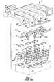
- the prior art manifold assembly comprises single fuel rail or conduit 34, upper manifold portion 10 and lower manifold portions 18A and 18B.
- Upper manifold portion 10 has ducts 14A, 14B, 14C and 14D.
- Lower manifold portions, 18A and 18B have ducts 26, to mount with ducts of upper manifold portion 10.
- duct 14A mounts with duct 26 to permit the communication of air from upper manifold portion 10 through lower manifold portion 18A to engine 24 (shown schematically).
- This assembly has seals 30 at the interface between upper manifold portion 10 and lower manifold portions, 18A and 18B.
- Fuel conduit 34 has fuel injectors such as fuel injector 38A, 38B, 38C and 38D. Due to the use of a single fuel conduit 34, fuel injector 38C extends from fuel conduit 34 in a direction transverse to the direction of extension of fuel injector 38D, thus forming an upside down v-shaped form. Each injector is inserted into a corresponding fuel injector port, such as fuel injector port 22, on each of the lower manifold portions, 18A and 18B.
- upper manifold portion 10 By locating injector ports 22 on the air induction manifold, upper manifold portion 10 must be separated from lower manifold portions 18A and 18B to permit installation of fuel conduit 34 and its subsequent service. Hence, lower manifold portions, 18A and 18B, are mounted on engine 24. Fuel conduit 34 and fuel-injectors, such as 38D, are installed into respective fuel injector ports, such as fuel injector port 22. Seals 30 are installed as known between upper manifold portion 10 and lower manifold portions, 18A and 18B. Seals 31 are installed between lower manifold portions, 18A and 18B, and engine 24. Upper manifold portion 10 is then mounted to lower manifold portions 18A and 18B.
- FIG 1A shows another view of the manifold assembly of Figure 1.
- Duct 14D and duct 14C mount to lower manifold portions 18B and 18A, respectively, and communicate air to engine 24 through duct passages 25 and 26.
- Duct upper faces 23 and 27 act as interfaces between ducts 14D and 14C and duct passages 25 and 26.
- duct 14D mounts to duct mount 23 of lower manifold portion 18B, permitting air to pass through duct passage 25 to engine 24.
- Both ducts mounts 23 and 27 have a height H2.
- Fuel rail 34 has fuel injectors 54D and 54C, which are disposed in fuel injector passages, 55D and 55C, respectively.
- Fuel ports mounts 22 and 29, like other port mounts of the assembly, have a minimum height H1 to meet fuel injector 54D and 54C. As shown, height H1 of fuel injector port 22, is less than height H2 of duct upper face 23. Also, fuel injector passage 55C has a length L1 less than the length L2 of duct passage 26.
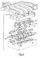
- FIG. 2 illustrates an embodiment of the invention, including air intake manifold 42, fuel conduit 46, and support members, 50A and 50B.
- air intake manifold 42 comprises a single unit communicating air to a vehicle engine through ducts such as 70A, 70B, 70C and 70D.
- Fuel rail 46 is mountable to air intake manifold 42, and has fuel injectors 54A, 54B, 54C, and 54D, which have a v-shaped form as shown with fuel injectors 54C and 54D.
- support member 50A and support member 50B may comprise a planar member.
- Each support member also has fuel injector port mounts, such as fuel injector port mounts 58A, 58B, 58C, and 58D that may comprise columns with passages to receive the fuel injector nozzles.
- fuel injector port mounts 58A, 58B, 58C, and 58D may comprise columns with passages to receive the fuel injector nozzles.
- support members 50A and 50B have duct mounts, such as 59D and 59C, with passages.
- support members, 50A and 50B each have fuel injector passages, such as 53D and 53C, which receive fuel injectors, 54D and 54C, respectively.
- fuel injector passages, 53D and 53C have a minimum length L3 greater than the length L4 of duct passages, 62D and 62C.
- fuel injector port mounts, such as fuel injector port mounts, 58D and 58C have a minimum height H3, which is greater than the height H4, to the upper face of duct mounts, 59D and 59C.
- the manifold assembly is then installed on an engine by mounting support member 50A and 50B to each respective bank of engine 52.
- Fuel conduit 46 is oriented to allow fuel injectors 54A, 54B, 54C and 54D to be received respectively by fuel injector port mounts 58A, 58B, 58C and 58D.
- Fuel rail 46 is then mounted as known to air intake manifold 42.
- Air intake manifold 42 is mounted to engine 52 through support members 50A and 50B.
- duct 70D interfaces with duct mount 59D while duct 70C interfaces with duct mount 59C.
- the ducts may be mounted as known. Accordingly, the invention avoids the use of additional components found in the prior art.
- air intake manifold 42 may be constructed using a single tool rather than multiple tools. Assembly and handling of these components is thereby simplified.
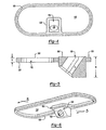
- Figure 3 illustrates an underside view of support members 50A and 50B of Figure 1. Shown from this view are duct passages 62A, 62B, 62C, 62D, 62E and 62F to permit communication of air from ducts, such as duct 70A, 70B, 70C and 70D, as shown in Figure 2 to vehicle engine 52. Seals, such as seal 74, may be provided around each duct passage to assist in the flow of air to engine 52. Also, as shown in Figure 2, seals, such as seals 59D and 59C, may be employed between support members, 50A and 50B, and ducts, 70D and 70C.
- FIG. 4 shows a plan view of this embodiment comprising injector port mount 104 and seal 100.
- Seal 100 may be an elastomer seal molded as known with injector port mount 104 to provide a sealing surface between say duct 70D and vehicle engine 52.
- Injector port mount 104 has injector port passage 108 to receive a fuel injector and assist in the communication of fuel to vehicle engine 52.
- Injector port mount 104 may be supported as known.
- An injector port mount and seal would be provided for each individual duct, providing a cheaper way to interface the fuel injectors and manifold ducts with the vehicle engine.
- Figure 5 illustrates a cross-sectional view of the embodiment of Figure 4.
- Figure 5 shows that the length (also height) K of duct passage 110 is less than the length J of fuel injector port passage 108.
- the height, K, of seal 100 is also less than the height, M, of fuel injector port mount 104.
- Figure 5 also highlights seal 100 extending around injector port mount 104. This sealing of injector port mount 104 is also shown in Figure 6. This seal ensures sufficient communication of air from duct to vehicle engine. Seals may thus be of carrier gasket or individual port design. It is simply desirable that the port be part of the seal and not the manifold.
- the v-bank engine may comprise a central v-bank, external v-bank, or other v-bank engine. Additionally, the invention may be employed with a single line engine as well.
- a molded composite manifold which may be produced by shell, lost core or hybrid construction. Details surrounding the manufacture of these manifolds are well known.
- the invention may also be employed for a metal manifold.
Description
- This invention relates to an air intake manifold assembly for a v-shaped engine having two banks forming a V pattern.
- For such an engine, manufacturers employ air intake manifold assemblies that comprise an upper manifold portion and two lower manifold portions. A single fuel rail or conduit is frequently used to communicate fuel from a fuel tank to the combustion chambers of both banks of the engine through fuel injectors of the fuel rail. The fuel injectors that extend from the fuel rail also take a v-shaped form to meet each cylinder. Due to the proximity of the ducts of the air intake manifolds to the ports for the fuel injectors, manufacturers mold the ports and ducts together as part of the lower portion of the manifold assembly.
- The manifold assembly generally consists of a pair of lower manifold portions, a fuel rail assembly, and a single upper manifold portion. The fuel rail is installed into the lower manifold portions from above. Then, the upper intake manifold is installed on top. A set of seals and additional components hold the manifold portions together. Moreover, the interface between the lower intake manifold and the engine requires another set of seals and components to assemble the lower intake manifolds to the engine.
- The present design of manifold assembly has several drawbacks. The splitting of the manifold assembly into upper and lower manifold portions requires additional componentry as well as labor and time to assemble. Each portion also requires separate tooling and capital expenditures to manufacture. Finally, handling and inventory costs are increased as a consequence of the multiple components required by the current design.
- A need therefore exists for a simplified manifold design that permits easy installation and service of the fuel rail and manifold assembly for a v-bank engine.
- US patent no. 4,932,360 describes a suction arrangement for an internal combustion engine.
- The present invention moves the location of the fuel injector ports from the air intake manifold to a separate support. In so doing, the lower portions of the air intake manifold assembly may be combined with the upper portion to form a single unit, thereby reducing the number of manifold components. As a consequence, no additional tooling is required to form the lower portions of the air intake manifold. Only a single tool to form the single unit manifold is needed. Labor and parts costs are also reduced.
- The invention comprises a manifold assembly. The air intake manifold has ducts that communicate air to the engine. A single fuel rail has fuel injectors for supplying the engine with fuel. The inventive design employs a separate support having ports to receive the fuel injectors and having seals to assist in the communication of air from the air intake manifold to the engine.
- The support member has duct passages in communication with the ducts of the manifold and has fuel injector port passages in communication with the fuel injectors of the fuel rail. In contrast to the prior art, the fuel injector port passages may have a predetermined length greater than the length of the duct passages. The support member may comprise a planar member. For a v-shaped engine, two support members may be used to interface the ducts and injectors of the manifold and fuel rail with each bank of the engine.
- The fuel conduit may be mounted to the air intake manifold. Seals may be used between the duct passages and the ducts. These seals may be mounted to the support member. In addition, seals may be used between the duct passage and the engine. These seals may be mounted to the support member.
- The air intake manifold assembly may have a planar member acting as a support comprising duct mounts in communication with the ducts of the manifold and fuel injector port mounts in communication the fuel injectors of the fuel rail. The fuel injector port mounts may have a predetermined thickness greater than the thickness of the duct mounts. Seals may be used between the duct mount and the duct and may be mounted to the planar member. Seals may also be employed between the duct mounts and the engine and mounted to the planar member.
- Hence, the fuel injector ports are located separately from the air intake manifold. The support member is then mounted to the engine with each fuel injector positioned into each fuel injector port. This design then allows the air intake manifold to be mounted as a single unit on the engine.
- The various features and advantages of this invention will become apparent to those skilled in the art from the following detailed description of the currently preferred embodiment. The drawings that accompany the detailed description can be briefly described as follows.
- Figure 1 shows a prior art manifold assembly employing an upper manifold portion and two lower manifold portions of an air intake manifold.
- Figure 1A shows another view of the prior art manifold assembly of Figure 1.
- Figure 2 illustrates an embodiment of the invention, including an air intake manifold, fuel conduit, and the support member with fuel injector ports passages and duct passages.
- Figure 2A shows another view of the embodiment of Figure 2, highlighting the fuel injector port passages, fuel injector port mounts, and duct passages and duct mounts.
- Figure 3 illustrates the support member of Figure 2.
- Figure 4 illustrates a plan view of another embodiment of the invention.
- Figure 5 illustrates a cross-sectional view of the embodiment of Figure 4.
- Figure 6 illustrates a perspective view of the embodiment of Figure 4.
- As shown in Figure 1, for a v-bank engine, the prior art manifold assembly comprises single fuel rail or
conduit 34,upper manifold portion 10 andlower manifold portions Upper manifold portion 10 hasducts ducts 26, to mount with ducts ofupper manifold portion 10. Here,duct 14A mounts withduct 26 to permit the communication of air fromupper manifold portion 10 throughlower manifold portion 18A to engine 24 (shown schematically). This assembly hasseals 30 at the interface betweenupper manifold portion 10 and lower manifold portions, 18A and 18B. - On lower manifold portions, 18A and 18B, fuel injector ports, such as
fuel injector port 22, are located, thus combining the fuel injector ports with lower manifold portions, 18A and 18B.Fuel conduit 34 has fuel injectors such asfuel injector single fuel conduit 34,fuel injector 38C extends fromfuel conduit 34 in a direction transverse to the direction of extension offuel injector 38D, thus forming an upside down v-shaped form. Each injector is inserted into a corresponding fuel injector port, such asfuel injector port 22, on each of the lower manifold portions, 18A and 18B. By locatinginjector ports 22 on the air induction manifold,upper manifold portion 10 must be separated fromlower manifold portions fuel conduit 34 and its subsequent service. Hence, lower manifold portions, 18A and 18B, are mounted onengine 24.Fuel conduit 34 and fuel-injectors, such as 38D, are installed into respective fuel injector ports, such asfuel injector port 22.Seals 30 are installed as known between uppermanifold portion 10 and lower manifold portions, 18A and 18B.Seals 31 are installed between lower manifold portions, 18A and 18B, andengine 24.Upper manifold portion 10 is then mounted to lowermanifold portions - Figure 1A shows another view of the manifold assembly of Figure 1.
Duct 14D andduct 14C mount to lowermanifold portions engine 24 throughduct passages ducts duct passages duct 14D mounts toduct mount 23 of lowermanifold portion 18B, permitting air to pass throughduct passage 25 toengine 24. Both ducts mounts 23 and 27 have a height H2. -
Fuel rail 34 hasfuel injectors fuel injector fuel injector port 22, is less than height H2 of ductupper face 23. Also,fuel injector passage 55C has a length L1 less than the length L2 ofduct passage 26. - Figure 2 illustrates an embodiment of the invention, including
air intake manifold 42,fuel conduit 46, and support members, 50A and 50B. As shown,air intake manifold 42 comprises a single unit communicating air to a vehicle engine through ducts such as 70A, 70B, 70C and 70D.Fuel rail 46 is mountable toair intake manifold 42, and hasfuel injectors fuel injectors - In contrast to the prior art,
support member 50A andsupport member 50B may comprise a planar member. Each support member also has fuel injector port mounts, such as fuel injector port mounts 58A, 58B, 58C, and 58D that may comprise columns with passages to receive the fuel injector nozzles. Also,support members - As shown in Figure 2A, support members, 50A and 50B, each have fuel injector passages, such as 53D and 53C, which receive fuel injectors, 54D and 54C, respectively. Unlike the prior art, however, fuel injector passages, 53D and 53C, have a minimum length L3 greater than the length L4 of duct passages, 62D and 62C. Moreover, fuel injector port mounts, such as fuel injector port mounts, 58D and 58C, have a minimum height H3, which is greater than the height H4, to the upper face of duct mounts, 59D and 59C.
- Location of the ports on a support member separate from
air intake manifold 42 permits the employment of a single unit manifold body while still permitting easy installation and subsequent service offuel conduit 46. The manifold assembly is then installed on an engine by mountingsupport member engine 52.Fuel conduit 46 is oriented to allowfuel injectors Fuel rail 46 is then mounted as known toair intake manifold 42.Air intake manifold 42 is mounted toengine 52 throughsupport members duct 70D interfaces withduct mount 59D whileduct 70C interfaces withduct mount 59C. The ducts may be mounted as known. Accordingly, the invention avoids the use of additional components found in the prior art. Moreover,air intake manifold 42 may be constructed using a single tool rather than multiple tools. Assembly and handling of these components is thereby simplified. - Figure 3 illustrates an underside view of
support members duct passages duct vehicle engine 52. Seals, such asseal 74, may be provided around each duct passage to assist in the flow of air toengine 52. Also, as shown in Figure 2, seals, such asseals - An alternative concept to the support member would be to overmold the injector ports with elastomer. Rather than have a planar support member for duct seals and fuel injector port mounts, duct seals and fuel injector port mounts may be individually employed. Figures 4, 5 and 6 illustrate such an embodiment. Figure 4 shows a plan view of this embodiment comprising
injector port mount 104 andseal 100.Seal 100 may be an elastomer seal molded as known withinjector port mount 104 to provide a sealing surface betweensay duct 70D andvehicle engine 52.Injector port mount 104 hasinjector port passage 108 to receive a fuel injector and assist in the communication of fuel tovehicle engine 52.Injector port mount 104 may be supported as known. An injector port mount and seal would be provided for each individual duct, providing a cheaper way to interface the fuel injectors and manifold ducts with the vehicle engine. - Figure 5 illustrates a cross-sectional view of the embodiment of Figure 4. In particular, Figure 5 shows that the length (also height) K of
duct passage 110 is less than the length J of fuelinjector port passage 108. The height, K, ofseal 100 is also less than the height, M, of fuelinjector port mount 104. Figure 5 also highlightsseal 100 extending aroundinjector port mount 104. This sealing ofinjector port mount 104 is also shown in Figure 6. This seal ensures sufficient communication of air from duct to vehicle engine. Seals may thus be of carrier gasket or individual port design. It is simply desirable that the port be part of the seal and not the manifold. - This disclosure shows the invention employed with a v-bank engine. The v-bank engine may comprise a central v-bank, external v-bank, or other v-bank engine. Additionally, the invention may be employed with a single line engine as well.
- Finally, the concept is depicted for a molded composite manifold, which may be produced by shell, lost core or hybrid construction. Details surrounding the manufacture of these manifolds are well known. The invention may also be employed for a metal manifold.
Claims (8)
- A manifold assembly comprising:an air intake manifold (42) having at least one duct (70A-D) communicating air to an engine (52);a fuel conduit (46) having at least one fuel injector (54A-D) for communicating fuel to Said engine wherein said fuel conduit comprises at least a first fuel injector (54C) and a second fuel injector (54D) extending from said fuel conduit (46) wherein said first fuel injector (54C) extends in a direction transverse to said second fuel injector (54D); andat least one support member (50A, B) comprising at least one duct passage (62A-D) in communication with said at least one duct (70A-D) and at least one fuel injector port passage (53C, 53D) in communication with said at least one fuel injector (54C, 54D) characterised in that said fuel injector port passage (53C) has a predetermined length (L3) greater than the length (L4) of said duct passage (62C) said support member (50A).
- The manifold assembly of Claim wherein said support member (50A,B) comprises a fuel injector port mount (58A-D) encompassing said fuel injector port passage and a seal (100) encompassing said duct passage operatively connected to said fuel injector port mount.
- The manifold assembly of Claim 1 wherein said support member (50A,B) comprises a generally planar member.
- The manifold assembly of Claim 1 wherein said fuel conduit (46) is mounted to said air intake manifold (42).
- The manifold assembly of Claim 1 wherein said at least one support member (50A,B) comprises a first support member (50A) and a second support member (50B) wherein said first support member (50A) comprises at least one fuel injector port passage (53C) in communication with said first fuel injector (54C) and said second support member (50B) comprises at least one fuel injector port passage (53D) communication with said second fuel injector (54D).
- The manifold assembly of Claim 1 including a seal (100) between said duct passage and said duct.
- The manifold assembly of Claim 6 wherein said seal (100) is mounted to said support member.
- The manifold assembly of Claim 1 including a seal (74) between said duct passage and said engine.
Applications Claiming Priority (2)
| Application Number | Priority Date | Filing Date | Title |
|---|---|---|---|
| US25963701P | 2001-01-04 | 2001-01-04 | |
| US259637P | 2001-01-04 |
Publications (3)
| Publication Number | Publication Date |
|---|---|
| EP1221548A2 EP1221548A2 (en) | 2002-07-10 |
| EP1221548A3 EP1221548A3 (en) | 2003-11-05 |
| EP1221548B1 true EP1221548B1 (en) | 2006-03-01 |
Family
ID=22985737
Family Applications (1)
| Application Number | Title | Priority Date | Filing Date |
|---|---|---|---|
| EP01205018A Expired - Lifetime EP1221548B1 (en) | 2001-01-04 | 2001-12-20 | Monocoque intake manifold assembly |
Country Status (3)
| Country | Link |
|---|---|
| US (1) | US6575141B2 (en) |
| EP (1) | EP1221548B1 (en) |
| DE (1) | DE60117460T2 (en) |
Families Citing this family (11)
| Publication number | Priority date | Publication date | Assignee | Title |
|---|---|---|---|---|
| US7191748B2 (en) * | 2003-02-13 | 2007-03-20 | Siemens Canada Limited | Integrated air and fuel carrier module |
| US7007674B2 (en) * | 2003-04-01 | 2006-03-07 | Robert Bosch Corporation | Fuel rail assembly |
| US20050045155A1 (en) * | 2003-08-28 | 2005-03-03 | Harvey Bruce J. | Intake manifold with injectors and captive fuel rail |
| US6840221B1 (en) * | 2003-12-23 | 2005-01-11 | International Engine Intellectual Property Company, Llc | Runnerless engine intake manifold having integral fuel delivery groove or bore |
| US7028668B1 (en) | 2004-12-21 | 2006-04-18 | Robert Bosch Gmbh | Self-damping fuel rail |
| DE102005009117A1 (en) * | 2005-03-01 | 2006-09-07 | Dr.Ing.H.C. F. Porsche Ag | Internal combustion engine with at least two rows of cylinder banks |
| GB0522982D0 (en) * | 2005-11-10 | 2005-12-21 | Kennedy Roger | Induction regulator block |
| FR2950396B1 (en) * | 2009-09-22 | 2012-04-27 | Mark Iv Systemes Moteurs Sa | FUNCTIONAL MODULE INTEGRATING A DISTRIBUTOR AND INJECTION RAMP AND METHOD FOR MANUFACTURING THE SAME |
| FR2958338B1 (en) * | 2010-03-31 | 2012-03-23 | Mark Iv Systemes Moteurs Sa | INTAKE DISTRIBUTION DEVICE INCORPORATING PLATINUM AND METHOD OF MOUNTING IT TO A MOTOR |
| USD765142S1 (en) * | 2014-08-08 | 2016-08-30 | Kenneth J. Hunter | Combustion engine intake manifold for snowmobiles and all terrain vehicles |
| USD766331S1 (en) * | 2015-01-29 | 2016-09-13 | Vaztec, Llc | Seal |
Family Cites Families (12)
| Publication number | Priority date | Publication date | Assignee | Title |
|---|---|---|---|---|
| JPS60187759A (en) * | 1984-03-06 | 1985-09-25 | Mazda Motor Corp | Intake apparatus for engine |
| US4932368A (en) * | 1988-01-28 | 1990-06-12 | Mazda Motor Corporation | Suction arrangement for internal combustion engine |
| US5022371A (en) * | 1989-09-29 | 1991-06-11 | Siemens-Bendix Automotive Electronics L.P. | Molded plastic fuel rail for an internal combustion engine |
| US5163406A (en) * | 1990-08-07 | 1992-11-17 | Siemens Automotive L.P. | Intake manifold/fuel rail |
| FR2697293B1 (en) * | 1992-10-26 | 1994-11-10 | Solex | Feeding device with integrated tubing. |
| US5515822A (en) * | 1994-05-19 | 1996-05-14 | Yamaha Hatsudoki Kabushiki Kaisha | Intake system |
| US5657733A (en) | 1996-01-22 | 1997-08-19 | Siemens Electroic Limited | Fuel injector mounting for molded intake manifold with integrated fuel rail |
| JP2864365B2 (en) * | 1996-04-16 | 1999-03-03 | 本田技研工業株式会社 | Engine intake system |
| US6520154B2 (en) * | 1998-02-20 | 2003-02-18 | Delphi Technologies, Inc. | Side feed fuel injector and integrated fuel rail/intake manifold |
| US6192849B1 (en) * | 1999-06-18 | 2001-02-27 | Siemens Canada Limited | Manifold housing system |
| US6089199A (en) * | 1999-03-01 | 2000-07-18 | Ford Global Technologies, Inc. | Air cleaner module having integrated engine valve cover |
| US6308686B1 (en) * | 1999-11-18 | 2001-10-30 | Siemens Canada Limited | Intake manifold with internal fuel rail and injectors |
-
2001
- 2001-12-20 DE DE60117460T patent/DE60117460T2/en not_active Expired - Lifetime
- 2001-12-20 EP EP01205018A patent/EP1221548B1/en not_active Expired - Lifetime
- 2001-12-20 US US10/029,047 patent/US6575141B2/en not_active Expired - Lifetime
Also Published As
| Publication number | Publication date |
|---|---|
| US6575141B2 (en) | 2003-06-10 |
| US20020083924A1 (en) | 2002-07-04 |
| EP1221548A2 (en) | 2002-07-10 |
| DE60117460D1 (en) | 2006-04-27 |
| EP1221548A3 (en) | 2003-11-05 |
| DE60117460T2 (en) | 2006-08-24 |
Similar Documents
| Publication | Publication Date | Title |
|---|---|---|
| EP1221548B1 (en) | Monocoque intake manifold assembly | |
| US5465699A (en) | Intake pipe arrangement for an internal combustion engine having individual arc-shaped cylinder intake pipes | |
| CN100460658C (en) | Cylinder head cover | |
| US5657733A (en) | Fuel injector mounting for molded intake manifold with integrated fuel rail | |
| EP2599989B1 (en) | Air-intake device | |
| US20060042601A1 (en) | Fuel routing structure for a V-type engine | |
| EP1452720B1 (en) | Engine air intake manifold | |
| EP2133521A2 (en) | Blow-by gas recirculation structure for internal combustion engine | |
| US5887565A (en) | Lubricating oil passage structure for engine | |
| EP1024280B1 (en) | Intake manifold | |
| EP0603924B1 (en) | Cylinder head for internal combustion engine | |
| WO1993001408A1 (en) | Arrangement for a fuel line in an internal combustion engine | |
| EP0245009B1 (en) | A fuel rail | |
| US6129133A (en) | Method for forming a cylinder bore isolator core for casting engine cylinder blocks | |
| EP1375897B1 (en) | Vehicle non-metallic intake manifold having an integrated metallic fuel rail | |
| EP0365529B1 (en) | Fuel injection system component | |
| EP3379064B1 (en) | Cylinder head of internal combustion engine | |
| JP2003035228A (en) | Intake device of engine | |
| US7900442B2 (en) | Engine including secondary air supply apparatus | |
| JPS6228038B2 (en) | ||
| US6009855A (en) | Fuel injection system for a multicylinder internal combustion engine with a fuel supply line serving as high pressure storage device | |
| JPH0237104A (en) | Blow-by gas processor of engine | |
| JP2007009829A (en) | Vehicle | |
| JPH07208298A (en) | Fuel distributing pipe for internal combustion engine | |
| CN109723585B (en) | Assembly structure for intake manifold |
Legal Events
| Date | Code | Title | Description |
|---|---|---|---|
| PUAI | Public reference made under article 153(3) epc to a published international application that has entered the european phase |
Free format text: ORIGINAL CODE: 0009012 |
|
| AK | Designated contracting states |
Kind code of ref document: A2 Designated state(s): AT BE CH CY DE DK ES FI FR GB GR IE IT LI LU MC NL PT SE TR |
|
| AX | Request for extension of the european patent |
Free format text: AL;LT;LV;MK;RO;SI |
|
| RAP1 | Party data changed (applicant data changed or rights of an application transferred) |
Owner name: SIEMENS VDO AUTOMOTIVE INC. |
|
| PUAL | Search report despatched |
Free format text: ORIGINAL CODE: 0009013 |
|
| AK | Designated contracting states |
Kind code of ref document: A3 Designated state(s): AT BE CH CY DE DK ES FI FR GB GR IE IT LI LU MC NL PT SE TR |
|
| AX | Request for extension of the european patent |
Extension state: AL LT LV MK RO SI |
|
| RIC1 | Information provided on ipc code assigned before grant |
Ipc: 7F 02M 69/46 B Ipc: 7F 02M 35/116 A Ipc: 7F 02B 75/22 B Ipc: 7F 02M 35/10 B |
|
| 17P | Request for examination filed |
Effective date: 20040421 |
|
| 17Q | First examination report despatched |
Effective date: 20040608 |
|
| AKX | Designation fees paid |
Designated state(s): DE FR GB |
|
| GRAP | Despatch of communication of intention to grant a patent |
Free format text: ORIGINAL CODE: EPIDOSNIGR1 |
|
| GRAS | Grant fee paid |
Free format text: ORIGINAL CODE: EPIDOSNIGR3 |
|
| GRAA | (expected) grant |
Free format text: ORIGINAL CODE: 0009210 |
|
| AK | Designated contracting states |
Kind code of ref document: B1 Designated state(s): DE FR GB |
|
| REG | Reference to a national code |
Ref country code: GB Ref legal event code: FG4D |
|
| REF | Corresponds to: |
Ref document number: 60117460 Country of ref document: DE Date of ref document: 20060427 Kind code of ref document: P |
|
| PLBE | No opposition filed within time limit |
Free format text: ORIGINAL CODE: 0009261 |
|
| STAA | Information on the status of an ep patent application or granted ep patent |
Free format text: STATUS: NO OPPOSITION FILED WITHIN TIME LIMIT |
|
| 26N | No opposition filed |
Effective date: 20061204 |
|
| EN | Fr: translation not filed | ||
| PG25 | Lapsed in a contracting state [announced via postgrant information from national office to epo] |
Ref country code: FR Free format text: LAPSE BECAUSE OF FAILURE TO SUBMIT A TRANSLATION OF THE DESCRIPTION OR TO PAY THE FEE WITHIN THE PRESCRIBED TIME-LIMIT Effective date: 20070309 |
|
| PG25 | Lapsed in a contracting state [announced via postgrant information from national office to epo] |
Ref country code: FR Free format text: LAPSE BECAUSE OF FAILURE TO SUBMIT A TRANSLATION OF THE DESCRIPTION OR TO PAY THE FEE WITHIN THE PRESCRIBED TIME-LIMIT Effective date: 20060301 |
|
| PGFP | Annual fee paid to national office [announced via postgrant information from national office to epo] |
Ref country code: GB Payment date: 20151230 Year of fee payment: 15 |
|
| PGFP | Annual fee paid to national office [announced via postgrant information from national office to epo] |
Ref country code: DE Payment date: 20160302 Year of fee payment: 15 |
|
| REG | Reference to a national code |
Ref country code: DE Ref legal event code: R119 Ref document number: 60117460 Country of ref document: DE |
|
| GBPC | Gb: european patent ceased through non-payment of renewal fee |
Effective date: 20161220 |
|
| PG25 | Lapsed in a contracting state [announced via postgrant information from national office to epo] |
Ref country code: DE Free format text: LAPSE BECAUSE OF NON-PAYMENT OF DUE FEES Effective date: 20170701 Ref country code: GB Free format text: LAPSE BECAUSE OF NON-PAYMENT OF DUE FEES Effective date: 20161220 |