EP1221548A2 - Monocoque intake manifold assembly - Google Patents
Monocoque intake manifold assembly Download PDFInfo
- Publication number
- EP1221548A2 EP1221548A2 EP01205018A EP01205018A EP1221548A2 EP 1221548 A2 EP1221548 A2 EP 1221548A2 EP 01205018 A EP01205018 A EP 01205018A EP 01205018 A EP01205018 A EP 01205018A EP 1221548 A2 EP1221548 A2 EP 1221548A2
- Authority
- EP
- European Patent Office
- Prior art keywords
- fuel injector
- fuel
- duct
- support member
- manifold
- Prior art date
- Legal status (The legal status is an assumption and is not a legal conclusion. Google has not performed a legal analysis and makes no representation as to the accuracy of the status listed.)
- Granted
Links
Images


Classifications
-
- F—MECHANICAL ENGINEERING; LIGHTING; HEATING; WEAPONS; BLASTING
- F02—COMBUSTION ENGINES; HOT-GAS OR COMBUSTION-PRODUCT ENGINE PLANTS
- F02M—SUPPLYING COMBUSTION ENGINES IN GENERAL WITH COMBUSTIBLE MIXTURES OR CONSTITUENTS THEREOF
- F02M35/00—Combustion-air cleaners, air intakes, intake silencers, or induction systems specially adapted for, or arranged on, internal-combustion engines
- F02M35/10—Air intakes; Induction systems
- F02M35/10209—Fluid connections to the air intake system; their arrangement of pipes, valves or the like
- F02M35/10216—Fuel injectors; Fuel pipes or rails; Fuel pumps or pressure regulators
-
- F—MECHANICAL ENGINEERING; LIGHTING; HEATING; WEAPONS; BLASTING
- F02—COMBUSTION ENGINES; HOT-GAS OR COMBUSTION-PRODUCT ENGINE PLANTS
- F02B—INTERNAL-COMBUSTION PISTON ENGINES; COMBUSTION ENGINES IN GENERAL
- F02B75/00—Other engines
- F02B75/16—Engines characterised by number of cylinders, e.g. single-cylinder engines
- F02B75/18—Multi-cylinder engines
- F02B75/22—Multi-cylinder engines with cylinders in V, fan, or star arrangement
-
- F—MECHANICAL ENGINEERING; LIGHTING; HEATING; WEAPONS; BLASTING
- F02—COMBUSTION ENGINES; HOT-GAS OR COMBUSTION-PRODUCT ENGINE PLANTS
- F02M—SUPPLYING COMBUSTION ENGINES IN GENERAL WITH COMBUSTIBLE MIXTURES OR CONSTITUENTS THEREOF
- F02M35/00—Combustion-air cleaners, air intakes, intake silencers, or induction systems specially adapted for, or arranged on, internal-combustion engines
- F02M35/10—Air intakes; Induction systems
- F02M35/10006—Air intakes; Induction systems characterised by the position of elements of the air intake system in direction of the air intake flow, i.e. between ambient air inlet and supply to the combustion chamber
- F02M35/10078—Connections of intake systems to the engine
- F02M35/10085—Connections of intake systems to the engine having a connecting piece, e.g. a flange, between the engine and the air intake being foreseen with a throttle valve, fuel injector, mixture ducts or the like
-
- F—MECHANICAL ENGINEERING; LIGHTING; HEATING; WEAPONS; BLASTING
- F02—COMBUSTION ENGINES; HOT-GAS OR COMBUSTION-PRODUCT ENGINE PLANTS
- F02M—SUPPLYING COMBUSTION ENGINES IN GENERAL WITH COMBUSTIBLE MIXTURES OR CONSTITUENTS THEREOF
- F02M35/00—Combustion-air cleaners, air intakes, intake silencers, or induction systems specially adapted for, or arranged on, internal-combustion engines
- F02M35/10—Air intakes; Induction systems
- F02M35/10091—Air intakes; Induction systems characterised by details of intake ducts: shapes; connections; arrangements
- F02M35/10111—Substantially V-, C- or U-shaped ducts in direction of the flow path
-
- F—MECHANICAL ENGINEERING; LIGHTING; HEATING; WEAPONS; BLASTING
- F02—COMBUSTION ENGINES; HOT-GAS OR COMBUSTION-PRODUCT ENGINE PLANTS
- F02M—SUPPLYING COMBUSTION ENGINES IN GENERAL WITH COMBUSTIBLE MIXTURES OR CONSTITUENTS THEREOF
- F02M35/00—Combustion-air cleaners, air intakes, intake silencers, or induction systems specially adapted for, or arranged on, internal-combustion engines
- F02M35/10—Air intakes; Induction systems
- F02M35/10242—Devices or means connected to or integrated into air intakes; Air intakes combined with other engine or vehicle parts
- F02M35/10288—Air intakes combined with another engine part, e.g. cylinder head cover or being cast in one piece with the exhaust manifold, cylinder head or engine block
-
- F—MECHANICAL ENGINEERING; LIGHTING; HEATING; WEAPONS; BLASTING
- F02—COMBUSTION ENGINES; HOT-GAS OR COMBUSTION-PRODUCT ENGINE PLANTS
- F02M—SUPPLYING COMBUSTION ENGINES IN GENERAL WITH COMBUSTIBLE MIXTURES OR CONSTITUENTS THEREOF
- F02M35/00—Combustion-air cleaners, air intakes, intake silencers, or induction systems specially adapted for, or arranged on, internal-combustion engines
- F02M35/10—Air intakes; Induction systems
- F02M35/10314—Materials for intake systems
- F02M35/10321—Plastics; Composites; Rubbers
-
- F—MECHANICAL ENGINEERING; LIGHTING; HEATING; WEAPONS; BLASTING
- F02—COMBUSTION ENGINES; HOT-GAS OR COMBUSTION-PRODUCT ENGINE PLANTS
- F02M—SUPPLYING COMBUSTION ENGINES IN GENERAL WITH COMBUSTIBLE MIXTURES OR CONSTITUENTS THEREOF
- F02M35/00—Combustion-air cleaners, air intakes, intake silencers, or induction systems specially adapted for, or arranged on, internal-combustion engines
- F02M35/10—Air intakes; Induction systems
- F02M35/1034—Manufacturing and assembling intake systems
- F02M35/10347—Moulding, casting or the like
-
- F—MECHANICAL ENGINEERING; LIGHTING; HEATING; WEAPONS; BLASTING
- F02—COMBUSTION ENGINES; HOT-GAS OR COMBUSTION-PRODUCT ENGINE PLANTS
- F02M—SUPPLYING COMBUSTION ENGINES IN GENERAL WITH COMBUSTIBLE MIXTURES OR CONSTITUENTS THEREOF
- F02M35/00—Combustion-air cleaners, air intakes, intake silencers, or induction systems specially adapted for, or arranged on, internal-combustion engines
- F02M35/10—Air intakes; Induction systems
- F02M35/1034—Manufacturing and assembling intake systems
- F02M35/10354—Joining multiple sections together
-
- F—MECHANICAL ENGINEERING; LIGHTING; HEATING; WEAPONS; BLASTING
- F02—COMBUSTION ENGINES; HOT-GAS OR COMBUSTION-PRODUCT ENGINE PLANTS
- F02M—SUPPLYING COMBUSTION ENGINES IN GENERAL WITH COMBUSTIBLE MIXTURES OR CONSTITUENTS THEREOF
- F02M35/00—Combustion-air cleaners, air intakes, intake silencers, or induction systems specially adapted for, or arranged on, internal-combustion engines
- F02M35/10—Air intakes; Induction systems
- F02M35/104—Intake manifolds
- F02M35/116—Intake manifolds for engines with cylinders in V-arrangement or arranged oppositely relative to the main shaft
-
- F—MECHANICAL ENGINEERING; LIGHTING; HEATING; WEAPONS; BLASTING
- F02—COMBUSTION ENGINES; HOT-GAS OR COMBUSTION-PRODUCT ENGINE PLANTS
- F02M—SUPPLYING COMBUSTION ENGINES IN GENERAL WITH COMBUSTIBLE MIXTURES OR CONSTITUENTS THEREOF
- F02M69/00—Low-pressure fuel-injection apparatus ; Apparatus with both continuous and intermittent injection; Apparatus injecting different types of fuel
- F02M69/46—Details, component parts or accessories not provided for in, or of interest apart from, the apparatus covered by groups F02M69/02 - F02M69/44
- F02M69/462—Arrangement of fuel conduits, e.g. with valves for maintaining pressure in the pipes after the engine being shut-down
- F02M69/465—Arrangement of fuel conduits, e.g. with valves for maintaining pressure in the pipes after the engine being shut-down of fuel rails
-
- F—MECHANICAL ENGINEERING; LIGHTING; HEATING; WEAPONS; BLASTING
- F02—COMBUSTION ENGINES; HOT-GAS OR COMBUSTION-PRODUCT ENGINE PLANTS
- F02M—SUPPLYING COMBUSTION ENGINES IN GENERAL WITH COMBUSTIBLE MIXTURES OR CONSTITUENTS THEREOF
- F02M35/00—Combustion-air cleaners, air intakes, intake silencers, or induction systems specially adapted for, or arranged on, internal-combustion engines
- F02M35/10—Air intakes; Induction systems
- F02M35/10314—Materials for intake systems
- F02M35/10327—Metals; Alloys
Definitions
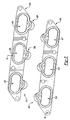
- Figure 3 illustrates the support member of Figure 2.
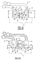
- Figure 5 illustrates a cross-sectional view of the embodiment of Figure 4.
Landscapes
- Engineering & Computer Science (AREA)
- Chemical & Material Sciences (AREA)
- Combustion & Propulsion (AREA)
- Mechanical Engineering (AREA)
- General Engineering & Computer Science (AREA)
- Manufacturing & Machinery (AREA)
- Fuel-Injection Apparatus (AREA)
Abstract
Description
Claims (15)
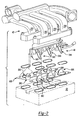
- A manifold assembly comprising:an air intake manifold having at least one duct communicating air to an engine;a fuel conduit having at least one fuel injector for communicating fuel to said engine wherein said fuel conduit comprises at least a first fuel injector and a second fuel injector extending from said fuel conduit wherein said first fuel injector extends in a direction transverse to said second fuel injector; andat least one support member comprising at least one duct passage in communication with said at least one duct and at least one fuel injector port passage in communication with said at least one fuel injector wherein said fuel injector port passage has a predetermined length greater than the length of said duct passage in said support member.
- The manifold assembly of Claim 1 wherein said support member comprises a fuel injector port mount encompassing said fuel injector port passage and a seal encompassing said duct passage operatively connected to said fuel injector port mount.
- The manifold assembly of Claim 1 wherein said support member comprises a generally planar member.
- The manifold assembly of Claim 1 wherein said fuel conduit is mounted to said air intake manifold.
- The manifold assembly of Claim 1 wherein said at least one support member comprises a first support member and a second support member wherein said first support member comprises at least one fuel injector port passage in communication with said first fuel injector and said second support member comprises at least one fuel injector port passage in communication with said second fuel injector.
- The manifold assembly of Claim 1 including a seal between said duct passage and said duct.
- The manifold assembly of Claim 6 wherein said seal is mounted to said support member.
- The manifold assembly of Claim 1 including a seal between said duct passage and said engine.
- A manifold assembly comprising:an air intake manifold having at least one duct communicating air to an engine;a fuel conduit having at least one fuel injector for communicating fuel to said engine wherein said fuel conduit comprises at least a first fuel injector and a second fuel injector extending from said fuel conduit wherein said first fuel injector extends in a direction transverse to said second fuel injector; andat least one planar member comprising an upper face duct mount in communication with said at least one duct and at least one fuel injector port mount in communication with said at least one fuel injector wherein said fuel injector port mount has a predetermined thickness greater than the thickness of said planar member between said upper face and a lower face.
- The manifold assembly of Claim 9 wherein said fuel conduit is mounted to said air intake manifold.
- The manifold assembly of Claim 9 wherein said at least one support member comprises a first support member and a second support member wherein said first support member comprises at least one fuel injector port mount in communication with said first fuel injector and said second support member comprises at least one fuel injector port mount in communication with said second fuel injector.
- The manifold assembly of Claim 9 including a seal between said duct mount and said duct.
- The manifold assembly of Claim 12 wherein said seal is mounted to said planar member.
- The manifold assembly of Claim 9 including a seal between said duct mount and said engine.
- The manifold assembly of Claim 14 wherein said seal is mounted to said support member.
Applications Claiming Priority (2)
| Application Number | Priority Date | Filing Date | Title |
|---|---|---|---|
| US25963701P | 2001-01-04 | 2001-01-04 | |
| US259637P | 2001-01-04 |
Publications (3)
| Publication Number | Publication Date |
|---|---|
| EP1221548A2 true EP1221548A2 (en) | 2002-07-10 |
| EP1221548A3 EP1221548A3 (en) | 2003-11-05 |
| EP1221548B1 EP1221548B1 (en) | 2006-03-01 |
Family
ID=22985737
Family Applications (1)
| Application Number | Title | Priority Date | Filing Date |
|---|---|---|---|
| EP01205018A Expired - Lifetime EP1221548B1 (en) | 2001-01-04 | 2001-12-20 | Monocoque intake manifold assembly |
Country Status (3)
| Country | Link |
|---|---|
| US (1) | US6575141B2 (en) |
| EP (1) | EP1221548B1 (en) |
| DE (1) | DE60117460T2 (en) |
Families Citing this family (11)
| Publication number | Priority date | Publication date | Assignee | Title |
|---|---|---|---|---|
| US7191748B2 (en) * | 2003-02-13 | 2007-03-20 | Siemens Canada Limited | Integrated air and fuel carrier module |
| US7007674B2 (en) * | 2003-04-01 | 2006-03-07 | Robert Bosch Corporation | Fuel rail assembly |
| EP1510687A2 (en) * | 2003-08-28 | 2005-03-02 | Siemens VDO Automotive Corporation | Intake manifold with injectors and captive fuel rail |
| US6840221B1 (en) * | 2003-12-23 | 2005-01-11 | International Engine Intellectual Property Company, Llc | Runnerless engine intake manifold having integral fuel delivery groove or bore |
| US7028668B1 (en) | 2004-12-21 | 2006-04-18 | Robert Bosch Gmbh | Self-damping fuel rail |
| DE102005009117A1 (en) * | 2005-03-01 | 2006-09-07 | Dr.Ing.H.C. F. Porsche Ag | Internal combustion engine with at least two rows of cylinder banks |
| GB0522982D0 (en) * | 2005-11-10 | 2005-12-21 | Kennedy Roger | Induction regulator block |
| FR2950396B1 (en) * | 2009-09-22 | 2012-04-27 | Mark Iv Systemes Moteurs Sa | FUNCTIONAL MODULE INTEGRATING A DISTRIBUTOR AND INJECTION RAMP AND METHOD FOR MANUFACTURING THE SAME |
| FR2958338B1 (en) * | 2010-03-31 | 2012-03-23 | Mark Iv Systemes Moteurs Sa | INTAKE DISTRIBUTION DEVICE INCORPORATING PLATINUM AND METHOD OF MOUNTING IT TO A MOTOR |
| USD765142S1 (en) * | 2014-08-08 | 2016-08-30 | Kenneth J. Hunter | Combustion engine intake manifold for snowmobiles and all terrain vehicles |
| USD766331S1 (en) * | 2015-01-29 | 2016-09-13 | Vaztec, Llc | Seal |
Family Cites Families (12)
| Publication number | Priority date | Publication date | Assignee | Title |
|---|---|---|---|---|
| JPS60187759A (en) * | 1984-03-06 | 1985-09-25 | Mazda Motor Corp | Intake apparatus for engine |
| US4932368A (en) * | 1988-01-28 | 1990-06-12 | Mazda Motor Corporation | Suction arrangement for internal combustion engine |
| US5022371A (en) * | 1989-09-29 | 1991-06-11 | Siemens-Bendix Automotive Electronics L.P. | Molded plastic fuel rail for an internal combustion engine |
| US5163406A (en) * | 1990-08-07 | 1992-11-17 | Siemens Automotive L.P. | Intake manifold/fuel rail |
| FR2697293B1 (en) * | 1992-10-26 | 1994-11-10 | Solex | Feeding device with integrated tubing. |
| US5515822A (en) * | 1994-05-19 | 1996-05-14 | Yamaha Hatsudoki Kabushiki Kaisha | Intake system |
| US5657733A (en) | 1996-01-22 | 1997-08-19 | Siemens Electroic Limited | Fuel injector mounting for molded intake manifold with integrated fuel rail |
| JP2864365B2 (en) * | 1996-04-16 | 1999-03-03 | 本田技研工業株式会社 | Engine intake system |
| US6520154B2 (en) * | 1998-02-20 | 2003-02-18 | Delphi Technologies, Inc. | Side feed fuel injector and integrated fuel rail/intake manifold |
| US6192849B1 (en) * | 1999-06-18 | 2001-02-27 | Siemens Canada Limited | Manifold housing system |
| US6089199A (en) * | 1999-03-01 | 2000-07-18 | Ford Global Technologies, Inc. | Air cleaner module having integrated engine valve cover |
| US6308686B1 (en) * | 1999-11-18 | 2001-10-30 | Siemens Canada Limited | Intake manifold with internal fuel rail and injectors |
-
2001
- 2001-12-20 EP EP01205018A patent/EP1221548B1/en not_active Expired - Lifetime
- 2001-12-20 US US10/029,047 patent/US6575141B2/en not_active Expired - Lifetime
- 2001-12-20 DE DE60117460T patent/DE60117460T2/en not_active Expired - Lifetime
Also Published As
| Publication number | Publication date |
|---|---|
| US20020083924A1 (en) | 2002-07-04 |
| DE60117460T2 (en) | 2006-08-24 |
| EP1221548B1 (en) | 2006-03-01 |
| DE60117460D1 (en) | 2006-04-27 |
| US6575141B2 (en) | 2003-06-10 |
| EP1221548A3 (en) | 2003-11-05 |
Similar Documents
| Publication | Publication Date | Title |
|---|---|---|
| EP1221548B1 (en) | Monocoque intake manifold assembly | |
| EP2599989B1 (en) | Air-intake device | |
| US7219657B2 (en) | Fuel routing structure for a V-type engine | |
| CN103775233B (en) | The jacket structure for water of cylinder head | |
| JPH0622140Y2 (en) | Fuel delivery pipe | |
| EP1452720B1 (en) | Engine air intake manifold | |
| EP2133521A2 (en) | Blow-by gas recirculation structure for internal combustion engine | |
| EP1024280B1 (en) | Intake manifold | |
| US5887565A (en) | Lubricating oil passage structure for engine | |
| US20020038653A1 (en) | Fuel supply system for vehicle | |
| US6644279B1 (en) | High pressure reservoir for fuel | |
| EP0603924B1 (en) | Cylinder head for internal combustion engine | |
| JP5938305B2 (en) | High pressure fuel delivery pipe for direct injection engines | |
| EP1375897B1 (en) | Vehicle non-metallic intake manifold having an integrated metallic fuel rail | |
| US6659058B2 (en) | Intake system of a V-type engine | |
| US7900442B2 (en) | Engine including secondary air supply apparatus | |
| US6009855A (en) | Fuel injection system for a multicylinder internal combustion engine with a fuel supply line serving as high pressure storage device | |
| JP3553783B2 (en) | Intake manifold | |
| JPH0237104A (en) | Blow-by gas processor of engine | |
| JPS6228038B2 (en) | ||
| US6994065B2 (en) | Intake arrangement for internal combustion engine | |
| JP2013177854A (en) | High pressure fuel delivery pipe assembly for direct injection engine | |
| JPH07208298A (en) | Fuel distribution pipe for internal combustion engine | |
| JP4415901B2 (en) | Fuel supply device for V-type internal combustion engine | |
| JP4422062B2 (en) | Fuel injection device |
Legal Events
| Date | Code | Title | Description |
|---|---|---|---|
| PUAI | Public reference made under article 153(3) epc to a published international application that has entered the european phase |
Free format text: ORIGINAL CODE: 0009012 |
|
| AK | Designated contracting states |
Kind code of ref document: A2 Designated state(s): AT BE CH CY DE DK ES FI FR GB GR IE IT LI LU MC NL PT SE TR |
|
| AX | Request for extension of the european patent |
Free format text: AL;LT;LV;MK;RO;SI |
|
| RAP1 | Party data changed (applicant data changed or rights of an application transferred) |
Owner name: SIEMENS VDO AUTOMOTIVE INC. |
|
| PUAL | Search report despatched |
Free format text: ORIGINAL CODE: 0009013 |
|
| AK | Designated contracting states |
Kind code of ref document: A3 Designated state(s): AT BE CH CY DE DK ES FI FR GB GR IE IT LI LU MC NL PT SE TR |
|
| AX | Request for extension of the european patent |
Extension state: AL LT LV MK RO SI |
|
| RIC1 | Information provided on ipc code assigned before grant |
Ipc: 7F 02M 69/46 B Ipc: 7F 02M 35/116 A Ipc: 7F 02B 75/22 B Ipc: 7F 02M 35/10 B |
|
| 17P | Request for examination filed |
Effective date: 20040421 |
|
| 17Q | First examination report despatched |
Effective date: 20040608 |
|
| AKX | Designation fees paid |
Designated state(s): DE FR GB |
|
| GRAP | Despatch of communication of intention to grant a patent |
Free format text: ORIGINAL CODE: EPIDOSNIGR1 |
|
| GRAS | Grant fee paid |
Free format text: ORIGINAL CODE: EPIDOSNIGR3 |
|
| GRAA | (expected) grant |
Free format text: ORIGINAL CODE: 0009210 |
|
| AK | Designated contracting states |
Kind code of ref document: B1 Designated state(s): DE FR GB |
|
| REG | Reference to a national code |
Ref country code: GB Ref legal event code: FG4D |
|
| REF | Corresponds to: |
Ref document number: 60117460 Country of ref document: DE Date of ref document: 20060427 Kind code of ref document: P |
|
| PLBE | No opposition filed within time limit |
Free format text: ORIGINAL CODE: 0009261 |
|
| STAA | Information on the status of an ep patent application or granted ep patent |
Free format text: STATUS: NO OPPOSITION FILED WITHIN TIME LIMIT |
|
| 26N | No opposition filed |
Effective date: 20061204 |
|
| EN | Fr: translation not filed | ||
| PG25 | Lapsed in a contracting state [announced via postgrant information from national office to epo] |
Ref country code: FR Free format text: LAPSE BECAUSE OF FAILURE TO SUBMIT A TRANSLATION OF THE DESCRIPTION OR TO PAY THE FEE WITHIN THE PRESCRIBED TIME-LIMIT Effective date: 20070309 |
|
| PG25 | Lapsed in a contracting state [announced via postgrant information from national office to epo] |
Ref country code: FR Free format text: LAPSE BECAUSE OF FAILURE TO SUBMIT A TRANSLATION OF THE DESCRIPTION OR TO PAY THE FEE WITHIN THE PRESCRIBED TIME-LIMIT Effective date: 20060301 |
|
| PGFP | Annual fee paid to national office [announced via postgrant information from national office to epo] |
Ref country code: GB Payment date: 20151230 Year of fee payment: 15 |
|
| PGFP | Annual fee paid to national office [announced via postgrant information from national office to epo] |
Ref country code: DE Payment date: 20160302 Year of fee payment: 15 |
|
| REG | Reference to a national code |
Ref country code: DE Ref legal event code: R119 Ref document number: 60117460 Country of ref document: DE |
|
| GBPC | Gb: european patent ceased through non-payment of renewal fee |
Effective date: 20161220 |
|
| PG25 | Lapsed in a contracting state [announced via postgrant information from national office to epo] |
Ref country code: DE Free format text: LAPSE BECAUSE OF NON-PAYMENT OF DUE FEES Effective date: 20170701 Ref country code: GB Free format text: LAPSE BECAUSE OF NON-PAYMENT OF DUE FEES Effective date: 20161220 |