EP1220700B1 - Breathing-controlled inhalation device for dry powder - Google Patents
Breathing-controlled inhalation device for dry powder Download PDFInfo
- Publication number
- EP1220700B1 EP1220700B1 EP00982968A EP00982968A EP1220700B1 EP 1220700 B1 EP1220700 B1 EP 1220700B1 EP 00982968 A EP00982968 A EP 00982968A EP 00982968 A EP00982968 A EP 00982968A EP 1220700 B1 EP1220700 B1 EP 1220700B1
- Authority
- EP
- European Patent Office
- Prior art keywords
- dry powder
- air
- breathing
- guiding unit
- inhalation device
- Prior art date
- Legal status (The legal status is an assumption and is not a legal conclusion. Google has not performed a legal analysis and makes no representation as to the accuracy of the status listed.)
- Expired - Lifetime
Links
Images


Classifications
-
- A—HUMAN NECESSITIES
- A61—MEDICAL OR VETERINARY SCIENCE; HYGIENE
- A61M—DEVICES FOR INTRODUCING MEDIA INTO, OR ONTO, THE BODY; DEVICES FOR TRANSDUCING BODY MEDIA OR FOR TAKING MEDIA FROM THE BODY; DEVICES FOR PRODUCING OR ENDING SLEEP OR STUPOR
- A61M15/00—Inhalators
- A61M15/0065—Inhalators with dosage or measuring devices
-
- A—HUMAN NECESSITIES
- A61—MEDICAL OR VETERINARY SCIENCE; HYGIENE
- A61M—DEVICES FOR INTRODUCING MEDIA INTO, OR ONTO, THE BODY; DEVICES FOR TRANSDUCING BODY MEDIA OR FOR TAKING MEDIA FROM THE BODY; DEVICES FOR PRODUCING OR ENDING SLEEP OR STUPOR
- A61M11/00—Sprayers or atomisers specially adapted for therapeutic purposes
- A61M11/001—Particle size control
- A61M11/002—Particle size control by flow deviation causing inertial separation of transported particles
-
- A—HUMAN NECESSITIES
- A61—MEDICAL OR VETERINARY SCIENCE; HYGIENE
- A61M—DEVICES FOR INTRODUCING MEDIA INTO, OR ONTO, THE BODY; DEVICES FOR TRANSDUCING BODY MEDIA OR FOR TAKING MEDIA FROM THE BODY; DEVICES FOR PRODUCING OR ENDING SLEEP OR STUPOR
- A61M2202/00—Special media to be introduced, removed or treated
- A61M2202/06—Solids
- A61M2202/064—Powder
Definitions
- the invention relates to a breath-controlled Inhaler for dry powder, especially with Dried powdered medication, consisting of a Housing with a mouthpiece, one in the housing Storage chamber for the dry powder, as well as an air duct unit between a transfer area for the Dry powder and the mouthpiece, the pantry with a dosing conveyor is coupled, which is in the transfer area immersed in such a way that directly at the beginning of the air guidance unit a given amount of dry powder can be positioned is and that the subsequent air duct unit has a flow channel that alternates with constrictions and each subsequent extension is provided, where the air routing unit from one in the essential cylindrical body consists.
- the feeder is used to treat respiratory diseases corresponding active ingredients by inhalation since has long been one of the primary methods.
- the one - often as Configurations suitable for transport - obtain the devices used in this regard by the increasing number of respiratory diseases has become increasingly important in recent years.
- DE 40 04 904 A1 discloses a device of this type, where the active ingredient on the periphery of a metering drum is kept ready and radially adjusted.
- the inner the metering drum contains a control device for active Delivery of the divided inhalation amount from radially outward directed, open dosing recesses. This will be the floor the dosing recesses, which are evenly distributed central valve controlled slide valves. Because this control mechanism also from a long side of the device almost fully engaging actuation button is triggered the effort involved.
- the dosed Drugs through forced emptying of the dosing recess addable, it can therefore become dangerous overdose come.
- the space for the pantry remains, is only a fraction of the volume in pocket format trained device.
- DE 43 40 768 A1 describes a device for Inhale powdered substances, taking a special Vortex chamber is provided in a helical configuration.
- the swirl chamber enables one certain uniformity of powder distribution. however, leads the helical turn of the vortex chamber reinforced to friction and resistance points that a complete The passage of the particles is a hindrance.
- EP-A-938907 an inhalation device for Described dry powder, alternately in the Flow channel protruding plates are provided to a To achieve turbulence in the air. This device can due to the many dead spaces it cannot be guaranteed that the total amount of powder added when inhaling is transported out.
- the invention is therefore based on the object of a breath-controlled Inhaler of the type mentioned at the beginning create that due to a simple structure with few Individual parts can be produced inexpensively, a small size has, is equipped with a double dosing protection and with which a complete and even distribution of the Dry powder can be reached during the inhalation process can. Furthermore, a method is to be created which a complete and uniform respiratory distribution of the to inhale dry powder in the breathing air.
- the problem underlying the invention will solved by the fact that the body alternately provided with indentations similar to spherical caps is that of the opposite walls of the Basic body extend into the air flow channel, and that the flow channel one in the use position of the Inhaler device rising, excluding the transfer area has the catchment area.
- the air routing unit designed in this way allows a very effective and complete Distribution of dry powder during the inhalation process, because the sucked air circulates and the rising air Particles can be optimally mixed together.
- This special design of the catchment area can do that If necessary, dry powder directly into the flow channel get, and be sucked in directly from there. hereby will reduce the risk of moisture penetration or any unwanted proportional loss of portioning during the Inhalation decreased.
- the housing is provided with an air inlet that is downstream the catchment area is arranged.
- the opening of the device in the form of the air inlet allows a reinforced and residual air independent suction of the particles.
- a further embodiment provides that the storage chamber is locked against the catchment area by the metering conveyor is designed as a flat slide, the a transverse metering hole to hold the dry powder has, wherein the metering hole in the closed State of the pantry is in this and in dosing position immediately in front of the intake area of the air routing unit and that the slider is essentially the pantry keeps closed.
- a Double dosing protection can be ensured as per inhalation process only the amount in the dosing hole Dry powder is available. Will the inhalation process canceled or interrupted, the rest of the will Dry powder in the dispensing chamber into the storage chamber transported back, or falls out of the catchment area and is no longer in a further inhalation process to disposal.
- a favorable embodiment provides that the Slide is held spring-loaded in a starting position in which the pantry is closed and that the slide is movable against a spring force in the metering position.
- a spring-controlled movement mechanism ensures that an accidental leak, an unwanted intrusion of Moisture or an unintended actuation of the Device almost be excluded.
- There is also a The main advantage of this configuration is that because of the Simplicity of the functional structure, apart from the necessary Return spring, only one moving part (dosing conveyor) required will, which in turn is the constant operational readiness of the device guaranteed and the risk of any malfunction minimized.
- the air duct unit can be made in one piece or in several pieces be, with glass or plastic being inexpensive Materials have proven to be particularly suitable. Of course, other suitable materials, like metals, used for the manufacture of the air duct unit become.
- the storage chamber 4 both in the unused and in the used state by one designed as a slide 13 (shown separately in Fig. 5)
- Metering conveyor 7 also shown separately in Fig. 5) in essentially kept constantly closed. An intrusion of external moisture or contamination can thus be in With regard to the dry powder in the pantry almost be excluded.
- the metering conveyor 7 has a transverse metering bore 14 (shown in Fig. 1b) for receiving the dry powder.
- a cap 16 (separately 5) protects the mouthpiece 3 hygienically.
- the inhaler 1 is removed after the cap 16 is removed was (Fig. 1a and b), vertically with the mouthpiece 3 after kept away from the mouth above.
- the Mutzer first avoiding contact with the mouthpiece - i.e. without to blow into mouthpiece 3 - has exhaled deeply, encloses he then mouthpiece 3 with his lips.
- this is counter to one a force 15 shown separately in FIG. 5 pressed down (Fig. 3b and 3d, and Fig. 4b and 4d).
- the metering bore 14 is now immediately in front of an increasing feed area 11 of the air guide unit 5 (Fig. 4b and 3b).
- the air guiding unit 5 consists of an essentially cylindrical base body 9, alternately with indentations 10 similar to spherical caps is provided, which is from opposite walls of the base body 9 into the flow channel 8 of the air.
- the air guide unit 5 can be in one piece or in several pieces be formed, with glass or plastic being inexpensive Materials have proven to be particularly suitable. Of course, other suitable materials, for example metals for the manufacture of the air duct unit be used.
- the acceleration of the air flow is due to narrowing of the cross-section made in the air duct unit 5, which alternate on opposite sides in the air guide unit 5 are.
- the air routing unit designed in this way 5 allows a very effective and complete Distribution of dry powder during the inhalation process, because the sucked air circulates and the rising air Particles can be optimally mixed together.
Abstract
Description
Die Erfindung betrifft ein atemzugskontrolliertes Inhalationsgerät für Trockenpulver, insbesondere von mit Medikamenten vermischtem Trockenpulver, bestehend aus einem Gehäuse mit einem Mundstück, einer im Gehäuse befindlichen Vorratskammer für das Trockenpulver, sowie einer Luftführungseinheit zwischen einem Übergabebereich für das Trockenpulver und dem Mundstück, wobei die Vorratskammer mit einem Dosierförderer gekoppelt ist, der in den Übergabebereich derart eintaucht, dass unmittelbar am Anfang der Luftführungseinheit eine vorgegebenen Menge an Trockenpulver positionierbar ist und dass die anschließende Luftführungseinheit einen Strömungskanal aufweist, der abwechselnd mit Verengungen und jeweils nachfolgenden Erweiterungen versehen ist, wobei die Luftführungseinkeit aus einem im wesenflichen zylindrischen Grundkörper besteht.The invention relates to a breath-controlled Inhaler for dry powder, especially with Dried powdered medication, consisting of a Housing with a mouthpiece, one in the housing Storage chamber for the dry powder, as well as an air duct unit between a transfer area for the Dry powder and the mouthpiece, the pantry with a dosing conveyor is coupled, which is in the transfer area immersed in such a way that directly at the beginning of the air guidance unit a given amount of dry powder can be positioned is and that the subsequent air duct unit has a flow channel that alternates with constrictions and each subsequent extension is provided, where the air routing unit from one in the essential cylindrical body consists.
Zur Behandlung von Atemwegserkrankungen ist die Zuführung entsprechender Wirkstoffe auf dem Wege der Inhalation seit langem eine der primären Methoden. Die dabei - oft auch als transporttaugliche Ausgestaltungen - verwendeten Geräte erlangen diesbezüglich durch die steigende Zahl der Atemwegserkrankungen während der letzten Jahre immer größere Bedeutung. Vor allem atemluftkontrollierte Geräte, die eine schonende Alternative zu treibgasgesteuerten Geräten darstellen, kommen vermehrt zum Einsatz, da sie nicht den unangenehmen Effekt einer Kältereizung verursachen. The feeder is used to treat respiratory diseases corresponding active ingredients by inhalation since has long been one of the primary methods. The one - often as Configurations suitable for transport - obtain the devices used in this regard by the increasing number of respiratory diseases has become increasingly important in recent years. Especially breathing air-controlled devices that are gentle Alternative to propellant-controlled devices, come increasingly used because they do not have the unpleasant effect cause cold irritation.
Aus der DE 40 04 904 A1 ist eine Vorrichtung dieser Art bekannt, bei der der Wirkstoff an der Peripherie einer Dosiertrommel bereitgehalten und radial nachgestellt wird. Das Innere der Dosiertrommel enthält eine Steuervorrichtung zum aktiven Ausbringen der abgeteilten Inhaliermenge aus radial auswärts gerichteten, offenen Dosierausnehmungen. Dazu werden den Boden der winkelgleich verteilt angeordneten Dosierausnehmungen bildende Schieber zentral kurvengesteuert. Da diese Steuermechanik zudem von einer eine Längsseite der Vorrichtung nahezu voll einnehmenden Betätigungstaste ausgelöst wird, ist der diesbezügliche Aufwand erheblich. Außerdem sind die dosierten Arzneistoffe durch eine Zwangsentleerung der Dosierausnehmung addierbar, es kann daher zu einer gefährlichen überdosierung kommen. Der Raum, der für die Vorratskammer verbleibt, ist volumenmäßig nur ein Bruchteil der im Taschenformat ausgebildeten Vorrichtung.DE 40 04 904 A1 discloses a device of this type, where the active ingredient on the periphery of a metering drum is kept ready and radially adjusted. The inner the metering drum contains a control device for active Delivery of the divided inhalation amount from radially outward directed, open dosing recesses. This will be the floor the dosing recesses, which are evenly distributed central valve controlled slide valves. Because this control mechanism also from a long side of the device almost fully engaging actuation button is triggered the effort involved. In addition, the dosed Drugs through forced emptying of the dosing recess addable, it can therefore become dangerous overdose come. The space for the pantry remains, is only a fraction of the volume in pocket format trained device.
Die DE 198 25 434 A1 beschreibt ein Inhalationsgerät, bei welchem die Dosiervorrichtung vor der Einnahme des Medikaments vorgespannt wird und in diesem Zustand an einem durch das Einatmen bewegbaren Anschlag gehalten wird. Mit dem Einatmen wird die Dosiervorrichtung freigesetzt und beschleunigt, wobei die beschleunigte Bewegung abrupt unterbrochen wird, indem das Anschlagstück der Dosiervorrichtung an das Gehäuse bzw. den Gehäuseboden anschlägt. Diese plötzliche Unterbrechung der Drehbewegung der Dosiervorrichtung hat zur Folge, dass das pulverförmige Medikament mit hoher Geschwindigkeit aus der Dosierkavität herausgeschleudert und weiträumig im Luftkanal verteilt wird. Auch dieser Aufbau ist relativ kompliziert und weist darüber hinaus den Mangel einer nichtvorhandenen strömungsorientierten Luftführung auf. Der Luftkanal ist geradlinig aufgebaut und ermöglicht keinerlei Zirkulation oder Verwirbelung der zu inhalierenden Stoffe.DE 198 25 434 A1 describes an inhalation device, in which the dosing device before taking the medication is biased and in this state on one by the Inhale movable stop is held. With inhalation the metering device is released and accelerated, whereby the accelerated movement is abruptly interrupted by the Stop piece of the dosing device on the housing or the Case bottom strikes. This sudden interruption of the Rotary movement of the metering device has the consequence that powdered drug at high speed from the Dosing cavity flung out and spacious in the air duct is distributed. This structure is also relatively complicated and also points out the lack of a nonexistent flow-oriented Air flow on. The air duct is straight built up and does not allow any circulation or swirling the substances to be inhaled.
Schließlich beschreibt die DE 43 40 768 A1 eine Vorrichtung zum Inhalieren pulverförmiger Stoffe, wobei eine spezielle Wirbelkammer in schneckenförmiger Ausgestaltung vorgesehen ist. Auch hier ist der im Übrigen komplizierte Konstruktionsaufbau nachteilig. Des weiteren ermöglicht die Wirbelkammer zwar eine gewisse Gleichmäßigkeit der Verteilung des Pulvers. Indess führt die schneckenförmige Windung der Wirbelkammer verstärkt zu Reibungs- und Widerstandspunkten, die einem vollständigen Durchzug der Partikel hinderlich sind.Finally, DE 43 40 768 A1 describes a device for Inhale powdered substances, taking a special Vortex chamber is provided in a helical configuration. Here, too, is the otherwise complicated construction disadvantageous. Furthermore, the swirl chamber enables one certain uniformity of powder distribution. however, leads the helical turn of the vortex chamber reinforced to friction and resistance points that a complete The passage of the particles is a hindrance.
Weiterhin geht aus der US-A-5,699,789, die zur Formulierung des Oberbegriffs des Anspruchs 1 herangezogen werden ist ein Inhalator für
Trockenpulver hervor, bei dem ein Dosierförderer vorgesehen
ist, der aus einem in den Strömungskanal hineinragenden
Vorratsbehälter eine vorgegebene Menge an Trockenpulver
entnimmt und innerhalb der Luftführungseinheit positioniert.
Die den Strömungskanal passierende Lift muss sich um den
Vorratsbehälter und um eine in der Nähe der Auslassöffnung
befindliche Nase herumbewegen. Dadurch wird eine gewisse
Verwirbelung der Luft erreicht, jedoch kann nicht
sichergestellt werden, dass sämtliches zugeführtes
Trockenpulver homogen verteilt durch die Auslassöffnung
transportiert wird.Furthermore, from US-A-5,699,789, which is used to formulate the preamble of
In der EP-A-938907 wird eine Inhalationsvorrichtung für Trockenpulver beschrieben, bei der wechselweise in den Strömungskanal hineinragende Platten vorgesehen sind, um eine Verwirbelung der Luft zu erreichen. Bei dieser Vorrichtung kann infolge der vielen Toträume nicht gesichert werden, dass die gesamte zudosierte Pulvermenge beim Inhalieren heraustransportiert wird.In EP-A-938907 an inhalation device for Described dry powder, alternately in the Flow channel protruding plates are provided to a To achieve turbulence in the air. This device can due to the many dead spaces it cannot be guaranteed that the total amount of powder added when inhaling is transported out.
Eine ähnliche Inhalationsvorrichtung geht aus der WO-A-9933505 hervor. Auch hier können Pulverrückstände in der Vorrichtung verbleiben, welche die Dosierung verfälschen.A similar inhalation device is known from WO-A-9933505 out. Here too, powder residues can be found in the device remain, which falsify the dosage.
Der Erfindung liegt damit die Aufgabe zugrunde, ein atemzugskontrolliertes Inhalationsgerät der eingangs genannten Art zu schaffen, das infolge eines einfachen Aufbaus mit wenigen Einzelteilen kostengünstig herstellbar ist, eine geringe Baugröße aufweist, mit einem Doppeldosierschutz ausgestattet ist und mit dem eine vollständige und gleichmäßige Verteilung des Trockenpulvers während des Inhalationsvorganges erreicht werden kann. Weiterhin soll ein Verfahren geschaffen werden, welches eine vollständige und gleichmaßige lungengängige Verteilung des zu inhalierenden Trockenpulvers in der Atemluft ermöglicht.The invention is therefore based on the object of a breath-controlled Inhaler of the type mentioned at the beginning create that due to a simple structure with few Individual parts can be produced inexpensively, a small size has, is equipped with a double dosing protection and with which a complete and even distribution of the Dry powder can be reached during the inhalation process can. Furthermore, a method is to be created which a complete and uniform respiratory distribution of the to inhale dry powder in the breathing air.
Die der Erfindung zugrundeliegende Aufgabenstellung wird dadurch gelöst, dass der Grundkörper wechselweise mit kugelkalottenähnlichen Einbuchtungen versehen ist, die sich von jeweils gegenüberliegenden Wandungen des Grundkörpers in den Strömungskanal der Luft erstrecken, und dass der Strömungskanal einen in Gebrauchslage des Inhalationsgerätes ansteigenden, sich an den Übergabe bereich auschliessen den Einzugsbereich aufweist. Die so ausgestaltete Luftführungseinheit erlaubt eine sehr effektive und vollständige Verteilung des Trockenpulvers während des Inhalationsvorganges, da die angesaugte Luft zirkuliert und die aufsteigenden Partikel optimal miteinander vermischt werden können.The problem underlying the invention will solved by the fact that the body alternately provided with indentations similar to spherical caps is that of the opposite walls of the Basic body extend into the air flow channel, and that the flow channel one in the use position of the Inhaler device rising, excluding the transfer area has the catchment area. The air routing unit designed in this way allows a very effective and complete Distribution of dry powder during the inhalation process, because the sucked air circulates and the rising air Particles can be optimally mixed together.
Durch diese besondere Ausbildung des Einzugsbereiches kann das Trockenpulver im Bedarfsfall direkt in den Strömungskanal gelangen, und von dort unmittelbar angesaugt werden. Hierdurch wird das Risiko des Eindringens von Feuchtigkeit oder eines ungewollten anteiligen Verlustes der Portionierung während der Inhalation verringert.This special design of the catchment area can do that If necessary, dry powder directly into the flow channel get, and be sucked in directly from there. hereby will reduce the risk of moisture penetration or any unwanted proportional loss of portioning during the Inhalation decreased.
In einer weiteren günstigen Ausführungsform der Erfindung ist das Gehäuse mit einem Lufteinlass versehen, der stromab gegenüber dem Einzugsbereich angeordnet ist. Die Öffnung der Vorrichtung in Form des Lufteinlasses ermöglicht ein verstärktes und Restluft unabhängiges Ansaugen der Partikel.In a further favorable embodiment of the invention the housing is provided with an air inlet that is downstream the catchment area is arranged. The opening of the device in the form of the air inlet allows a reinforced and residual air independent suction of the particles.
Ferner sieht eine weitere Ausführungsform vor, dass die Vorratskammer gegenüber dem Einzugsbereich verriegelt ist, indem der Dosierförderer als flacher Schieber ausgeführt ist, der eine quer verlaufende Dosierbohrung zur Aufnahme des Trockenpulvers aufweist, wobei sich die Dosierbohrung im geschlossenen Zustand der Vorratskammer in dieser befindet und in Dosierposition unmittelbar vor dem Einzugsbereich der Luftführungseinheit und dass der Schieber die Vorratskammer im wesentlichen ständig verschlossen hält. Auf diese Weise kann ein Doppeldosierschutz sichergestellt werden, da pro Inhalationsvorgang nur die in der Dosierbohrung befindliche Menge an Trockenpulver zur Verfügung steht. Wird der Inhalationsvorgang abgebrochen oder unterbrochen, so wird das restliche in der Dosierbohrung befindliche Trockenpulver in die Vorratskammer zurückbefördert, oder fällt aus dem Einzugsbereich heraus und steht damit bei einem weiteren Inhalationsvorgang nicht mehr zur Verfügung.Furthermore, a further embodiment provides that the storage chamber is locked against the catchment area by the metering conveyor is designed as a flat slide, the a transverse metering hole to hold the dry powder has, wherein the metering hole in the closed State of the pantry is in this and in dosing position immediately in front of the intake area of the air routing unit and that the slider is essentially the pantry keeps closed. In this way, a Double dosing protection can be ensured as per inhalation process only the amount in the dosing hole Dry powder is available. Will the inhalation process canceled or interrupted, the rest of the will Dry powder in the dispensing chamber into the storage chamber transported back, or falls out of the catchment area and is no longer in a further inhalation process to disposal.
Eine günstige Ausführungsform sieht hierbei vor, dass der Schieber federbelastet in einer Ausgangsposition gehalten wird, in der die Vorratskammer verschlossen ist und dass der Schieber entgegen einer Federkraft in die Dosierposition bewegbar ist. Ein federgesteuerter Bewegungsmechanismus gewährleistet, dass ein versehentlicher Austritt, ein ungewolltes Eindringen von Feuchtigkeit oder ein nicht vorgesehenes Betätigen der Vorrichtung nahezu ausgeschlossen werden. Außerdem liegt ein wesentlicher Vorteil dieser Ausgestaltung darin, dass wegen der Einfachheit des funktionalen Aufbaus, abgesehen von der nötigen Rückstellfeder, nur ein bewegtes Teil (Dosierförderer) benötigt wird, was wiederum die ständige Einsatzbereitschaft des Gerätes garantiert und das Risiko etwaiger Fehlfunktionen minimiert. A favorable embodiment provides that the Slide is held spring-loaded in a starting position in which the pantry is closed and that the slide is movable against a spring force in the metering position. A spring-controlled movement mechanism ensures that an accidental leak, an unwanted intrusion of Moisture or an unintended actuation of the Device almost be excluded. There is also a The main advantage of this configuration is that because of the Simplicity of the functional structure, apart from the necessary Return spring, only one moving part (dosing conveyor) required will, which in turn is the constant operational readiness of the device guaranteed and the risk of any malfunction minimized.
Die Luftführungseinheit kann einstückig oder mehrstückig ausgebildet sein, wobei sich Glas oder Kunststoff als kostengünstige Materialien als besonders geeignet erwiesen haben. Selbstverständlich können auch andere geeignete Materialien, wie Metalle, für die Herstellung der Luftführungseinheit verwendet werden.The air duct unit can be made in one piece or in several pieces be, with glass or plastic being inexpensive Materials have proven to be particularly suitable. Of course, other suitable materials, like metals, used for the manufacture of the air duct unit become.
Durch die Anreicherung der Partikelströme mit kinetischer Energie wird deren Bewegungs- und Verteilungsleistung erhöht und ein etwaiger schwerkraftbedingter Energieverlust kompensiert, was den Verwirbelungseffekt insgesamt verbessert.By enriching the particle flows with kinetic Energy increases their movement and distribution performance and a possible loss of energy due to gravity compensates for what improves the swirl effect overall.
Die Erfindung soll nachfolgend anhand eines Ausführungsbeispiels näher erläutert werden.The invention is intended to be explained below using an exemplary embodiment are explained in more detail.
Dabei zeigen:
- Fig. 1a
- eine Vorderansicht eines erfindungsgemäßen Inhalationsgerätes im Ruhezustand mit geöffnetem Mundstück;
- Fig. 1b
- eine Schnittdarstellung entlang der Linie A-A nach Fig. 1a;
- Fig. 1c
- eine Schnittdarstellung entlang der Linie B-B nach Fig. 2b;
- Fig. 1d
- eine perspektivische Darstellung des erfindungsgemäßen Inhalationsgerätes nach Fig. 1a - 1c;
- Fig. 2a
- eine Vorderansicht eines erfindungsgemäßen Inhalationsgerätes im Ruhezustand mit geschlossenem Mundstück;
- Fig. 2b
- eine Schnittdarstellung entlang der Linie A-A nach Fig. 2a;
- Fig. 2c
- eine Schnittdarstellung entlang der Linie B-B nach Fig. 2b;
- Fig. 2d
- eine perspektivische Darstellung des erfindungsgemäßen Inhalationsgerätes nach Fig. 2a - 2c;
- Fig. 3a
- eine Vorderansicht eines erfindungsgemäßen Inhalationsgerätes im inhalationsbereiten Zustand mit geöffnetem Mundstück;
- Fig. 3b
- eine Schnittdarstellung entlang der Linie A-A nach Fig. 3a;
- Fig. 3c
- eine Schnittdarstellung entlang der Linie B-B nach Fig. 3b;
- Fig. 3d
- eine perspektivische Darstellung des erfindungsgemäßen Inhalationsgerätes nach Fig. 3a - 3c;
- Fig. 4a
- eine Vorderansicht eines erfindungsgemäßen Inhalationsgerätes im inhalationsbereiten Zustand mit geschlossenem Mundstück;
- Fig. 4b
- eine Schnittdarstellung entlang der Linie A-A nach Fig. 4a;
- Fig. 4c
- eine Schnittdarstellung entlang der Linie B-B nach Fig. 4b;
- Fig. 4d
- eine perspektivische Darstellung des erfindungsgemäßen Inhalationsgerätes nach Fig. 4a - 4c;
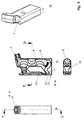
- Fig. 5
- eine Explosionsdarstellung der Einzelteile des erfindungsgemäßen atmungskontrollierten Inhalationsgerätes.
- Fig. 1a
- a front view of an inhalation device according to the invention in the idle state with the mouthpiece open;
- Fig. 1b
- a sectional view taken along line AA of Fig. 1a;
- Fig. 1c
- a sectional view taken along line BB of Fig. 2b;
- Fig. 1d
- a perspective view of the inhalation device according to the invention according to Fig. 1a - 1c;
- Fig. 2a
- a front view of an inhalation device according to the invention in the idle state with the mouthpiece closed;
- Fig. 2b
- a sectional view taken along line AA of FIG. 2a;
- Fig. 2c
- a sectional view taken along line BB of Fig. 2b;
- Fig. 2d
- a perspective view of the inhalation device according to the invention according to Fig. 2a - 2c;
- Fig. 3a
- a front view of an inhalation device according to the invention in the ready-to-inhalation state with the mouthpiece open;
- Fig. 3b
- a sectional view taken along line AA of Fig. 3a;
- Fig. 3c
- a sectional view taken along line BB of Fig. 3b;
- Fig. 3d
- a perspective view of the inhalation device according to the invention according to Fig. 3a - 3c;
- Fig. 4a
- a front view of an inhalation device according to the invention in the ready-to-inhalation state with the mouthpiece closed;
- Fig. 4b
- a sectional view taken along line AA of Fig. 4a;
- Fig. 4c
- a sectional view taken along line BB of Fig. 4b;
- Fig. 4d
- a perspective view of the inhalation device according to the invention according to Fig. 4a - 4c;
- Fig. 5
- an exploded view of the individual parts of the breath-controlled inhalation device according to the invention.
Wie in den Fig. 2a-d und 3a-d gezeigt, wird die Vorratskammer 4
sowohl im unbenutzten als auch im benutzen Zustand durch einen
als Schieber 13 (gesondert gezeigt in Fig. 5) ausgestalteten
Dosierförderer 7 (ebenfalls gesondert dargestellt in Fig. 5) im
wesentlichen ständig verschlossen gehalten. Ein Eindringen von
externer Feuchtigkeit oder Verunreinigungen kann somit in
Hinblick auf das in der Vorratskammer befindliche Trockenpulver
nahezu ausgeschlossen werden.As shown in FIGS. 2a-d and 3a-d, the
Der Dosierförderer 7 weist eine quer verlaufende Dosierbohrung
14 (gezeigt in Fig. 1b) zur Aufnahme des Trockenpulvers auf.
Vor dem Beginn des Inhalationsvorganges befindet sich die
Dosierbohrung 14 in der Vorratskammer 4. Eine Kappe 16 (gesondert
dargestellt in Fig. 5) schützt das Mundstück 3 hygienisch.
Das Inhalationsgerät 1 wird, nachdem die Kappe 16 entfernt
wurde (Fig. 1a und b), senkrecht mit dem Mundstück 3 nach
oben vom Mund entfernt gehalten. Nachdem der Mutzer zunächst
unter Vermeidung eines Kontakts mit dem Mundstück - d.h. ohne
in das Mundstück 3 zu blasen - tief ausgeatmet hat, umschließt
er daraufhin das Mundstück 3 mit den Lippen. Um den
Inhalationsvorgang zu starten und den Dosierförderer 7 in die
Dosierposition zu versetzen, wird dieser entgegen einer durch
eine in Fig. 5 gesondert dargestellten Feder 15 erzeugten Kraft
nach unten gedrückt (Fig. 3b und 3d, sowie Fig. 4b und 4d).The
Die Dosierbohrung 14 befindet sich nun unmittelbar vor einem ansteigenden Einzugsbereich
11 der Luftführungseinheit 5 (Fig. 4b und 3b).
Dadurch, dass die Vorratskammer 4 mit dem Dosierförderer 7
derart gekoppelt ist, dass dieser in einen Übergabebereich 6
vor dem Einzugsbereich eintaucht und die vorgegebenen Menge an Trockenpulver unmittelbar
am Anfang der Luftführungseinheit 5 positionierbar ist,
wird gewährleistet, dass es nicht zu einem ungewollten Verlust
der Portionierung vor oder während der Inhalation kommt.The metering bore 14 is now immediately in front of an increasing
Der Nutzer atmet nun so tief wie möglich durch den Mund ein. The user now breathes in as deeply as possible through the mouth.
Durch einen im Gehäuse 2 befindlichen Lufteinlass 12, der -
wie in Fig. 3b dargestellt - stromab gegenüber dem Einzugsbereich
11 angeordnet ist, wird Luft angesaugt und es entsteht
ein Luftetrom innerhalb des Inhalationsgerätes 1. Dieser trägt
die Partikel des Trockenpulvers über die Dosierbohrung 14 durch
den Übergabe- und Einzugsbereich 6, 11 und schließlich durch
die Luftführungseinheit 5 bis es zu einem Austritt der Partikel
durch das Mundstück 3 direkt in die Atemwege des Nutzers kommt.Through an
Wird der Inhalationsvorgang abgebrochen oder unterbrochen, so
wird das restliche in der Dosierbohrung 14 befindliche Trockenpulver
in die Vorratskammer 4 zurückbefördert, indem die Feder
den Dosierförderer in die Ausgangslage versetzt, oder fällt aus
dem Einzugsbereich heraus und steht damit bei einem weiteren
Inhalationsvorgang nicht mehr zur Verfügung. Auf diese Weise
wird die Gefahr einer Doppeldosierung vermieden.If the inhalation process is interrupted or interrupted, do so
the remaining dry powder located in the metering bore 14
transported back to the
Die infolge der Atmung angesaugte Atemluft wird derart durch die - in Fig. 5 gesondert dargestellte - Luftführungseinheit geführt, dass abwechselnd eine Beschleunigung und ein nachfolgendes Abbremsen des Luftstromes bei gleichzeitiger Verwirbelung und Änderung der Strömungsrichtung erfolgt.The breathing air sucked in as a result of breathing is thus through the air guide unit - shown separately in Fig. 5 that led an alternating acceleration and a subsequent one Decelerating the air flow with simultaneous swirling and change in flow direction.
Ermöglicht wird dies dadurch, dass die Luftführungseinheit 5
aus einem im wesentlichen zylindrischen Grundkörper 9 besteht,
der wechselweise mit kugelkalottenähnlichen Einbuchtungen 10
versehen ist, die sich von jeweils gegenüberliegenden Wandungen
des Grundkörpers 9 in den Strömungskanal 8 der Luft erstrecken.This is made possible by the fact that the
Die Luftführungseinheit 5 kann einstückig oder mehrstückig
ausgebildet sein, wobei sich Glas oder Kunststoff als kostengünstige
Materialien als besonders geeignet erwiesen haben.
Selbstverständlich können auch andere geeignete Materialien,
beispielsweise Metalle für die Herstellung der Luftführungseinheit
verwendet werden. The
Die Beschleunigung der Luftströmung wird dabei durch Querschnittsverengungen
in der Luftführungseinheit 5 vorgenommen,
die sich abwechselnd auf jeweils gegenüberliegenden Seiten in
der Luftführungseinheit 5 befinden. Die so ausgestaltete Luftführungseinheit
5 erlaubt eine sehr effektive und vollständige
Verteilung des Trockenpulvers während des Inhalationsvorganges,
da die angesaugte Luft zirkuliert und die aufsteigenden
Partikel optimal miteinander vermischt werden können.The acceleration of the air flow is due to narrowing of the cross-section
made in the
Durch die Anreicherung der Partikelströme mit kinetischer Energie wird deren Bewegungs- und Verteilungsleistung erhöht und ein etwaiger schwerkraftbedingter Energieverlust kompensiert, was den Verwirbelungseffekt insgesamt verbessert. By enriching the particle flows with kinetic Energy increases their movement and distribution performance and compensates for any loss of energy due to gravity, which improves the swirl effect overall.
- 11
- Inhalationsgerätinhaler
- 22
- Gehäusecasing
- 33
- Mundstückmouthpiece
- 44
- Vorratskammerstoreroom
- 55
- LuftführungseinheitAir distribution unit
- 66
- ÜbergabebereichTransfer area
- 77
- Dosierförderermetering conveyor
- 88th
- Strömungskanalflow channel
- 99
- Grundkörperbody
- 1010
- Einbuchtungindentation
- 1111
- Einzugsbereichcatchment area
- 1212
- Lufteinlaßair intake
- 1313
- Schieberpusher
- 1414
- Dosierbohrungmetering bore
- 1515
- Federfeather
- 1616
- Kappecap
Claims (6)
- Breathing-controlled inhalation device for dry powder, particularly of dry powder mixed with medicines, consisting of a casing with a mouthpiece (3), a reservoir (4) for the dry powder located in the casing (2), as well as an air guiding unit (5) between a transfer area for the dry powder and the mouthpiece(3), whereby the reservoir (4) is connected to a dosing conveyor (7) which dips in the transfer area (6) in such a way that a predetermined amount of dry powder can be positioned directly at the beginning of the air guiding unit (5) and that the attached air guiding unit (5) has an air-flow channel (8) which is provided alternately with narrowings and subsequent enlargements, characterized in that air guiding unit (5) consists of an essentially cylindrical central component (9), characterized in that it is provided alternately with semi-spherical indentations (10) which reach from opposite walls of the central component (9) into the air-flow channel (8), in that the air-flow channel (8) has a rising inhalation area (11) in the application position of the inhalation device (1), immediately following the transfer area (6).
- Breathing-controlled inhalation device according to claim 1, characterized in that the casing (2) is equipped with an air inlet (12), which is arranged downwards opposite the inhalation area (11).
- Breathing-controlled inhalation device according to claim 1, characterized in that the reservoir (4) opposite the inhalation area (11) is locked by means of the dosing conveyor (7) being designed as a flat slide (13), which has a laterally positioned dosing drill hole (14) for taking in the dry powder, in that the dosing drill hole (14) is located inside the reservoir (4) in its closed state and in dosing position immediately in front of the inhalation area (11) of the air guiding unit (5) and that the slide (13) generally keeps the reservoir (4) shut.
- Breathing-controlled inhalation device according to claim 3, characterized in that the slide is held in a spring-loaded start position, in which the reservoir (4) is locked and that the slide (13) is moveable against a spring resistance in the dosing position.
- Breathing-controlled inhalation device according to one of the claims 1 to 4, characterized in that the air guiding unit (5) has a single-part or multi-part design.
- Breathing-controlled inhalation device according to one of the claims 1 to 5, characterized in that the air guiding unit (5) is manufactured from glass, plastic or another suitable material.
Applications Claiming Priority (5)
| Application Number | Priority Date | Filing Date | Title |
|---|---|---|---|
| DE19948289 | 1999-10-06 | ||
| DE19948289 | 1999-10-06 | ||
| DE10027631A DE10027631B4 (en) | 1999-10-06 | 2000-06-06 | Breath-controlled dry powder inhaler and method for uniformly distributing the dry powder in air |
| DE10027631 | 2000-06-06 | ||
| PCT/DE2000/003527 WO2001024857A1 (en) | 1999-10-06 | 2000-10-06 | Breathing-controlled inhalation device for dry powder and method for the even distribution of said dry powder in the air |
Publications (2)
| Publication Number | Publication Date |
|---|---|
| EP1220700A1 EP1220700A1 (en) | 2002-07-10 |
| EP1220700B1 true EP1220700B1 (en) | 2003-04-09 |
Family
ID=26005955
Family Applications (1)
| Application Number | Title | Priority Date | Filing Date |
|---|---|---|---|
| EP00982968A Expired - Lifetime EP1220700B1 (en) | 1999-10-06 | 2000-10-06 | Breathing-controlled inhalation device for dry powder |
Country Status (12)
| Country | Link |
|---|---|
| US (1) | US6729328B2 (en) |
| EP (1) | EP1220700B1 (en) |
| JP (1) | JP2003511107A (en) |
| CN (1) | CN1157236C (en) |
| AT (1) | ATE236676T1 (en) |
| AU (1) | AU774573B2 (en) |
| CA (1) | CA2390111C (en) |
| DK (1) | DK1220700T3 (en) |
| ES (1) | ES2195948T3 (en) |
| HK (1) | HK1049452B (en) |
| PT (1) | PT1220700E (en) |
| WO (1) | WO2001024857A1 (en) |
Cited By (1)
| Publication number | Priority date | Publication date | Assignee | Title |
|---|---|---|---|---|
| US10737045B2 (en) | 2003-08-28 | 2020-08-11 | Optinose As | Delivery devices |
Families Citing this family (48)
| Publication number | Priority date | Publication date | Assignee | Title |
|---|---|---|---|---|
| US9006175B2 (en) | 1999-06-29 | 2015-04-14 | Mannkind Corporation | Potentiation of glucose elimination |
| JP4290009B2 (en) * | 2001-11-22 | 2009-07-01 | フライドリング・アンゲラ | Inhaler controlled by breathing system for dry powder |
| WO2003080149A2 (en) | 2002-03-20 | 2003-10-02 | Mannkind Corporation | Inhalation apparatus |
| EP1452198A4 (en) | 2002-10-11 | 2006-11-02 | Otsuka Pharma Co Ltd | Powder inhalation device |
| EP1488819A1 (en) * | 2003-06-16 | 2004-12-22 | Rijksuniversiteit te Groningen | Dry powder inhaler and method for pulmonary inhalation of dry powder |
| EP1720659A1 (en) * | 2004-02-24 | 2006-11-15 | Boehringer Ingelheim International Gmbh | Atomiser |
| JP5078014B2 (en) | 2004-08-20 | 2012-11-21 | マンカインド コーポレイション | Catalytic reaction of diketopiperazine synthesis. |
| HUE026797T2 (en) | 2004-08-23 | 2016-07-28 | Mannkind Corp | Diketopiperazine salts for drug delivery |
| KR20120060245A (en) | 2005-09-14 | 2012-06-11 | 맨카인드 코포레이션 | Method of drug formulation based on increasing the affinity of crystalline microparticle surfaces for active agents |
| EP2497484A3 (en) | 2006-02-22 | 2012-11-07 | MannKind Corporation | A method for improving the pharmaceutic properties of microparticles comprising diketopiperazine and an active agent |
| WO2009067549A1 (en) * | 2007-11-19 | 2009-05-28 | Allegiance Corporation | Patient interface assembly for respiratory therapy |
| EP2534957B1 (en) | 2007-12-14 | 2015-05-27 | AeroDesigns, Inc | Delivering aerosolizable products |
| EP2077132A1 (en) | 2008-01-02 | 2009-07-08 | Boehringer Ingelheim Pharma GmbH & Co. KG | Dispensing device, storage device and method for dispensing a formulation |
| EP3281663B8 (en) | 2008-06-13 | 2022-09-21 | MannKind Corporation | Breath powered dry powder inhaler for drug delivery |
| US8485180B2 (en) | 2008-06-13 | 2013-07-16 | Mannkind Corporation | Dry powder drug delivery system |
| US9364619B2 (en) | 2008-06-20 | 2016-06-14 | Mannkind Corporation | Interactive apparatus and method for real-time profiling of inhalation efforts |
| TWI494123B (en) | 2008-08-11 | 2015-08-01 | Mannkind Corp | Use of ultrarapid acting insulin |
| US8314106B2 (en) | 2008-12-29 | 2012-11-20 | Mannkind Corporation | Substituted diketopiperazine analogs for use as drug delivery agents |
| CA2754595C (en) | 2009-03-11 | 2017-06-27 | Mannkind Corporation | Apparatus, system and method for measuring resistance of an inhaler |
| EP2662472B1 (en) | 2009-03-31 | 2019-02-27 | Boehringer Ingelheim International Gmbh | Method for coating a surface of a component |
| US9265910B2 (en) | 2009-05-18 | 2016-02-23 | Boehringer Ingelheim International Gmbh | Adapter, inhalation device, and nebulizer |
| WO2010144789A2 (en) | 2009-06-12 | 2010-12-16 | Mannkind Corporation | Diketopiperazine microparticles with defined specific surface areas |
| CA2778698A1 (en) | 2009-11-03 | 2011-05-12 | Mannkind Corporation | An apparatus and method for simulating inhalation efforts |
| WO2011064164A1 (en) | 2009-11-25 | 2011-06-03 | Boehringer Ingelheim International Gmbh | Nebulizer |
| US10016568B2 (en) | 2009-11-25 | 2018-07-10 | Boehringer Ingelheim International Gmbh | Nebulizer |
| WO2011064163A1 (en) | 2009-11-25 | 2011-06-03 | Boehringer Ingelheim International Gmbh | Nebulizer |
| AU2011271097B2 (en) | 2010-06-21 | 2014-11-27 | Mannkind Corporation | Dry powder drug delivery system and methods |
| EP2585151B1 (en) | 2010-06-24 | 2018-04-04 | Boehringer Ingelheim International GmbH | Nebulizer |
| WO2012130757A1 (en) | 2011-04-01 | 2012-10-04 | Boehringer Ingelheim International Gmbh | Medical device comprising a container |
| CN105667994B (en) | 2011-04-01 | 2018-04-06 | 曼金德公司 | Blister package for pharmaceutical kit |
| US9827384B2 (en) | 2011-05-23 | 2017-11-28 | Boehringer Ingelheim International Gmbh | Nebulizer |
| WO2012174472A1 (en) | 2011-06-17 | 2012-12-20 | Mannkind Corporation | High capacity diketopiperazine microparticles |
| KR20140095483A (en) | 2011-10-24 | 2014-08-01 | 맨카인드 코포레이션 | Methods and compositions for treating pain |
| WO2013152894A1 (en) | 2012-04-13 | 2013-10-17 | Boehringer Ingelheim International Gmbh | Atomiser with coding means |
| DK2872205T3 (en) | 2012-07-12 | 2017-02-27 | Mannkind Corp | DRY POWDER FORMAL ADMINISTRATION SYSTEM |
| WO2014066856A1 (en) | 2012-10-26 | 2014-05-01 | Mannkind Corporation | Inhalable influenza vaccine compositions and methods |
| KR102499439B1 (en) | 2013-03-15 | 2023-02-13 | 맨카인드 코포레이션 | Microcrystalline diketopiperazine compositions and methods |
| WO2015010092A1 (en) | 2013-07-18 | 2015-01-22 | Mannkind Corporation | Heat-stable dry powder pharmaceutical compositions and methods |
| JP2016530930A (en) | 2013-08-05 | 2016-10-06 | マンカインド コーポレイション | Ventilation device and method |
| JP6643231B2 (en) | 2013-08-09 | 2020-02-12 | ベーリンガー インゲルハイム インターナショナル ゲゼルシャフト ミット ベシュレンクテル ハフツング | Nebulizer |
| EP2835146B1 (en) | 2013-08-09 | 2020-09-30 | Boehringer Ingelheim International GmbH | Nebulizer |
| WO2015148905A1 (en) | 2014-03-28 | 2015-10-01 | Mannkind Corporation | Use of ultrarapid acting insulin |
| PE20161564A1 (en) | 2014-05-07 | 2017-01-25 | Boehringer Ingelheim Int | NEBULIZER, INDICATOR DEVICE AND CONTAINER |
| ES2874029T3 (en) | 2014-05-07 | 2021-11-04 | Boehringer Ingelheim Int | Nebulizer |
| CA2948071C (en) | 2014-05-07 | 2022-08-30 | Boehringer Ingelheim International Gmbh | Container, nebulizer and use |
| US10561806B2 (en) | 2014-10-02 | 2020-02-18 | Mannkind Corporation | Mouthpiece cover for an inhaler |
| CN106237462A (en) * | 2016-08-08 | 2016-12-21 | 中山市美捷时包装制品有限公司 | A kind of quantitative chemical supply machine structure for depot powder inhaler |
| CN106267484A (en) * | 2016-08-08 | 2017-01-04 | 中山市美捷时包装制品有限公司 | A kind of quantitative feeding mechanism of powder inhaler |
Family Cites Families (11)
| Publication number | Priority date | Publication date | Assignee | Title |
|---|---|---|---|---|
| DE4004904A1 (en) * | 1990-02-16 | 1990-09-13 | Gerhard Brendel | DRUM APPLICATOR |
| GB9015522D0 (en) * | 1990-07-13 | 1990-08-29 | Braithwaite Philip W | Inhaler |
| EP0558879B1 (en) * | 1992-03-04 | 1997-05-14 | Astra Aktiebolag | Disposable inhaler |
| DE4340768A1 (en) | 1993-11-30 | 1995-06-01 | Bayer Ag | Inhalation device |
| FI942196A (en) * | 1994-05-11 | 1995-11-12 | Orion Yhtymae Oy | powder inhaler |
| US5483954A (en) * | 1994-06-10 | 1996-01-16 | Mecikalski; Mark B. | Inhaler and medicated package |
| EA001016B1 (en) * | 1996-01-03 | 2000-08-28 | Глаксо Груп Лимитед | Inhalation device |
| US5699789A (en) * | 1996-03-11 | 1997-12-23 | Hendricks; Mark R. | Dry powder inhaler |
| SE9700421D0 (en) * | 1997-02-07 | 1997-02-07 | Astra Ab | Single dose inhalation I |
| AU5860098A (en) * | 1997-12-23 | 1999-07-19 | Euro-Celtique S.A. | Particle separator for an inhaler |
| DE19825434C2 (en) | 1998-01-30 | 2002-03-28 | Ig Spruehtechnik Gmbh | Inhaler for powdered medication |
-
2000
- 2000-10-06 AU AU19928/01A patent/AU774573B2/en not_active Ceased
- 2000-10-06 CN CNB008139032A patent/CN1157236C/en not_active Expired - Fee Related
- 2000-10-06 AT AT00982968T patent/ATE236676T1/en not_active IP Right Cessation
- 2000-10-06 EP EP00982968A patent/EP1220700B1/en not_active Expired - Lifetime
- 2000-10-06 WO PCT/DE2000/003527 patent/WO2001024857A1/en active IP Right Grant
- 2000-10-06 JP JP2001527856A patent/JP2003511107A/en active Pending
- 2000-10-06 CA CA002390111A patent/CA2390111C/en not_active Expired - Fee Related
- 2000-10-06 DK DK00982968T patent/DK1220700T3/en active
- 2000-10-06 ES ES00982968T patent/ES2195948T3/en not_active Expired - Lifetime
- 2000-10-06 PT PT00982968T patent/PT1220700E/en unknown
-
2002
- 2002-04-04 US US10/117,762 patent/US6729328B2/en not_active Expired - Fee Related
-
2003
- 2003-01-10 HK HK03100269.1A patent/HK1049452B/en not_active IP Right Cessation
Cited By (1)
| Publication number | Priority date | Publication date | Assignee | Title |
|---|---|---|---|---|
| US10737045B2 (en) | 2003-08-28 | 2020-08-11 | Optinose As | Delivery devices |
Also Published As
| Publication number | Publication date |
|---|---|
| AU774573B2 (en) | 2004-07-01 |
| JP2003511107A (en) | 2003-03-25 |
| CA2390111C (en) | 2007-08-07 |
| ES2195948T3 (en) | 2003-12-16 |
| HK1049452B (en) | 2003-10-03 |
| CA2390111A1 (en) | 2001-04-12 |
| CN1157236C (en) | 2004-07-14 |
| US6729328B2 (en) | 2004-05-04 |
| HK1049452A1 (en) | 2003-05-16 |
| CN1378469A (en) | 2002-11-06 |
| EP1220700A1 (en) | 2002-07-10 |
| US20020129817A1 (en) | 2002-09-19 |
| WO2001024857A1 (en) | 2001-04-12 |
| ATE236676T1 (en) | 2003-04-15 |
| AU1992801A (en) | 2001-05-10 |
| DK1220700T3 (en) | 2003-08-04 |
| PT1220700E (en) | 2003-08-29 |
Similar Documents
| Publication | Publication Date | Title |
|---|---|---|
| EP1220700B1 (en) | Breathing-controlled inhalation device for dry powder | |
| DE60035911T2 (en) | dry powder inhaler | |
| DE69929539T2 (en) | MEDICAMENT DISCHARGE DEVICE IN THE FORM OF AN INHALER | |
| EP0547429B1 (en) | Powder inhaler | |
| DE10300032B3 (en) | Inhaler for powdered medicament has pivoted inhalation tube which shuts off powder supply when in out-of-use position, and doses powder into airflow when in use | |
| DE69824300T2 (en) | dry powder inhaler | |
| DE69723156T2 (en) | Regulated flow inhalers | |
| DE69633645T2 (en) | Device for administering medicaments | |
| EP0147755B1 (en) | Inhalator | |
| EP0667793B1 (en) | Method and device for producing an aerosol from a substance in powder form | |
| DE69832679T2 (en) | Device for the administration of a drug in aerosol form | |
| EP1993644B1 (en) | Inhalator for powdery substances | |
| DE60121144T2 (en) | AN INHALATION DEVICE | |
| EP0167581B1 (en) | Inhalation device | |
| EP0799646B1 (en) | Dosing device for flowing media such as air-powder dispersion | |
| DE102005010965B3 (en) | Medical inhaler for personal use, comprises a mixing channel with an outlet with a medicament injection area that is designed to be flush with the surface of the channel to less than a millimeter (mm) and ideally less than a tenth of a mm | |
| DE60131760T2 (en) | DEVICE FOR THE ADMINISTRATION OF PHYSIOLOGICALLY ACTIVE ACTIVE IN POWDER FORM | |
| DE69918325T2 (en) | BREATHABLE AEROSOL DISPENSERS | |
| EP0844007A2 (en) | Product dispenser | |
| EP0505321A2 (en) | Inhaler | |
| EP2709702B1 (en) | Inhalation pen | |
| EP1769818B1 (en) | Powder inhaler | |
| DE60013799T2 (en) | powder inhaler | |
| DE69824327T2 (en) | inhaler | |
| DE10027631B4 (en) | Breath-controlled dry powder inhaler and method for uniformly distributing the dry powder in air |
Legal Events
| Date | Code | Title | Description |
|---|---|---|---|
| PUAI | Public reference made under article 153(3) epc to a published international application that has entered the european phase |
Free format text: ORIGINAL CODE: 0009012 |
|
| 17P | Request for examination filed |
Effective date: 20020426 |
|
| AK | Designated contracting states |
Kind code of ref document: A1 Designated state(s): AT BE CH CY DE DK ES FI FR GB GR IE IT LI LU MC NL PT SE |
|
| AX | Request for extension of the european patent |
Free format text: AL;LT;LV;MK;RO;SI |
|
| RTI1 | Title (correction) |
Free format text: BREATHING-CONTROLLED INHALATION DEVICE FOR DRY POWDER |
|
| GRAH | Despatch of communication of intention to grant a patent |
Free format text: ORIGINAL CODE: EPIDOS IGRA |
|
| RTI1 | Title (correction) |
Free format text: BREATHING-CONTROLLED INHALATION DEVICE FOR DRY POWDER |
|
| GRAH | Despatch of communication of intention to grant a patent |
Free format text: ORIGINAL CODE: EPIDOS IGRA |
|
| GRAA | (expected) grant |
Free format text: ORIGINAL CODE: 0009210 |
|
| AK | Designated contracting states |
Designated state(s): AT BE CH CY DE DK ES FI FR GB GR IE IT LI LU MC NL PT SE |
|
| PG25 | Lapsed in a contracting state [announced via postgrant information from national office to epo] |
Ref country code: IE Free format text: LAPSE BECAUSE OF NON-PAYMENT OF DUE FEES Effective date: 20030409 |
|
| REG | Reference to a national code |
Ref country code: GB Ref legal event code: FG4D Free format text: NOT ENGLISH |
|
| REG | Reference to a national code |
Ref country code: CH Ref legal event code: EP |
|
| REG | Reference to a national code |
Ref country code: IE Ref legal event code: FG4D Free format text: GERMAN |
|
| REG | Reference to a national code |
Ref country code: GR Ref legal event code: EP Ref document number: 20030402250 Country of ref document: GR |
|
| REG | Reference to a national code |
Ref country code: SE Ref legal event code: TRGR |
|
| REG | Reference to a national code |
Ref country code: CH Ref legal event code: NV Representative=s name: BOVARD AG PATENTANWAELTE |
|
| REG | Reference to a national code |
Ref country code: DK Ref legal event code: T3 |
|
| GBT | Gb: translation of ep patent filed (gb section 77(6)(a)/1977) | ||
| LTIE | Lt: invalidation of european patent or patent extension |
Effective date: 20030409 |
|
| PG25 | Lapsed in a contracting state [announced via postgrant information from national office to epo] |
Ref country code: LU Free format text: LAPSE BECAUSE OF NON-PAYMENT OF DUE FEES Effective date: 20031006 Ref country code: CY Free format text: LAPSE BECAUSE OF FAILURE TO SUBMIT A TRANSLATION OF THE DESCRIPTION OR TO PAY THE FEE WITHIN THE PRESCRIBED TIME-LIMIT Effective date: 20031006 |
|
| PG25 | Lapsed in a contracting state [announced via postgrant information from national office to epo] |
Ref country code: MC Free format text: LAPSE BECAUSE OF NON-PAYMENT OF DUE FEES Effective date: 20031031 |
|
| REG | Reference to a national code |
Ref country code: IE Ref legal event code: FD4D Ref document number: 1220700E Country of ref document: IE |
|
| ET | Fr: translation filed | ||
| REG | Reference to a national code |
Ref country code: ES Ref legal event code: FG2A Ref document number: 2195948 Country of ref document: ES Kind code of ref document: T3 |
|
| PLBE | No opposition filed within time limit |
Free format text: ORIGINAL CODE: 0009261 |
|
| STAA | Information on the status of an ep patent application or granted ep patent |
Free format text: STATUS: NO OPPOSITION FILED WITHIN TIME LIMIT |
|
| 26N | No opposition filed |
Effective date: 20040112 |
|
| PGFP | Annual fee paid to national office [announced via postgrant information from national office to epo] |
Ref country code: NL Payment date: 20081023 Year of fee payment: 9 |
|
| PGFP | Annual fee paid to national office [announced via postgrant information from national office to epo] |
Ref country code: CH Payment date: 20081027 Year of fee payment: 9 Ref country code: DK Payment date: 20081024 Year of fee payment: 9 |
|
| PGFP | Annual fee paid to national office [announced via postgrant information from national office to epo] |
Ref country code: AT Payment date: 20081023 Year of fee payment: 9 Ref country code: ES Payment date: 20081027 Year of fee payment: 9 Ref country code: FI Payment date: 20081027 Year of fee payment: 9 Ref country code: PT Payment date: 20081024 Year of fee payment: 9 |
|
| PGFP | Annual fee paid to national office [announced via postgrant information from national office to epo] |
Ref country code: IT Payment date: 20081027 Year of fee payment: 9 Ref country code: BE Payment date: 20081024 Year of fee payment: 9 Ref country code: SE Payment date: 20081027 Year of fee payment: 9 |
|
| PGFP | Annual fee paid to national office [announced via postgrant information from national office to epo] |
Ref country code: FR Payment date: 20081021 Year of fee payment: 9 |
|
| PGFP | Annual fee paid to national office [announced via postgrant information from national office to epo] |
Ref country code: DE Payment date: 20081216 Year of fee payment: 9 |
|
| PGFP | Annual fee paid to national office [announced via postgrant information from national office to epo] |
Ref country code: GB Payment date: 20081024 Year of fee payment: 9 Ref country code: GR Payment date: 20081031 Year of fee payment: 9 |
|
| REG | Reference to a national code |
Ref country code: PT Ref legal event code: MM4A Free format text: LAPSE DUE TO NON-PAYMENT OF FEES Effective date: 20100406 |
|
| BERE | Be: lapsed |
Owner name: *FRYDLING OFER Effective date: 20091031 Owner name: *ECKARDT ANGELA Effective date: 20091031 Owner name: *GOLDEMANN RAUL Effective date: 20091031 |
|
| REG | Reference to a national code |
Ref country code: NL Ref legal event code: V1 Effective date: 20100501 |
|
| REG | Reference to a national code |
Ref country code: CH Ref legal event code: PL |
|
| EUG | Se: european patent has lapsed | ||
| REG | Reference to a national code |
Ref country code: DK Ref legal event code: EBP |
|
| REG | Reference to a national code |
Ref country code: FR Ref legal event code: ST Effective date: 20100630 |
|
| PG25 | Lapsed in a contracting state [announced via postgrant information from national office to epo] |
Ref country code: DE Free format text: LAPSE BECAUSE OF NON-PAYMENT OF DUE FEES Effective date: 20100501 Ref country code: PT Free format text: LAPSE BECAUSE OF NON-PAYMENT OF DUE FEES Effective date: 20100406 Ref country code: NL Free format text: LAPSE BECAUSE OF NON-PAYMENT OF DUE FEES Effective date: 20100501 Ref country code: FR Free format text: LAPSE BECAUSE OF NON-PAYMENT OF DUE FEES Effective date: 20091102 |
|
| PG25 | Lapsed in a contracting state [announced via postgrant information from national office to epo] |
Ref country code: FI Free format text: LAPSE BECAUSE OF NON-PAYMENT OF DUE FEES Effective date: 20091006 Ref country code: AT Free format text: LAPSE BECAUSE OF NON-PAYMENT OF DUE FEES Effective date: 20091006 |
|
| PG25 | Lapsed in a contracting state [announced via postgrant information from national office to epo] |
Ref country code: GR Free format text: LAPSE BECAUSE OF NON-PAYMENT OF DUE FEES Effective date: 20100504 Ref country code: CH Free format text: LAPSE BECAUSE OF NON-PAYMENT OF DUE FEES Effective date: 20091031 Ref country code: BE Free format text: LAPSE BECAUSE OF NON-PAYMENT OF DUE FEES Effective date: 20091031 Ref country code: LI Free format text: LAPSE BECAUSE OF NON-PAYMENT OF DUE FEES Effective date: 20091031 |
|
| PG25 | Lapsed in a contracting state [announced via postgrant information from national office to epo] |
Ref country code: GB Free format text: LAPSE BECAUSE OF NON-PAYMENT OF DUE FEES Effective date: 20091006 |
|
| PG25 | Lapsed in a contracting state [announced via postgrant information from national office to epo] |
Ref country code: DK Free format text: LAPSE BECAUSE OF NON-PAYMENT OF DUE FEES Effective date: 20091031 |
|
| PG25 | Lapsed in a contracting state [announced via postgrant information from national office to epo] |
Ref country code: IT Free format text: LAPSE BECAUSE OF NON-PAYMENT OF DUE FEES Effective date: 20091006 |
|
| REG | Reference to a national code |
Ref country code: ES Ref legal event code: FD2A Effective date: 20110401 |
|
| PG25 | Lapsed in a contracting state [announced via postgrant information from national office to epo] |
Ref country code: SE Free format text: LAPSE BECAUSE OF NON-PAYMENT OF DUE FEES Effective date: 20091007 |
|
| PG25 | Lapsed in a contracting state [announced via postgrant information from national office to epo] |
Ref country code: ES Free format text: LAPSE BECAUSE OF NON-PAYMENT OF DUE FEES Effective date: 20110322 |
|
| PG25 | Lapsed in a contracting state [announced via postgrant information from national office to epo] |
Ref country code: ES Free format text: LAPSE BECAUSE OF NON-PAYMENT OF DUE FEES Effective date: 20091007 |