EP1220535A2 - Cradle for digital camera - Google Patents
Cradle for digital camera Download PDFInfo
- Publication number
- EP1220535A2 EP1220535A2 EP01310729A EP01310729A EP1220535A2 EP 1220535 A2 EP1220535 A2 EP 1220535A2 EP 01310729 A EP01310729 A EP 01310729A EP 01310729 A EP01310729 A EP 01310729A EP 1220535 A2 EP1220535 A2 EP 1220535A2
- Authority
- EP
- European Patent Office
- Prior art keywords
- digital camera
- cradle
- terminal
- retainer
- shield
- Prior art date
- Legal status (The legal status is an assumption and is not a legal conclusion. Google has not performed a legal analysis and makes no representation as to the accuracy of the status listed.)
- Granted
Links
Images


Classifications
-
- H—ELECTRICITY
- H02—GENERATION; CONVERSION OR DISTRIBUTION OF ELECTRIC POWER
- H02J—CIRCUIT ARRANGEMENTS OR SYSTEMS FOR SUPPLYING OR DISTRIBUTING ELECTRIC POWER; SYSTEMS FOR STORING ELECTRIC ENERGY
- H02J7/00—Circuit arrangements for charging or depolarising batteries or for supplying loads from batteries
- H02J7/0042—Circuit arrangements for charging or depolarising batteries or for supplying loads from batteries characterised by the mechanical construction
- H02J7/0044—Circuit arrangements for charging or depolarising batteries or for supplying loads from batteries characterised by the mechanical construction specially adapted for holding portable devices containing batteries
-
- H—ELECTRICITY
- H04—ELECTRIC COMMUNICATION TECHNIQUE
- H04N—PICTORIAL COMMUNICATION, e.g. TELEVISION
- H04N23/00—Cameras or camera modules comprising electronic image sensors; Control thereof
- H04N23/50—Constructional details
-
- H—ELECTRICITY
- H04—ELECTRIC COMMUNICATION TECHNIQUE
- H04N—PICTORIAL COMMUNICATION, e.g. TELEVISION
- H04N23/00—Cameras or camera modules comprising electronic image sensors; Control thereof
-
- H—ELECTRICITY
- H04—ELECTRIC COMMUNICATION TECHNIQUE
- H04N—PICTORIAL COMMUNICATION, e.g. TELEVISION
- H04N1/00—Scanning, transmission or reproduction of documents or the like, e.g. facsimile transmission; Details thereof
- H04N1/00127—Connection or combination of a still picture apparatus with another apparatus, e.g. for storage, processing or transmission of still picture signals or of information associated with a still picture
-
- H—ELECTRICITY
- H04—ELECTRIC COMMUNICATION TECHNIQUE
- H04N—PICTORIAL COMMUNICATION, e.g. TELEVISION
- H04N2201/00—Indexing scheme relating to scanning, transmission or reproduction of documents or the like, and to details thereof
- H04N2201/0008—Connection or combination of a still picture apparatus with another apparatus
- H04N2201/0034—Details of the connection, e.g. connector, interface
- H04N2201/0048—Type of connection
- H04N2201/0058—Docking-station, cradle or the like
Abstract
Description
- The present invention relates to a cradle for retaining therein a digital camera provided with a plurality of connecting terminals.
- As shown in Fig. 8, there has been conventionally a
digital camera 200 provided with a plurality of connecting terminals such as a charging (power source)terminal 204 and a USB terminal 206 serving as an external device connecting terminal at the lower portion of aside surface 202A of acasing 202. - However, in the above-described configuration, as shown in Fig. 8, the charging
terminal 204 and the USB terminal 206 formed in thedigital camera 200 may be exposed to the outside in the state in which thedigital camera 200 is set in adigital camera cradle 210. In thedigital camera cradle 210, a charging terminal connector and a USB terminal connector, neither shown, are generally formed at a retainingsurface 210A for retaining thedigital camera 200 therein. The charging terminal connector and the USB terminal connector are designed to be connected to a chargingterminal 212 and aUSB terminal 214, respectively, which are formed at alower surface 202B of thecasing 202 of thedigital camera 200.
As a result, with the above-described configuration, thedigital camera 200 is set in thedigital camera cradle 210, and thus both of acharging cord 216 and aUSB cord 218 are connected to thedigital camera 200 via thedigital camera cradle 210. However, another charging cord or a USB cord serving as a personal computer connecting cord may be accidentally connected redundantly to the chargingterminal 204 or the USB terminal 206, respectively. - The present invention has been accomplished in view of the above-described situation. Accordingly, an object of the present invention is to provide a cradle for a digital camera that is capable, when a digital camera is set in the cradle, of preventing redundant connection of connecting cords to those of a plurality of connecting terminals formed in the digital camera that are of kinds that are also connected to connecting terminals provided at the cradle.
- In order to achieve the above-described object, a cradle for a digital camera according to a first aspect of the present invention includes: a retainer for retaining therein a digital camera provided with connecting terminals of a first plurality of kinds; a shield formed at the retainer; and a composite terminal including integratedly formed connecting terminals of a second plurality of kinds, wherein, when the digital camera is set in the cradle, the shield shields, of the connecting terminals of the first plurality of kinds, connecting terminals that are the same kinds as the connecting terminals of the second plurality of kinds.
- Consequently, when the digital camera is set in the retainer in the digital camera cradle, since the shield formed at the retainer shields those of the plurality of connecting terminals formed in the digital camera that are of kinds that are also connected to the connecting terminals provided at the cradle, connecting cords cannot be connected directly to such connecting terminals. As a result, it is possible to prevent redundant connection of connecting cords when the digital camera is set in the digital camera cradle.
- According to a second aspect of the present invention, in the digital camera cradle according to the first aspect of the present invention, the connecting terminals shielded by the shield are a charging terminal and/or an external device connecting terminal.
- Consequently, further according to the first aspect of the present invention, it is possible to prevent redundant connection of a charging cord and/or external device connecting cord to the charging terminal and/or external device connecting terminal of the digital camera.
- According to a third aspect of the present invention, the external device connecting terminal in the digital camera cradle according to the second aspect of the present invention is a personal computer connecting terminal.
- Consequently, further according to the second aspect of the present invention, it is possible to prevent redundant connection of a personal computer connecting cord to the personal computer connecting terminal of the digital camera.
- According to a fourth aspect of the present invention, a predetermined position of the shield is aligned with a set-state comfirmation means formed at the side of the digital camera in the state in which the digital camera is completely set in the retainer, in the digital camera cradle according to any one of the first to third aspects of the present invention.
- Consequently, further according to the first to third aspects of the present invention, since a predetermined position of the shield is aligned with the set-state comfirmation means formed on the side of the digital camera when the digital camera is set in the retainer in the digital camera cradle, it is possible to confirm that the digital camera is completely set in the retainer. As a result, it is possible to prevent a setting deficiency of the digital camera in the digital camera cradle.
-
- Fig. 1 is a perspective view illustrating a state in which a digital camera is set in a digital camera cradle according to a first embodiment of the present invention.
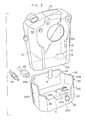
- Fig. 2 is a perspective view illustrating a state in which the digital camera has not yet been set in the digital camera cradle according to the first embodiment of the present invention.
- Fig. 3 is a perspective view showing a lower surface of the digital camera cradle according to the first embodiment of the present invention.
- Fig. 4 is a perspective view showing a rear surface of the digital camera cradle according to the first embodiment of the present invention.
- Fig. 5 is a perspective view illustrating a state in which a leg of the digital camera cradle according to the first embodiment of the present invention is used.
- Fig. 6 is a perspective view illustrating the state in which a digital camera is set in a digital camera cradle according to a modification of the first embodiment of the present invention.
- Fig. 7 is a perspective view illustrating a state in which a digital camera is set in a digital camera cradle according to a second embodiment of the present invention.
- Fig. 8 is a perspective view illustrating the state in which a digital camera is set in a digital camera cradle of the prior art.
- Fig. 9 is a perspective view illustrating a state in which a digital camera is set in a digital camera cradle according to another modification, different from that of Fig. 6, of the first embodiment of the present invention.
-
- A digital camera cradle according to a first embodiment of the present invention will be described hereinafter with reference to Figs. 1 to 5 and 9.
- As shown in Fig. 2, a
composite terminal 14 configured by integrating with each other a charging terminal and a USB terminal that serves as a personal computer connecting terminal is formed at alower surface 12A of acasing 12 of adigital camera 10. Thedigital camera 10 can be inserted from above down into aretainer 22 in a digital camera cradle 20 (in a direction indicated by an arrow A in Fig. 2). - As shown in Fig. 1, a
charging terminal 11 and aUSB terminal 13, which serves as a personal computer connecting terminal or an external device connecting terminal, are formed at a lower portion of aside surface 12B of thecasing 12 of thedigital camera 10. Thecharging terminal 11 and theUSB terminal 13 are used when thedigital camera 10 is not set in thedigital camera cradle 20. Furthermore, an AV (audio/video)terminal 15 is formed above theUSB terminal 13 in thecasing 12 of thedigital camera 10. - As shown in Fig. 2, the
retainer 22 for setting thedigital camera 10 therein is formed at the upper portion of thedigital camera cradle 20. At an outer peripheral portion of the retainer 22 awall 24 is formed upward. The height of thewall 24 is gradually reduced from a highestrear portion 24A tofront portions 24C viaside portions 24B, which serve as a shield. Thefront portions 24C are divided into right and left portions by acutout 26 formed at a width direction central portion. The inner circumferential shape of thewall 24 in theretainer 22 substantially conforms with the outer peripheral shape of a lower portion of thecasing 12 of thedigital camera 10. In the state in which thedigital camera 10 is inserted into theretainer 22 in thedigital camera cradle 20, thelower surface 12A of thecasing 12 of thedigital camera 10 continuously abuts against a predetermined position of abottom 22A of theretainer 22. - At the
bottom 22A of theretainer 22 in thedigital camera cradle 20 is formed acomposite terminal connector 28, which is configured by integrating a charging terminal connector and a USB terminal connector with each other. Thecomposite terminal connector 28 is formed at such a position as to connect to thecomposite terminal 14 of thedigital camera 10 in the state in which thedigital camera 10 is inserted into theretainer 22 of thedigital camera cradle 20. Consequently, when thedigital camera 10 is inserted into theretainer 22 of thedigital camera cradle 20, thecomposite terminal connector 28 of thedigital camera cradle 20 can be automatically connected to thecomposite terminal 14 of thedigital camera 10. - Moreover, in the state in which the
composite terminal connector 28 of thedigital camera cradle 20 is securely connected to thecomposite terminal 14 of thedigital camera 10, that is, when thedigital camera 10 is completely set in theretainer 22 of thedigital camera cradle 20, theside portions 24B of thewall 24 can shield both thecharging terminal 11 and theUSB terminal 13 formed at the lower portion of theside surface 12B of thecasing 12 of thedigital camera 10 and, further, anupper end 13A of theUSB terminal 13, which serves as a set-state comfirmation means, and anupper surface 24D of theside portion 24B are designed to align with each other, as shown in Fig. 1. - As shown in Fig. 2, at a
front surface 20A of thedigital camera cradle 20 is disposed amain switch 29, of a pushbutton type. Depressing themain switch 29 can turn on or off a power source for thedigital camera cradle 20. Additionally, adisplay 30 consisting of an LED is disposed above themain switch 29 at thefront surface 20A of thedigital camera cradle 20 and, further, an upper portion of thedisplay 30 is exposed at thebottom 22A of theretainer 22. - As shown in Fig. 3, a
deep cavity 32 is formed at a rear portion of alower surface 20B of thedigital camera cradle 20 and, further, acutout 34 continuous with thecavity 32 is formed at a lower portion of a rear surface 20C of thedigital camera cradle 20. Moreover, acharging terminal 40 and aUSB terminal 42 are formed on avertical wall 32A of thecavity 32 opposite to thecutout 34. Accordingly, acharging cord 44 is connected to thecharging terminal 40, and aUSB cord 46 is connected to theUSB terminal 42, such that thecharging cord 44 and theUSB cord 46 are made to pass through thecutout 34, as shown in Fig. 4. - Also, a
shallow cavity 48 is formed at a front portion of thelower surface 20B of thedigital camera cradle 20, and afoldable leg 50 can be contained in thecavity 48. Theleg 50 is pivotally supported viapins 52 at front portions of right andleft side walls cavity 48, and can therefore be pivoted in directions H indicated by arrows B and C in Fig. 3. Consequently, when theleg 50 is pivoted in the direction indicated by the arrow C from a usage position shown in Fig. 3, theleg 50 is moved to a contained position; in contrast, when theleg 50 is pivoted in the direction indicated by the arrow B from the contained position, theleg 50 is moved to the usage position. When theleg 50 is located at the usage position, as shown in Fig. 5, thefront surface 20A of thedigital camera cradle 20 can be oriented more upwardly than when theleg 50 is located at the contained position (see Fig. 2). - As shown in Fig. 2, the
digital camera cradle 20 includes therein acontrol circuit 51 provided with a microcomputer. Thecontrol circuit 51 is designed to automatically start communications via the USB terminal as soon as it detects an energized state between thecomposite terminal connector 28 and thecomposite terminal 14 after thedigital camera 10 is set in theretainer 22 in thedigital camera cradle 20. - Furthermore, the
control circuit 51 is designed to automatically turn on the power source for thedigital camera 10 when it detects the energized state between thecomposite terminal connector 28 and thecomposite terminal 14 after thedigital camera 10 is set in theretainer 22 in thedigital camera cradle 20, and to automatically turn off the power source for thedigital camera 10 after a predetermined period of time has passed. - Moreover, the
control circuit 51 is designed to automatically turn on the power source for thedigital camera cradle 20 when it detects the energized state between thecomposite terminal connector 28 and thecomposite terminal 14 after thedigital camera 10 is set in theretainer 22 in thedigital camera cradle 20, and to automatically turn off the power source for thedigital camera cradle 20 after a predetermined period of time has passed. - Additionally, the
control circuit 51 is designed to light thedisplay 30, for example, yellow during communications via the USB terminal, and to light thedisplay 30, for example, red during charging by the charging terminal. - Next, explanation will be given of operation of the present embodiment.
- In the present embodiment, when the
digital camera 10 is set in theretainer 22 of thedigital camera cradle 20, thecomposite terminal 14 of thedigital camera 10, which is configured by integrating the charging terminal and the USB terminal with each other, can be automatically connected to the compositeterminal connector 28 formed in theretainer 22 of thedigital camera cradle 20, which is configured by integrating the charging terminal connector and the USB terminal connector with each other. - At this time, since the
side portions 24B of thewall 24 formed at theretainer 22 can shield the chargingterminal 11 and theUSB terminal 13 formed at the lower portion of theside surface 12B of thecasing 12 of thedigital camera 10 in the present embodiment, thecharging cord 44 and theUSB cord 46 cannot be connected directly to the chargingterminal 11 and theUSB terminal 13 of thedigital camera 10 when thedigital camera 10 is set in thedigital camera cradle 20. As a consequence, it is possible to prevent any redundant connection of thecharging cord 44 and/or theUSB cord 46 when thedigital camera 10 is set in thedigital camera cradle 20. - Furthermore, since the
upper end 13A of theUSB terminal 13, which serves as the set-state comfirmation means, and theupper surface 24D of theside portion 24B of thewall 24 are aligned with each other when thedigital camera 10 is set in theretainer 22 in thedigital camera cradle 20 of the present embodiment, it can be confirmed that thedigital camera 10 has been completely set in theretainer 22 in thedigital camera cradle 20. Consequently, it is possible to prevent any setting deficiency of thedigital camera 10 in thedigital camera cradle 20. - Moreover, when the
control circuit 51 detects the energized state between the compositeterminal connector 28 and thecomposite terminal 14 after thedigital camera 10 is set in theretainer 22 in thedigital camera cradle 20 of the present embodiment, communications via the USB terminal can be automatically started, thereby enhancing operability. - Additionally, when the
control circuit 51 detects the energized state between the compositeterminal connector 28 and thecomposite terminal 14 after thedigital camera 10 is set in theretainer 22 in thedigital camera cradle 20 of the present embodiment, thecontrol circuit 51 automatically turns on the power source for thedigital camera 10, and, after a predetermined period of time has passed, automatically turns off the power source for thedigital camera 10, thereby further enhancing operability. - Moreover, in the present embodiment, the
control circuit 51 automatically turns on the power source for thedigital camera cradle 20 when it detects the energized state between the compositeterminal connector 28 and thecomposite terminal 14 after thedigital camera 10 is set in theretainer 22 in thedigital camera cradle 20, and, after a predetermined period of time has passed, automatically turns off the power source for thedigital camera cradle 20, thereby further enhancing operability. - Additionally, in the present embodiment, the
control circuit 51 lights thedisplay 30, for example, yellow during communications via the USB terminal and red during charging by the charging terminal. As a consequence, it is possible to readily confirm whether or not communications are being carried out via the USB terminal. Thus, it is possible to prevent erroneous detachment of thedigital camera 10 from theretainer 22 in thedigital camera cradle 20 during the communications via the USB terminal, and further, to readily confirm whether or not thedigital camera 10 is being electrically charged. Moreover, since the communications indicating means and charging indicating means are integrated into thesingle display 30, the configuration is simple, thereby reducing cost. - Also, the
upper end 13A of theUSB terminal 13 serving as the set-state comfirmation means and theupper surface 24D of theside portion 24B are aligned with each other when thedigital camera 10 is set in theretainer 22 in thedigital camera cradle 20 of the present embodiment, as shown in Fig. 1. However, for example, as shown in Fig. 6, adesign line 70 formed at a lower portion of thefront surface 12C of thecasing 12 of thedigital camera 10 may be used as the set-state comfirmation means instead, and thedesign line 70 may be aligned with a straight line connectingupper surfaces 24E of the right and leftfront portions 24C of thewall 24. - Also, in the present embodiment, the
side portions 24B of thewall 24 formed at theretainer 22 in thedigital camera cradle 20 are configured to shield the chargingterminal 11 and theUSB terminal 13 formed at the lower portion of theside surface 12B of thecasing 12 in thedigital camera 10 when thedigital camera 10 having the chargingterminal 11 and theUSB terminal 13 is set in thedigital camera cradle 20 of the present embodiment. However, theside portions 24B of thewall 24 formed at theretainer 22 in thedigital camera cradle 20 may instead be configured to shield one of the chargingterminal 11 and theUSB terminal 13 in thedigital camera 10, when thedigital camera 10 that is set in thedigital camera cradle 20 has either the chargingterminal 11 or theUSB terminal 13 formed at the lower portion of theside surface 12B of thecasing 12. - Alternatively, although a USB terminal, which is a wire terminal serving as a personal computer connecting terminal, is provided in the
digital camera 10 of the present embodiment, the personal computer connecting terminal is not limited to wire terminals such as USB terminals, and may be, for example, a wireless terminal that uses BLUETOOTH technology or infrared radiation. - Also, the communications indicating means and the charging indicating means are integrated into the
single display 30 and lighting colors are changed in the present embodiment. However, communications and charging may instead be discriminated by variations of lighting or flashing in the same color. Alternatively, thedisplay 30 to serve as the communications indicating means and anotherdisplay 62 to serve as the charging indicating means may be disposed independently of each other in thedigital camera cradle 20, as shown in Fig. 9. - Also, in the present embodiment, the charging terminal connector and the USB terminal connector are integrated into the composite
terminal connector 28 of thedigital camera cradle 20. However, if the charging terminal and the USB terminal, which are formed at thedigital camera 10 side and are used for connection to thedigital camera cradle 20, are instead provided separately from each other, the charging terminal connector and the USB terminal connector may also be provided separately from each other in thedigital camera cradle 20. - Subsequently, description will be given of a second preferred embodiment of a cradle for a digital camera according to the present invention, with reference to Fig. 7.
- Here, constituent members the same as those in the first embodiment are designated by the same reference numerals, and descriptions thereof will accordingly be omitted hereinafter.
- As shown in Fig. 7, an
AV terminal shield 24F extends upward from theside portion 24B of thewall 24 of thedigital camera cradle 20 of the present embodiment. In a state in which thedigital camera 10 is set in thedigital camera cradle 20, theAV terminal shield 24F shields anAV terminal 15 in thedigital camera 10. - Although not shown, an AV terminal is formed substantially at the same location as the charging
terminal 40 and USB terminal 42 (see Fig. 3) in thedigital camera cradle 20. AnAV cord 48 is connected to the AV terminal. - Next, explanation will be given of operation of the present embodiment.
- Functions and effects similar to those of the first embodiment can be produced in the present embodiment. Furthermore, the
AV terminal shield 24F can shield theAV terminal 15 of thedigital camera 10 when thedigital camera 10 is set in thedigital camera cradle 20. As a consequence, theAV cord 48 cannot be connected directly to theAV terminal 15 in thedigital camera 10. Therefore, it is possible to prevent redundant connection of theAV cord 48 when thedigital camera 10 is set in thedigital camera cradle 20. - Although the present invention has been described in detail with respect to the particular embodiments, it is not limited to the above-described embodiments. It will now be apparent to those skilled in the art that other variations and modifications may be made without departing from the scope of the invention.
Claims (10)
- A cradle for a digital camera provided with connecting terminals of a first plurality of kinds, the cradle comprising:wherein, when the digital camera is set in the cradle, the shield shields, of the connecting terminals of the first plurality of kinds, connecting terminals that are of the same kinds as the connecting terminals of the second plurality of kinds.a retainer for retaining therein a digital camera;a shield formed at the retainer; anda composite terminal including integratedly formed connecting terminals of a second plurality of kinds,
- A cradle for a digital camera as claimed in claim 1, wherein the connecting terminals that are shielded by the shield include a charging terminal and an external device connecting terminal.
- A cradle for a digital camera as claimed in claim 2, wherein the external device connecting terminal comprises a personal computer connecting terminal.
- A cradle for a digital camera as claimed in claim 1, wherein the shield comprises an upper end portion and, when the digital camera is completely set in the retainer, the upper end portion of the shield substantially aligns with an upper end portion of the uppermost-positioned connecting terminal of the connecting terminals that are shielded by the shield.
- A cradle for a digital camera as claimed in claim 2, wherein the shield comprises an upper end portion and, when the digital camera is completely set in the retainer, the upper end portion of the shield substantially aligns with an upper end portion of the uppermost-positioned one of the charging terminal and the external device connecting terminal.
- A cradle for a digital camera as claimed in claim 3, wherein the shield comprises an upper end portion and, when the digital camera is completely set in the retainer, the upper end portion of the shield substantially aligns with an upper end portion of the uppermost-positioned one of the charging terminal and the personal computer connecting terminal.
- A cradle for a digital camera as claimed in claim 3, wherein the digital camera further includes an AV terminal, and the shield does not shield the AV terminal when the digital camera is set in the retainer.
- A cradle for a digital camera as claimed in claim 1, wherein the digital camera includes a digital camera side composite terminal having integrally formed therein connecting terminals of kinds corresponding to kinds of the connecting terminals that are shielded by the shield, and the digital camera side composite terminal electrically connects to the composite terminal formed at the cradle when the digital camera is set in the retainer.
- A cradle for a digital camera as claimed in claim 2, wherein the digital camera includes a digital camera side composite terminal having integrally formed therein connecting terminals of kinds corresponding to kinds of the connecting terminals that are shielded by the shield, and the digital camera side composite terminal electrically connects to the composite terminal formed at the cradle when the digital camera is set in the retainer.
- A cradle for a digital camera as claimed in claim 3, wherein the digital camera includes a digital camera side composite terminal having integrally formed therein connecting terminals of kinds corresponding to kinds of the connecting terminals that are shielded by the shield, and the digital camera side composite terminal electrically connects to the composite terminal formed at the cradle when the digital camera is set in the retainer.
Applications Claiming Priority (6)
| Application Number | Priority Date | Filing Date | Title |
|---|---|---|---|
| JP2000388438 | 2000-12-21 | ||
| JP2000388438 | 2000-12-21 | ||
| JP2000388437 | 2000-12-21 | ||
| JP2000388437 | 2000-12-21 | ||
| JP2001316256A JP2002252801A (en) | 2000-12-21 | 2001-10-15 | Cradle for digital camera |
| JP2001316256 | 2001-10-15 |
Publications (3)
| Publication Number | Publication Date |
|---|---|
| EP1220535A2 true EP1220535A2 (en) | 2002-07-03 |
| EP1220535A3 EP1220535A3 (en) | 2004-05-19 |
| EP1220535B1 EP1220535B1 (en) | 2007-02-14 |
Family
ID=27345498
Family Applications (1)
| Application Number | Title | Priority Date | Filing Date |
|---|---|---|---|
| EP01310729A Expired - Lifetime EP1220535B1 (en) | 2000-12-21 | 2001-12-20 | Cradle for digital camera |
Country Status (7)
| Country | Link |
|---|---|
| US (1) | US6950142B2 (en) |
| EP (1) | EP1220535B1 (en) |
| JP (1) | JP2002252801A (en) |
| KR (1) | KR100577595B1 (en) |
| CN (1) | CN1235084C (en) |
| DE (1) | DE60126578T2 (en) |
| TW (1) | TW548967B (en) |
Cited By (4)
| Publication number | Priority date | Publication date | Assignee | Title |
|---|---|---|---|---|
| GB2386005A (en) * | 2002-03-01 | 2003-09-03 | Matsushita Comm Ind Uk Ltd | Battery charging for portable devices with USB links |
| EP1742140A2 (en) * | 2005-07-05 | 2007-01-10 | High Tech Computer Corp. | Cradle for connecting to portable electronic apparatus |
| US7436453B2 (en) | 2003-08-20 | 2008-10-14 | Canon Kabushiki Kaisha | Electronic apparatus and camera having connectors |
| US7675571B2 (en) | 2005-06-29 | 2010-03-09 | Htc Corporation | Cradle for connecting to portable electronic apparatus |
Families Citing this family (29)
| Publication number | Priority date | Publication date | Assignee | Title |
|---|---|---|---|---|
| US7016595B1 (en) * | 1999-05-28 | 2006-03-21 | Nikon Corporation | Television set capable of controlling external device and image storage controlled by television set |
| US7253840B2 (en) * | 2001-06-11 | 2007-08-07 | Fujifilm Corporation | Cradle for digital camera |
| JP3535495B2 (en) * | 2001-12-26 | 2004-06-07 | 株式会社東芝 | Cradle-mounted digital camera, control method thereof, and cradle-mounted digital camera system |
| JP4081541B2 (en) * | 2002-03-11 | 2008-04-30 | 富士フイルム株式会社 | Imaging communication system |
| US7259793B2 (en) * | 2002-03-26 | 2007-08-21 | Eastman Kodak Company | Display module for supporting a digital image display device |
| US7142244B1 (en) * | 2002-08-29 | 2006-11-28 | Sprint Spectrum L.P. | Digital camera with integrated cable storage |
| JP3900083B2 (en) * | 2002-12-24 | 2007-04-04 | 株式会社デンソーウェーブ | Image communication system |
| US7551225B2 (en) * | 2003-12-09 | 2009-06-23 | Sony Ericsson Mobile Communications Ab | Positioning accessory for camera-equipped wireless terminals |
| JP2005323261A (en) * | 2004-05-11 | 2005-11-17 | Olympus Corp | Accessory set |
| US7280854B2 (en) | 2004-06-15 | 2007-10-09 | Olympus Corporation | Portable information terminal cradle apparatus |
| US7411608B1 (en) * | 2004-08-20 | 2008-08-12 | Raymond Wayne Moskaluk | System and method for producing photographic prints |
| KR100771189B1 (en) * | 2005-09-29 | 2007-11-23 | 주식회사 티노스 | GPS device comprising of cradle |
| US7623182B2 (en) * | 2006-04-10 | 2009-11-24 | Hewlett-Packard Development Company, L.P. | Camera interface module |
| US7893990B1 (en) * | 2006-07-31 | 2011-02-22 | Cisco Technology, Inc. | Digital video camera with retractable data connector and resident software application |
| US20080265838A1 (en) * | 2007-04-24 | 2008-10-30 | Saurabh Garg | Battery charging using a USB-ID pin of a USB interface |
| WO2009055744A1 (en) * | 2007-10-26 | 2009-04-30 | Pure Digital Technologies | Charging and use scheme for a hand-held electronics device |
| US7859222B2 (en) * | 2007-12-21 | 2010-12-28 | Steven Woud | Case battery system |
| USD627380S1 (en) | 2009-10-08 | 2010-11-16 | Cisco Technology, Inc. | Digital video camera with a connector |
| JP5628022B2 (en) * | 2009-12-28 | 2014-11-19 | パナソニック株式会社 | Electronic device and power supply control method |
| EP2585301B1 (en) * | 2010-06-24 | 2017-11-01 | Avery Dennison Corporation | Hand-held portable printer |
| USD767377S1 (en) * | 2013-01-31 | 2016-09-27 | Airpressure Bodyforming Gmbh | Mounting bracket |
| US10299400B2 (en) | 2013-02-27 | 2019-05-21 | Innovelis, Inc. | Mounting systems for digital media players |
| USD747379S1 (en) | 2013-10-18 | 2016-01-12 | Wolfcom Enterprises | Body camera |
| USD811994S1 (en) * | 2015-08-13 | 2018-03-06 | Jsp Limited | Battery pack |
| JP1558997S (en) * | 2015-12-25 | 2017-04-10 | ||
| US10575427B2 (en) | 2016-04-18 | 2020-02-25 | Innovelis, Inc. | Mounting systems for digital media players |
| US10117344B2 (en) * | 2017-02-04 | 2018-10-30 | Innovelis, Inc. | Mounting systems for media players |
| US10194544B2 (en) * | 2017-02-04 | 2019-01-29 | Innovelis, Inc. | Mounting systems for media players |
| USD900910S1 (en) * | 2019-02-27 | 2020-11-03 | Axis Ab | Body-worn camera |
Citations (3)
| Publication number | Priority date | Publication date | Assignee | Title |
|---|---|---|---|---|
| EP0624038A1 (en) * | 1993-04-30 | 1994-11-09 | Casio Computer Company Limited | Television telephone apparatus |
| JPH11220691A (en) * | 1998-02-02 | 1999-08-10 | Casio Comput Co Ltd | Picture deposit device and method therefor |
| JP2000152047A (en) * | 1998-11-18 | 2000-05-30 | Scalar Kk | Digital camera |
Family Cites Families (5)
| Publication number | Priority date | Publication date | Assignee | Title |
|---|---|---|---|---|
| US4937676A (en) * | 1989-02-10 | 1990-06-26 | Polariod Corporation | Electronic camera system with detachable printer |
| US6138826A (en) * | 1998-02-02 | 2000-10-31 | Fuji Photo Film Co., Ltd. | Waterproof case for camera |
| US6717762B1 (en) * | 2000-06-09 | 2004-04-06 | Iomega Corporation | Method and apparatus for making a drive compatible with a removable cartridge |
| US20020071035A1 (en) * | 2000-12-07 | 2002-06-13 | Sobol Robert E. | Digital camera docking station |
| JP4340410B2 (en) * | 2001-10-15 | 2009-10-07 | 富士フイルム株式会社 | Cradle for digital camera |
-
2001
- 2001-10-15 JP JP2001316256A patent/JP2002252801A/en active Pending
- 2001-12-20 EP EP01310729A patent/EP1220535B1/en not_active Expired - Lifetime
- 2001-12-20 US US10/023,426 patent/US6950142B2/en not_active Expired - Fee Related
- 2001-12-20 KR KR1020010081579A patent/KR100577595B1/en not_active IP Right Cessation
- 2001-12-20 DE DE60126578T patent/DE60126578T2/en not_active Expired - Lifetime
- 2001-12-21 TW TW090131943A patent/TW548967B/en not_active IP Right Cessation
- 2001-12-21 CN CNB011454369A patent/CN1235084C/en not_active Expired - Fee Related
Patent Citations (3)
| Publication number | Priority date | Publication date | Assignee | Title |
|---|---|---|---|---|
| EP0624038A1 (en) * | 1993-04-30 | 1994-11-09 | Casio Computer Company Limited | Television telephone apparatus |
| JPH11220691A (en) * | 1998-02-02 | 1999-08-10 | Casio Comput Co Ltd | Picture deposit device and method therefor |
| JP2000152047A (en) * | 1998-11-18 | 2000-05-30 | Scalar Kk | Digital camera |
Non-Patent Citations (2)
| Title |
|---|
| PATENT ABSTRACTS OF JAPAN vol. 1999, no. 13, 30 November 1999 (1999-11-30) & JP 11 220691 A (CASIO COMPUT CO LTD), 10 August 1999 (1999-08-10) * |
| PATENT ABSTRACTS OF JAPAN vol. 2000, no. 08, 6 October 2000 (2000-10-06) & JP 2000 152047 A (SCALAR KK), 30 May 2000 (2000-05-30) * |
Cited By (6)
| Publication number | Priority date | Publication date | Assignee | Title |
|---|---|---|---|---|
| GB2386005A (en) * | 2002-03-01 | 2003-09-03 | Matsushita Comm Ind Uk Ltd | Battery charging for portable devices with USB links |
| US7436453B2 (en) | 2003-08-20 | 2008-10-14 | Canon Kabushiki Kaisha | Electronic apparatus and camera having connectors |
| US7675571B2 (en) | 2005-06-29 | 2010-03-09 | Htc Corporation | Cradle for connecting to portable electronic apparatus |
| EP1742140A2 (en) * | 2005-07-05 | 2007-01-10 | High Tech Computer Corp. | Cradle for connecting to portable electronic apparatus |
| EP1742140A3 (en) * | 2005-07-05 | 2007-09-12 | High Tech Computer Corp. | Cradle for connecting to portable electronic apparatus |
| CN100454188C (en) * | 2005-07-05 | 2009-01-21 | 宏达国际电子股份有限公司 | Connection seat of portable electronic device |
Also Published As
| Publication number | Publication date |
|---|---|
| DE60126578D1 (en) | 2007-03-29 |
| KR20020050717A (en) | 2002-06-27 |
| JP2002252801A (en) | 2002-09-06 |
| CN1235084C (en) | 2006-01-04 |
| US6950142B2 (en) | 2005-09-27 |
| TW548967B (en) | 2003-08-21 |
| KR100577595B1 (en) | 2006-05-10 |
| EP1220535A3 (en) | 2004-05-19 |
| CN1360223A (en) | 2002-07-24 |
| EP1220535B1 (en) | 2007-02-14 |
| DE60126578T2 (en) | 2007-07-05 |
| US20020079864A1 (en) | 2002-06-27 |
Similar Documents
| Publication | Publication Date | Title |
|---|---|---|
| US6950142B2 (en) | Cradle for digital camera | |
| EP3675317B1 (en) | Inductive charger with rotatable magnetic mount | |
| US10250056B2 (en) | Multi-function external attachment and safety circuit for a portable power charger | |
| US20150380879A1 (en) | Lighted electrical interconnect assembly | |
| US20020186317A1 (en) | Cradle for digital camera | |
| US6348035B1 (en) | Connection system for electronic endoscope | |
| CN101189548A (en) | Display device | |
| US20140354888A1 (en) | Connection device | |
| KR20090007350A (en) | Modular computer mouse | |
| US11148308B2 (en) | Cleaning and charging station | |
| US20070132880A1 (en) | Stand for digital camera | |
| US7417685B2 (en) | Cradle apparatus for digital camera | |
| US7167207B2 (en) | Cradle apparatus for camera | |
| US6639382B1 (en) | Mobile phone charger with automatic light | |
| CN100578343C (en) | Projection device | |
| KR20170137312A (en) | Micro USB OTG cable | |
| EP1324433A2 (en) | Electric connector | |
| US10593165B2 (en) | Auxiliary unit for sensor units | |
| KR200379697Y1 (en) | A connector for charging of a hand phone | |
| CN1697485A (en) | Stand apparatus and camera system | |
| JP2003087621A (en) | Electronic camera system | |
| US20230396094A1 (en) | Multifunctional Charging and Lighting Device | |
| JP2003075907A (en) | Portable equipment with cradle | |
| US20040081422A1 (en) | Display-provided portable electronic device | |
| JP2005244909A (en) | Charger for terminal |
Legal Events
| Date | Code | Title | Description |
|---|---|---|---|
| PUAI | Public reference made under article 153(3) epc to a published international application that has entered the european phase |
Free format text: ORIGINAL CODE: 0009012 |
|
| AK | Designated contracting states |
Kind code of ref document: A2 Designated state(s): AT BE CH CY DE DK ES FI FR GB GR IE IT LI LU MC NL PT SE TR |
|
| AX | Request for extension of the european patent |
Free format text: AL;LT;LV;MK;RO;SI |
|
| RIN1 | Information on inventor provided before grant (corrected) |
Inventor name: KANAMORI, SHINO, C/O FUJI PHOTO FILM CO., LTD. Inventor name: SOUMI, MITSUO, C/O FUJI PHOTO FILM CO., LTD. |
|
| PUAL | Search report despatched |
Free format text: ORIGINAL CODE: 0009013 |
|
| AK | Designated contracting states |
Kind code of ref document: A3 Designated state(s): AT BE CH CY DE DK ES FI FR GB GR IE IT LI LU MC NL PT SE TR |
|
| AX | Request for extension of the european patent |
Extension state: AL LT LV MK RO SI |
|
| RIC1 | Information provided on ipc code assigned before grant |
Ipc: 7H 04N 5/232 A Ipc: 7H 04N 5/225 B |
|
| 17P | Request for examination filed |
Effective date: 20041026 |
|
| AKX | Designation fees paid |
Designated state(s): DE FR GB |
|
| 17Q | First examination report despatched |
Effective date: 20050210 |
|
| GRAP | Despatch of communication of intention to grant a patent |
Free format text: ORIGINAL CODE: EPIDOSNIGR1 |
|
| GRAS | Grant fee paid |
Free format text: ORIGINAL CODE: EPIDOSNIGR3 |
|
| GRAA | (expected) grant |
Free format text: ORIGINAL CODE: 0009210 |
|
| AK | Designated contracting states |
Kind code of ref document: B1 Designated state(s): DE FR GB |
|
| REG | Reference to a national code |
Ref country code: GB Ref legal event code: FG4D |
|
| RAP2 | Party data changed (patent owner data changed or rights of a patent transferred) |
Owner name: FUJIFILM CORPORATION |
|
| REF | Corresponds to: |
Ref document number: 60126578 Country of ref document: DE Date of ref document: 20070329 Kind code of ref document: P |
|
| ET | Fr: translation filed | ||
| PLBE | No opposition filed within time limit |
Free format text: ORIGINAL CODE: 0009261 |
|
| STAA | Information on the status of an ep patent application or granted ep patent |
Free format text: STATUS: NO OPPOSITION FILED WITHIN TIME LIMIT |
|
| 26N | No opposition filed |
Effective date: 20071115 |
|
| PGFP | Annual fee paid to national office [announced via postgrant information from national office to epo] |
Ref country code: GB Payment date: 20131218 Year of fee payment: 13 Ref country code: DE Payment date: 20131218 Year of fee payment: 13 |
|
| PGFP | Annual fee paid to national office [announced via postgrant information from national office to epo] |
Ref country code: FR Payment date: 20131209 Year of fee payment: 13 |
|
| REG | Reference to a national code |
Ref country code: DE Ref legal event code: R119 Ref document number: 60126578 Country of ref document: DE |
|
| GBPC | Gb: european patent ceased through non-payment of renewal fee |
Effective date: 20141220 |
|
| REG | Reference to a national code |
Ref country code: FR Ref legal event code: ST Effective date: 20150831 |
|
| PG25 | Lapsed in a contracting state [announced via postgrant information from national office to epo] |
Ref country code: DE Free format text: LAPSE BECAUSE OF NON-PAYMENT OF DUE FEES Effective date: 20150701 Ref country code: GB Free format text: LAPSE BECAUSE OF NON-PAYMENT OF DUE FEES Effective date: 20141220 |
|
| PG25 | Lapsed in a contracting state [announced via postgrant information from national office to epo] |
Ref country code: FR Free format text: LAPSE BECAUSE OF NON-PAYMENT OF DUE FEES Effective date: 20141231 |