EP1220433B1 - Netzteil für einen sicherheitsrelevanten Schaltkreis - Google Patents
Netzteil für einen sicherheitsrelevanten Schaltkreis Download PDFInfo
- Publication number
- EP1220433B1 EP1220433B1 EP01128090A EP01128090A EP1220433B1 EP 1220433 B1 EP1220433 B1 EP 1220433B1 EP 01128090 A EP01128090 A EP 01128090A EP 01128090 A EP01128090 A EP 01128090A EP 1220433 B1 EP1220433 B1 EP 1220433B1
- Authority
- EP
- European Patent Office
- Prior art keywords
- power supply
- supply unit
- voltage
- switched
- mode power
- Prior art date
- Legal status (The legal status is an assumption and is not a legal conclusion. Google has not performed a legal analysis and makes no representation as to the accuracy of the status listed.)
- Expired - Lifetime
Links
Images

Classifications
-
- F—MECHANICAL ENGINEERING; LIGHTING; HEATING; WEAPONS; BLASTING
- F23—COMBUSTION APPARATUS; COMBUSTION PROCESSES
- F23D—BURNERS
- F23D14/00—Burners for combustion of a gas, e.g. of a gas stored under pressure as a liquid
- F23D14/46—Details
- F23D14/72—Safety devices, e.g. operative in case of failure of gas supply
-
- F—MECHANICAL ENGINEERING; LIGHTING; HEATING; WEAPONS; BLASTING
- F23—COMBUSTION APPARATUS; COMBUSTION PROCESSES
- F23N—REGULATING OR CONTROLLING COMBUSTION
- F23N2233/00—Ventilators
- F23N2233/06—Ventilators at the air intake
-
- F—MECHANICAL ENGINEERING; LIGHTING; HEATING; WEAPONS; BLASTING
- F23—COMBUSTION APPARATUS; COMBUSTION PROCESSES
- F23N—REGULATING OR CONTROLLING COMBUSTION
- F23N2235/00—Valves, nozzles or pumps
- F23N2235/12—Fuel valves
- F23N2235/14—Fuel valves electromagnetically operated
-
- F—MECHANICAL ENGINEERING; LIGHTING; HEATING; WEAPONS; BLASTING
- F23—COMBUSTION APPARATUS; COMBUSTION PROCESSES
- F23N—REGULATING OR CONTROLLING COMBUSTION
- F23N5/00—Systems for controlling combustion
- F23N5/24—Preventing development of abnormal or undesired conditions, i.e. safety arrangements
-
- F—MECHANICAL ENGINEERING; LIGHTING; HEATING; WEAPONS; BLASTING
- F23—COMBUSTION APPARATUS; COMBUSTION PROCESSES
- F23N—REGULATING OR CONTROLLING COMBUSTION
- F23N5/00—Systems for controlling combustion
- F23N5/26—Details
-
- H—ELECTRICITY
- H02—GENERATION; CONVERSION OR DISTRIBUTION OF ELECTRIC POWER
- H02M—APPARATUS FOR CONVERSION BETWEEN AC AND AC, BETWEEN AC AND DC, OR BETWEEN DC AND DC, AND FOR USE WITH MAINS OR SIMILAR POWER SUPPLY SYSTEMS; CONVERSION OF DC OR AC INPUT POWER INTO SURGE OUTPUT POWER; CONTROL OR REGULATION THEREOF
- H02M3/00—Conversion of DC power input into DC power output
- H02M3/22—Conversion of DC power input into DC power output with intermediate conversion into AC
- H02M3/24—Conversion of DC power input into DC power output with intermediate conversion into AC by static converters
- H02M3/28—Conversion of DC power input into DC power output with intermediate conversion into AC by static converters using discharge tubes with control electrode or semiconductor devices with control electrode to produce the intermediate AC
- H02M3/325—Conversion of DC power input into DC power output with intermediate conversion into AC by static converters using discharge tubes with control electrode or semiconductor devices with control electrode to produce the intermediate AC using devices of a triode or a transistor type requiring continuous application of a control signal
- H02M3/335—Conversion of DC power input into DC power output with intermediate conversion into AC by static converters using discharge tubes with control electrode or semiconductor devices with control electrode to produce the intermediate AC using devices of a triode or a transistor type requiring continuous application of a control signal using semiconductor devices only
Definitions
- the present invention relates to a method for sizing a power supply for a safety-related circuit.
- controls for gas appliances with automatic gas burner control systems and low-voltage actuators are operated with conventional power supplies with relatively large transformers.
- the power supply for the fan, the fan and / or the gas valves is disconnected from the power supply of the controller and the gas burner control. This results in two power supplies and due to the 50-Hz feed into the transformer relatively large and expensive transformers and the overhead for a second power supply and overall lower efficiency.
- Automatic gas burner control systems require a voltage feed with tolerances that are to be maintained relatively precisely. If there is an undervoltage in the supply, then the automatic burner control is switched off due to an undervoltage detection. If, however, overvoltages occur in the power supply units, destruction of the automatic burner control unit can occur and thus uncontrolled conditions of the heater controlled by it.
- the AT 396 636 B shows a voltage monitoring of a gas burner control, which causes the automatic burner control to close the gas path, but not the Voltage limited. In this case, the automatic burner control system must still ensure that it is not damaged due to increased voltages.
- the US 4,236,187 describes a monitoring circuit for a switching power supply, which engages with increased output voltage in the control of the power supply by the oscillator frequency is reduced. This is not to be regarded as fail-safe.
- the present invention is therefore based on the object of dimensioning a relatively inexpensive and uncomplicated power supply that excludes overvoltages to be powered gas burner with safety.
- the transformer of the power supply can be made smaller in consequence of the clocking in the primary circuit and thus cheaper.
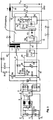
- a feeding AC voltage network 1 with a nominal voltage level of 230 V is connected via 2 lines 2 and 3 to a line filter 4.
- This line filter is connected via 2 further lines 5 and 6 with a rectifier 7.
- On the output side of this rectifier is parallel to the lines 8 and 9 connected a smoothing capacitor C1.
- the two lines 8 and 9 lead once to a branch point 10 and to another branch point 11.
- a resistor R6 is connected, which leads to an auxiliary power supply 12.
- the second output of the auxiliary voltage supply is connected via a line 13 to the branch point 11.
- the branching point 11 is connected via the continuing line 9 with a further branching point 14. From this leads a line 15 to an input S of a switching regulator IC11.
- Another input D of the switching regulator is connected via a line 16 to a coil L1 of a transformer U1.
- the line 13 connects a ground input of the auxiliary power supply to the branch point 11.
- the resistor R6 is connected to the input U2 of the auxiliary power supply.
- One Another input I1 of the auxiliary voltage supply is connected via a line 17 to a coil L3 of the transformer U1, the other side is connected via a line 18 to the branch point 14.
- a line 30 connects inputs of the auxiliary power supply and the switching regulator.
- a coil L2 of the transformer U1 is connected to a ground line and another line 19.
- a forward-biased diode D1 is inserted, followed by a coil L4, between the two is a branch point 21.
- a branch point 20 is connected via a line 26 to a feedback circuit, which leads on its other side to an input FB of the switching regulator.
- a smoothing capacitor C2 is connected, which leads on its other side to a branch point 23 in the ground line.
- a line 24 leads to a next branch point 25, the two branch points 14 and 25 are connected via a capacitor C7 / 8.
- the feedback circuit is connected to the branch point 25 with a third input.
- the coil L4 leads to a next branch point 27, to which a capacitor C3 is connected, which is connected on the other side at a branch point 28 to the ground line.
- a connected load here a gas burner GFA
- the coil L1 is connected via a line 29 to the branch point 8, in which the branch point 10 is located.
- a motor 45 of a blower 46 is connected via two lines 43 and 44.
- a gas valve 49 with its coil 50 and the actual valve 51 is connected via lines 47 and 48, as it is in the course of a gas supply line 52 to a burner, not shown.
- To this burner will be Fresh air is conveyed via the blower 46 or, if the blower is in the exhaust duct, the access of fresh air to the burner is promoted.
- Burners and heat exchangers, not shown, are designed so that the heater you essentially determined in condensing operation, ie as a condensing boiler works.
- FIG. 1 and 3 There are certain differences, which result from the fact that in the block diagrams 4, 7, IC11 and feedback different elements are summarized, which then in detail in the circuit diagram of FIG. 3 appear.
- the line filter 4 additionally has a protective conductor SL.
- the protective conductor SL is connected via a capacitor C12 to the line 3 and via a capacitor C13 to the line 2.
- a varistor R16 Between the lines 2 and 3 is a varistor R16, then the two lines 2 and 3 are passed through coils of a current-compensated inductor L5, which is then connected via lines 5 and 6 to the rectifier 7.
- This consists of 4 diodes D5, D6, D7 and D8, at whose output the capacitor C1 is located.
- the auxiliary power supply 12 has a Zener diode D10, which connects the branch point 11 with a branch point 32. This forms the entrance U2. From the branch point 32, a line 33 leads to a further branch point 34. Connected to this is a series connection of a resistor R30 to a capacitor C8, the capacitor being galvanically connected to the branch point 11 on the side facing away from the resistor. At a connection point 35 between the resistor R30 and the capacitor C8, another capacitor C9 is connected in parallel to the capacitor C8.
- the branch point 34 is connected to the output I1 via a series connection of a resistor R8 with a reverse-connected diode D2.
- the input D of the switching regulator IC 11 is connected not only to an input of the coil L1, but also to a forward-biased diode D3, which is connected via a capacitor C10 to the line 29.
- a resistor R10 is connected to the same line and, moreover, to the resistor R6.
- the feedback has a capacitor C6 in series with a resistor R9, with the line 36 connected at the junctions between the two.
- the capacitor C6 is connected to the branch point 14.
- the resistor R9 is connected to the circuit IC1, which is an optocoupler.
- the transistor of the opto-coupler is connected to the resistor R9 and galvanically connected to the branch point 14, also with the capacitors C7 and C8, which are connected in series in the concrete embodiment.
- the diode of the optocoupler is galvanically connected to the line 26, to which a series circuit of a resistor R4 is connected to a voltage reference circuit IC2, which is connected to the side facing away from the resistor R4 galvanically connected to the line GND.
- a resistor R3 At the connection point between the resistor and the voltage reference circuit is a resistor R3, which is connected to the cathode of the diode of the optocoupler, wherein the anode is galvanically connected to the line 26 in connection.
- a control input of the reference circuit IC2 is connected via a capacitor C4 and a resistor R5 connected in series with a connection point between the resistor R4 and the reference circuit IC2, wherein a capacitor C5 is connected in parallel with the resistor R5.
- the control diode of the voltage reference circuit IC2 is further connected to a series circuit of two resistors R1 and R2, wherein the resistor R1 is at its other end to the line 26, the resistor R2 is electrically connected at its other end to the branch point 23.
- the branching point 23 forms the ground line GND galvanically. At the two lines or terminals UB and ground drops the voltage U out , which feeds the automatic burner control.
- the power supply is designed as a switching power supply, and as a primary clocked power supply. This means that on the primary side of the transformer U1 voltage pulses are given, with a much higher frequency than the mains frequency.
- the function is the following:
- the mains voltage is rectified and smoothed by the capacitor C1, so that a corresponding approximately to the peak value of the mains voltage DC voltage with relatively little residual ripple arises.
- This DC voltage is at a high switching frequency, z. B. 100 kHz, switched by the switching regulator IC11 to the coil L1 of the transformer U1.
- the energy is transmitted through the transformer for the most part to the coil L2 of the transformer.
- the high-frequency alternating voltage applied there is rectified by the diode D1, and charges the capacitor C2.
- the downstream LC filter consisting of the coil L4 and the capacitor C3 reduces the remaining time of the output voltage U out.
- the output voltage is controlled by means of the switching regulator to the desired voltage value.
- the control signal applied to the line 36 is also applied to the input FB of the switching regulator and this regulates the transmitted power by adjusting the Pulspausenciteds the voltage is applied to the coil L1.
- the switching regulator requires an auxiliary supply voltage, which is generated by the auxiliary voltage supply and a few volts, which is generated at the moment of switching on, so at the moment of the first operation of the power supply via the resistor R6 high impedance from the voltage applied to the capacitor C1 and in operation thereafter the coil L3 of the transformer U1 is supplied.
- the output voltage is limited by the winding ratio of the coils of the transformer and the maximum of the input voltage of the feeding network. With a nominal output voltage U out of 24 V, the maximum output voltage is thus limited to approximately 30 V.
- the ratio of the transformer is generally chosen so that in extreme cases, much higher output voltages U out can set. At a nominal voltage of 24 V, these can equal up to 100 V.
- These high voltages cause the downstream electronics is supplied with not lying in the specified voltage range voltages and thus can be destroyed. For a safety-relevant circuit, this is not permitted, as mentioned above. In the example of a gas burner control system shown here, in the worst case, such an operating situation may result in a gas valve being erroneously activated and unburned gas being able to flow out of the burner.
- auxiliary voltage supply via the coil L3.
- the components D2, R8 and D10 in FIG. 3 the auxiliary power supply are dimensioned so that at least one of these components is so heavily overloaded in this case that it is destroyed.
- Another dimensioning is the dimensioning of the diode D1 of the capacitors C2, C3 and the coil L4 in the output circuit, because here too in the case of an inadmissibly high output voltage at the terminals of the coil L2 at least one of these components is destroyed before the safety-relevant load, namely the Gas burner control, is destroyed.
- the error function of the switching power supply after Fig. 1 is the following: It is assumed that by a faulty working of a member in the switching power supply itself, the output voltage at the coil L2 rises above the upper tolerance value, which leads to an excessively high voltage U out . A correspondingly increased voltage is also supplied from the coil L3 to the auxiliary power supply 12. This increased voltage is at the input I1 of the auxiliary voltage supply and thus according Fig. 3 at the diode D2. The dimensioning of the diode D2 or the series connection of this diode with the resistor R8 in conjunction with the Zener diode D10 is selected so that one of these components is overloaded. This then leads to the component being destroyed. Thus, the auxiliary power supply is inoperative and the switching power supply also, since no switching takes place. Thus, the output voltage at L2 breaks down and U out becomes zero.
- the input VCC on the line 30 it is possible to dimension the input VCC on the line 30 so that the switching regulator is destroyed in the correspondingly increased power to the coil L3. This also means that the switching power supply is no longer clocked and the output voltage U out collapses to zero.
- the capacitors C2 and C3 it would be possible to dimension the capacitors C2 and C3 in such a way that, if the values of U out are too high, they either break or strike through them. An interruption results in an alternating voltage applied to the feedback circuit which destroys the optocoupler. This is due to the switching regulator, a voltage to switching off one of the prescribed components, whereby the voltage at the output is zero. In the event that the capacitors are low, the voltage U out breaks down by short circuit. Alternatively, the diode D1 can be overloaded and destroy, even then the voltage U out breaks down to zero.
- the circuit variant according to FIG. 2 is to be understood that the switching power supply 37, so all in the FIG. 1 shown elements except the load in the switching power supply 37 of FIG. 2 are summarized, the input side is fed by the feeding network 1 via the lines 2/3. Only the output is shown at which the voltage U out , compare FIG. 1 , is present, namely the branch point 20 on one side and the ground line on the other side. If, contrary to expectation can not be ensured by the just-addressed dimensioning of the power supply that unacceptably high voltages are kept away from the automatic burner control, the wiring is after FIG. 2 to provide as alternatives.
- a zener diode 38 or a varistor 39 or a voltage-dependent switch 40 In series in front of the entrance of one or more of the elements 38 to 40 is located downstream of the branch point 20 in the connection to the automatic burner control a fuse F1.
- the variants are to be understood in this case that in each case two of the elements 38 to 40 are used, in parallel, ie either the Zener diode 38 in conjunction with the varistor 39 or this in conjunction with voltage limiting circuit or this in conjunction with the Zener diode. It is equally possible to provide one of the three components 38 to 40 double in parallel. Under certain circumstances, it is also possible that one of the elements 38 to 40 is sufficient.
- the fuse F1 could be passed through the diode D1 Fig. 1 be replaced, then the diode D1 would serve as a backup in too high a current caused by one of the components 38, 39 or 40.
Landscapes
- Engineering & Computer Science (AREA)
- Chemical & Material Sciences (AREA)
- Combustion & Propulsion (AREA)
- Mechanical Engineering (AREA)
- General Engineering & Computer Science (AREA)
- Dc-Dc Converters (AREA)
- Emergency Protection Circuit Devices (AREA)
- Stand-By Power Supply Arrangements (AREA)
- Apparatus For Radiation Diagnosis (AREA)
- Regulation And Control Of Combustion (AREA)
- Coke Industry (AREA)
Description
- Die vorliegende Erfindung bezieht sich auf ein Verfahren zur Dimensionierung eines Netzteils für einen sicherheitsrelevanten Schaltkreis.
- Im Allgemeinen werden Steuerungen für Gasgeräte mit Gasfeuerungsautomaten und Kleinspannungsaktorik (Gasventil, Gebläse etc.) mit konventionellen Netzteilen mit relativ großen Transformatoren betrieben. Oft wird das Netzteil für das Gebläse, den Lüfter und/oder die Gasventile von dem Netzteil der Steuerung und des Gasfeuerungsautomaten getrennt. Damit ergeben sich zwei Netzteile und aufgrund der 50-Hz-Einspeisung in den Transformator relativ große und teuere Transformatoren sowie der Mehraufwand für ein zweites Netzteil und insgesamt ein geringerer Wirkungsgrad.
- Gasfeuerungsautomaten verlangen eine Spannungseinspeisung mit relativ genau einzuhaltenden Toleranzen. Ergibt sich eine Unterspannung bei der Speisung, dann wird der Gasfeuerungsautomat aufgrund einer Unterspannungserkennung abgeschaltet. Ergeben sich jedoch bei den Netzteilen Überspannungen, kann es zu Zerstörungen im Gasfeuerungsautomaten kommen und damit zu unkontrollierten Zuständen des über ihn beherrschten Heizgerätes.
- Die
AT 396 636 B - Die
US 4 236 187 beschreibt eine Überwachungsschaltung für ein Schaltnetzteil, die bei erhöhter Ausgangsspannung in die Regelung des Netzteils eingreift, indem die Oszillatorfrequenz reduziert wird. Dies ist nicht als fehlersicher anzusehen. - Der vorliegenden Erfindung liegt mithin die Aufgabe zugrunde, ein relativ preiswertes und unkompliziertes Netzteil zu dimensionieren, das mit Sicherheit Überspannungen an zu speisenden Gasfeuerungsautomaten ausschließt.
- Die Lösung der Aufgabe liegt bei der Dimensionierung eines Netzteils der eingangs näher bezeichneten Art erfindungsgemäß in den kennzeichnenden Merkmalen der vier unabhängigen Patentansprüche. Durch die Ausbildung als Schaltnetzteil wird das Netzteil sehr billig in seiner Ausführung bei kleiner Baugröße und hohem Wirkungsgrad.
- Hierbei kann der Transformator des Netzteils in Folge der Taktung im Primärkreis kleiner ausgebildet und damit billiger werden.
- Nachfolgend werden zwei Ausführungsbeispiele der Erfindung anhand der
Figuren 1 bis 3 der Zeichnungen näher erläutert. Es zeigen: -
Fig. 1 ein Blockschaltbild des Prinzipaufbaus des erfindungsgemäßen Netzteils, -
Fig. 3 die vollständige Schaltung hierzu und -
Fig. 2 eine Variante der Erfindung. - In allen drei Figuren bedeuten gleiche Bezugszeichen jeweils die gleichen Einzelheiten.
- Ein speisendes Wechselspannungsnetz 1 mit einer Nennspannungshöhe von 230 V liegt über 2 Leitungen 2 und 3 an einem Netzfilter 4. Dieses Netzfilter ist über 2 weitere Leitungen 5 und 6 mit einem Gleichrichter 7 verbunden. Ausgangsseitig dieses Gleichrichters befindet sich parallel an die Leitungen 8 und 9 angeschlossen ein Glättungskondensator C1. Die beiden Leitungen 8 und 9 führen einmal zu einem Verzweigungspunkt 10 und zu einem weiteren Verzweigungspunkt 11. An den Verzweigungspunkt 10 ist ein Widerstand R6 angeschlossen, der zu einer Hilfsspannungsversorgung 12 führt. Der zweite Ausgang der Hilfsspannungsversorgung ist über eine Leitung 13 mit dem Verzweigungspunkt 11 verbunden. Der Verzweigungspunkt 11 ist über die weiterführende Leitung 9 mit einem weiteren Verzweigungspunkt 14 verbunden. Hiervon führt eine Leitung 15 zu einem Eingang S eines Schaltreglers IC11. Ein weiterer Eingang D des Schaltreglers ist über eine Leitung 16 mit einer Spule L1 eines Transformators U1 verbunden. Die Leitung 13 verbindet einen Masseeingang der Hilfsspannungsversorgung mit dem Verzweigungspunkt 11. Der Widerstand R6 ist an den Eingang U2 der Hilfsspannungsversorgung angeschlossen. Ein weiterer Eingang I1 der Hilfsspannungsversorgung ist über eine Leitung 17 mit einer Spule L3 des Transformators U1 verbunden, deren andere Seite über eine Leitung 18 mit dem Verzweigungspunkt 14 verbunden ist. Eine Leitung 30 verbindet Eingänge der Hilfsspannungsversorgung und des Schaltreglers.
- Eine Spule L2 des Transformators U1 ist mit einer Ground-Leitung und einer weiteren Leitung 19 verbunden. In diese ist eine in Durchlaßrichtung geschaltete Diode D1 eingefügt, nachfolgend von einer Spule L4, zwischen beiden liegt ein Verzweigungspunkt 21. Ein Verzweigungspunkt 20 ist über eine Leitung 26 mit einer Rückkopplungsschaltung verbunden, die auf ihrer anderen Seite zu einem Eingang FB des Schaltreglers führt. Am Verzweigungspunkt 21 ist ein Glättungs-Kondensator C2 angeschlossen, der auf seiner anderen Seite an einen Verzweigungspunkt 23 in der Ground-Leitung führt. Vom Verzweigungspunkt 23 führt eine Leitung 24 zu einem nächsten Verzweigungspunkt 25, die beiden Verzweigungspunkte 14 und 25 sind über einen Kondensator C7/8 verbunden. Die Rückkopplungsschaltung ist mit einem 3. Eingang mit dem Verzweigungspunkt 25 verbunden. Vom Verzweigungspunkt 21 führt die Spule L4 zu einem nächsten Verzweigungspunkt 27, an den ein Kondensator C3 angeschlossen ist, der auf der anderen Seite bei einem Verzweigungspunkt 28 mit der Ground-Leitung verbunden ist. An den Verzweigungspunkten 27 und 28 kann die überspannungsfreie Spannungsversorgung Uout für eine angeschlossene Last, hier ein Gasfeuerungsautomat GFA, abgenommen werden. Die Spule L1 ist über eine Leitung 29 mit dem Verzweigungspunkt 8 verbunden, in der der Verzweigungspunkt 10 liegt.
- An Eingänge eines ein Unterspannungsglied 53 aufweisenden Gasfeuerungsautomaten 41 und 42 ist über zwei Leitungen 43 und 44 ein Motor 45 eines Gebläses 46 angeschlossen. Ausgangsseitig des Gasfeuerungsautomaten ist über Leitungen 47 und 48 ein Gasventil 49 mit seiner Spule 50 und dem eigentlichen Ventil 51 angeschlossen, wie es im Zuge einer Gaszuleitung 52 zu einem nicht dargestellten Brenner liegt. Zu diesem Brenner wird Frischluft über das Gebläse 46 gefördert oder - falls das Gebläse im Abgaskanal liegt - wird der Zugang von Frischluft zum Brenner gefördert. Brenner und nicht dargestellte Wärmetauscher sind so ausgebildet, daß das von Ihnen im wesentlichen bestimmte Heizgerät im Kondensationsbetrieb, also als Brennwertgerät arbeitet.
- Es versteht sich, daß zwischen den Darstellungen in den Zeichnungen nach
Figur 1 und3 gewisse Unterschiede vorhanden sind, die daher rühren, daß in die Blockschaltbilder 4, 7, IC11 und Rückkopplung verschiedene Elemente zusammengefaßt sind, die dann im einzelnen in der Schaltungsdarstellung derFigur 3 erscheinen. - Das Netzfilter 4 weist zusätzlich noch einen Schutzleiter SL auf. Der Schutzleiter SL ist über einen Kondensator C12 mit der Leitung 3 verbunden und über einen Kondensator C13 mit der Leitung 2. Zwischen den Leitungen 2 und 3 liegt ein Varistor R16, dann sind die beiden Leitungen 2 und 3 über Spulen einer stromkompensierten Drossel L5 geführt, die dann über die Leitungen 5 und 6 mit dem Gleichrichter 7 verbunden ist. Dieser besteht aus 4 Dioden D5, D6, D7 und D8, an deren Ausgang der Kondensator C1 liegt.
- Die Hilfsspannungsversorgung 12 weist eine Zehnerdiode D10 auf, die den Verzweigungspunkt 11 mit einem Verzweigungspunkt 32 verbindet. Dieser bildet den Eingang U2. Vom Verzweigungspunkt 32 führt eine Leitung 33 zu einem weiteren Verzweigungspunkt 34. An diesen ist eine Serienschaltung eines Widerstandes R30 mit einem Kondensator C8 angeschlossen, wobei der Kondensator auf der dem Widerstand abgewandten Seite galvanisch mit dem Verzweigungspunkt 11 verbunden ist. An einen Verbindungspunkt 35 zwischen dem Widerstand R30 und dem Kondensator C8 ist ein weiterer Kondensator C9 parallel zum Kondensator C8 angeschlossen. Der Verzweigungspunkt 34 ist über eine Serienschaltung eines Widerstandes R8 mit einer in Sperrichtung geschalteten Diode D2 mit dem Ausgang I1 verbunden.
- Weiterhin ist noch anzumerken, daß der Eingang D des Schaltreglers IC 11 nicht nur mit einem Eingang der Spule L1, sondern auch mit einer in Durchlaßrichtung geschalteten Diode D3 verbunden ist, die über einen Kondensator C10 mit der Leitung 29 verbunden ist. Parallel zu dem Kondensator C10 ist ein Widerstand R10 mit der gleichen Leitung und darüber hinaus mit dem Widerstand R6 verbunden. Die Rückkopplung besitzt einen Kondensator C6 in Reihe mit einem Widerstand R9, wobei die Leitung 36 an den Verbindungspunkten zwischen beiden angeschlossen ist. Der Kondensator C6 ist mit dem Verzweigungspunkt 14 verbunden. Der Widerstand R9 ist mit dem Schaltkreis IC1 verbunden, der einen Optokoppler darstellt. Der Transistor des Optokopplers ist mit dem Widerstand R9 und galvanisch mit dem Verzweigungspunkt 14 verbunden, weiterhin auch mit den Kondensatoren C7 und C8, die im konkreten Ausführungsbeispiel in Reihe geschaltet sind. Die Diode des Optokopplers liegt galvanisch an der Leitung 26, an die auch eine Serienschaltung eines Widerstandes R4 mit einer Spannungsreferenzschaltung IC2 verbunden ist, die an der dem Widerstand R4 abgewandten Seite galvanisch mit der Leitung GND verbunden ist. Am Verbindungspunkt zwischen dem Widerstand und der Spannungsreferenzschaltung liegt ein Widerstand R3, der mit der Kathode der Diode des Optokopplers verbunden ist, wobei die Anode galvanisch mit der Leitung 26 in Verbindung steht. Ein Steuereingang der Referenzschaltung IC2 ist über einen Kondensator C4 und einen damit in Reihe liegenden Widerstand R5 mit einem Verbindungspunkt zwischen dem Widerstand R4 und der Referenzschaltung IC2 verbunden, wobei parallel zum Widerstand R5 ein Kondensator C5 liegt. Die Steuerdiode der Spannungsreferenzschaltung IC2 ist weiterhin mit einer Serienschaltung zweier Widerstände R1 und R2 verbunden, wobei der Widerstand R1 an seinem anderen Ende an der Leitung 26 liegt, der Widerstand R2 an seinem anderen Ende galvanisch mit dem Verzweigungspunkt 23 verbunden ist. Der Verzweigungspunkt 23 bildet galvanisch die Ground-Leitung GND. An den beiden Leitungen bzw. Anschlüssen UB und Ground fällt die Spannung Uout ab, die den Gasfeuerungsautomaten speist. Bei dem Ausführungsbeispiel gemäß
Fig. 1 bzw. in wesentlich detaillierterer Form gemäßFig. 3 ist das Netzteil als Schaltnetzteil ausgebildet, und zwar als primär getaktetes Netzteil. Das bedeutet, daß auf der Primärseite des Transformators U1 Spannungsimpulse gegeben werden, und zwar mit einer wesentlich höheren Frequenz als der Netzfrequenz. Die Funktion ist folgende: Die Netzspannung wird gleichgerichtet und durch den Kondensator C1 geglättet, so daß eine in etwa dem Spitzenwert der Netzspannung entsprechende Gleichspannung mit relativ geringer Restwelligkeit entsteht. Diese Gleichspannung wird mit einer hohen Schaltfrequenz, z. B. 100 kHz, durch den Schaltregler IC11 auf die Spule L1 des Transformators U1 geschaltet. Die Energie wird durch den Transformator zum größten Teil auf die Spule L2 des Transformators übertragen. Die dort anliegende hochfrequente Wechselspannung wird durch die Diode D1 gleichgerichtet, und lädt den Kondensator C2 auf. Das nachgeschaltete LC-Filter bestehend aus der Spule L4 und dem Kondensator C3 verringert die Restfälligkeit der Ausgangsspannung U out. Über die Rückkopplungsschaltung wird die Ausgangsspannung mit Hilfe des Schaltreglers auf den gewünschten Spannungswert geregelt. Das an der Leitung 36 anliegende Stellsignal liegt auch am Eingang FB des Schaltreglers an und dieser die regelt übertragene Leistung durch Anpassen des Pulspausenverhältnisses der Spannung die auf die Spule L1 gegeben wird. Der Schaltregler benötigt hierzu eine Hilfsversorgungsspannung, die von der Hilfsspannungsversorgung erzeugt wird und einige Volt beträgt, die im Einschaltaugenblick, also im Moment des ersten Arbeitens des Netzteils, über den Widerstand R6 hochohmig aus der am Kondensator C1 anliegenden Spannung erzeugt wird und im Betrieb danach über die Spule L3 des Transformators U1 geliefert wird. Durch den Transformator U1 kann darüber hinaus eine galvanische Trennung zwischen der Netzspannung 1 und der Ausgangsspannung Uout realisiert werden. Ein wichtiges Merkmal ist die Fehlersicherheit in bezug auf den Gasfeuerungsautomaten als Last des Netzteils. Es muß sichergestellt werden, daß die diesen speisende Spannung im Falle eines Bauteilfehlers im Bereich des Schaltnetzteils nicht unzulässig ansteigt und somit die Elektronik des Gasfeuerungsautomaten zerstört. - Bei konventionellen Netzteilen mit 50- bis 60-Hz-Transformatoren ist die Ausgangsspannung durch das Wicklungsverhältnis der Spulen des Transformators und das Maximum der Eingangsspannung des speisenden Netzes begrenzt. Bei einer Nennausgangsspannung Uout von 24 V gleich ist somit die maximale Ausgangsspannung auf etwa 30 V begrenzt. Bei Schaltnetzteilen ist das Übersetzungsverhältnis des Transformators im allgemeinen so gewählt, daß sich im Extremfall sehr viel höhere Ausgangsspannungen Uout einstellen können. Diese können bei einer Nennspannung von 24 V gleich durchaus bis zu 100 V gleich erreichen. Diese hohen Spannungen führen dazu, daß die nachgeschaltete Elektronik mit nicht im spezifizierten Spannungsbereich liegenden Spannungen versorgt wird und somit zerstört werden kann. Für einen sicherheitsrelevanten Schaltkreis ist dies, wie oben erwähnt, nicht zulässig. In dem hier aufgeführten Beispiel eines Gasfeuerungsautomaten kann ein solcher Betriebsfall im schlechtesten Fall dazu führen, daß ein Gasventil fehlerhaft angesteuert wird und unverbranntes Gas am Brenner ausströmen kann.
- In der konkreten Ausführung des Schaltnetzteils nach
Figur 3 wird diese Fehlersicherheit ohne zusätzliche externe Beschaltung des Schaltnetzteils erreicht. Dies geschieht im wesentlichen durch die Dimensionierung der Hilfsspannungsversorgung und der Ausgangsbeschaltung von L2, gegeben im wesentlichen durch die Diode D1 in Verbindung mit den Kondensatoren C2 und C3 sowie der Spule L4. Alle Bauteilfehler innerhalb des Netzteils führen entweder dazu, daß direkt keine Spannung mehr am Ausgang liegt, weil der Schaltregler nicht mehr arbeitet oder weil eine Verbindung unterbrochen ist oder weil durch gewollte Zerstörung weiterer Bauteile die Spannung Uout am Ausgang nicht unzulässig hoch wird. Ein wesentlicher Gesichtspunkt für beides ist hierbei die Dimensionierung der Hilfsspannungsversorgung. Führt zum Beispiel ein Fehler in der Rückkopplung dazu, daß der Schaltregler die Ausgangsspannung weiter heraufregelt, so wird auch eine wesentlich größere Spannung über die Spule L3 der Hilfsspannungsversorgung zugeführt. Die Bauteile D2, R8 und D10 inFigur 3 der Hilfsspannungsversorgung sind so dimensioniert, daß zumindest eines dieser Bauteile in diesem Fall so stark überlastet ist, daß es zerstört wird. - Man könnte alternativ hierzu in einem der Kreise der genannten drei Bauelemente eine Sicherung legen, die dann durchschmilzt. Damit ist sichergestellt, daß keine Spannung mehr über den Transformator übertragen wird. Eine weitere Sicherheit bietet die Dimensionierung der Diode D1 der Kondensatoren C2, C3 und der Spule L4 im Ausgangskreis, weil auch hier im Fall einer unzulässig hohen Ausgangsspannung an den Anschlüssen der Spule L2 mindestens eines dieser Bauteile zerstört wird, bevor die sicherheitsrelevante Last, nämlich der Gasfeuerungsautomat, zerstört wird.
- Die Fehlerfunktion des Schaltnetzteils nach
Fig. 1 ist folgende: Es wird davon ausgegangen, daß durch ein fehlerhaftes Arbeiten eines Gliedes im Schaltnetzteil selbst die Ausgangsspannung an der Spule L2 über den oberen Toleranzwert steigt, der zu einer zu hohen Spannung Uout führt. Eine entsprechend erhöhte Spannung wird auch von der Spule L3 an die Hilfsspannungsversorgung 12 geliefert. Diese erhöhte Spannung liegt am Eingang I1 der Hilfsspannungsversorgung und damit gemäßFig. 3 an der Diode D2 an. Die Dimensionierung der Diode D2 bzw. der Reihenschaltung dieser Diode mit dem Widerstand R8 in Verbindung mit der Zehnerdiode D10 ist so gewählt, daß eines dieser Bauteile überlastet wird. Dies führt dann dazu, daß das Bauteil zerstört wird. Damit ist die Hilfsspannungsversorgung funktionsunfähig und das Schaltnetzteil auch, da kein Schalten mehr stattfindet. Damit bricht die Ausgangsspannung an L2 zusammen und Uout wird Null. - Alternativ hierzu ist es möglich, den Eingang VCC an der Leitung 30 so zu dimensionieren, daß der Schaltregler zerstört wird bei der entsprechend erhöhten Leistung an der Spule L3. Auch dies führt dazu, daß das Schaltnetzteil nicht mehr getaktet wird und die Ausgangsspannung Uout auf Null zusammenbricht. Als weitere Alternative zur Fehlerbeseitigung wäre es möglich, die Kondensatoren C2 und C3 so zu dimensionieren, daß sie bei zu hohen Werten von Uout entweder unterbrechen oder durchschlagen. Eine Unterbrechung führt dazu, daß an der Rückkopplungsschaltung eine Wechselspannung anliegt, die den Optokoppler zerstört. Damit liegt am Schaltregler eine Spannung an, die zu einem Abschalten eines der vorgeschriebenen Bauteile führt, wodurch die Spannung am Ausgang zu Null wird. Für den Fall, daß die Kondensatoren niederohmig werden, bricht die Spannung Uout durch Kurzschluß zusammen. Alternativ hierzu kann auch die Diode D1 überlastet werden und sich zerstören, auch dann bricht die Spannung Uout auf Null zusammen.
- Die Schaltungsvariante gemäß
Figur 2 ist so zu verstehen, daß das Schaltnetzteil 37, also alle in derFigur 1 dargestellten Elemente mit Ausnahme der Last in dem Schaltnetzteil 37 derFigur 2 zusammengefaßt sind, die eingangsseitig vom speisenden Netz 1 über die Leitungen 2/3 gespeist ist. Es ist lediglich der Ausgang dargestellt, an dem die Spannung Uout, vergleicheFigur 1 , ansteht, nämlich der Verzweigungspunkt 20 auf der einen Seite und die Leitung Ground auf der anderen Seite. Sollte wider Erwarten durch die eben angesprochene Dimensionierung des Schaltnetzteils nicht sichergestellt werden können, daß unzulässig hohe Spannungen vom Gasfeuerungsautomaten ferngehalten werden, so ist die Beschaltung nachFigur 2 als Alternativen vorzusehen. Hierzu ist es möglich, die Spannung Uout entweder über eine Zehnerdiode 38 oder einen Varistor 39 oder einen spannungsabhängigen Schalter 40 zu führen. In Serie vor dem Eingang eines oder mehrerer der Elemente 38 bis 40 liegt stromab des Verzweigungspunktes 20 in der Verbindung zum Gasfeuerungsautomaten eine Sicherung F1. Die Varianten sind hierbei so zu verstehen, daß jeweils zwei der Elemente 38 bis 40 zum Einsatz kommen, und zwar in Parallelschaltung, also entweder die Zehnerdiode 38 in Verbindung mit dem Varistor 39 oder dieser in Verbindung mit Spannungsbegrenzungsschaltung oder diese in Verbindung mit der Zehnerdiode. Es ist gleichermaßen möglich, eines der drei Bauteile 38 bis 40 doppelt in Parallelschaltung vorzusehen. Unter Umständen ist es auch möglich, daß eines der Elemente 38 bis 40 ausreicht. - Für die Fehlerbetrachtung der Schaltung gemäß
Fig. 2 gilt folgendes: Wenn die Spannung zwischen dem Punkt 20 und der Leitung Ground zu hoch wird, fließt ein erhöhter Strom über eins der Bauelemente 38, 39 oder 40 als dessen Folge die Sicherung F1 durchschmilzt. - Damit ist die Versorgungsspannung zum Gasfeuerungsautomaten unterbrochen.
- Die Sicherung F1 könnte übrigens durch die Diode D1 nach
Fig. 1 ersetzt werden, dann würde die Diode D1 als Sicherung bei zu hohem Strom, verursacht durch eins der Bauelemente 38, 39 oder 40, dienen.
Claims (4)
- Verfahren zur Dimensionierung eines Netzteils für einen sicherheitsrelevanten Schaltkreis, das einen Gasfeuerungsautomaten speist, bei dem das Netzteil als Schaltnetzteil, welches die Netzspannung gleichrichtet und glättet, anschließend hochfrequent umwandelt und dann gleichrichtet und glättet, ausgebildet ist, und welches vorzugsweise primär getaktet ausgeführt ist,
wobei Überspannungen welche zu Zerstörungen im Gasfeuerungsautomaten und damit zu unkontrollierten Zuständen des über ihn zu beherrschenden Heizgerätes führen können, auszuschließen sind,
wobei das Netzteil einen Transformator (U1) enthält, der eine gesonderte Spule (L3) aufweist, die den Schaltregler (IC11) des Schaltnetzteils speist, primärseitig des Transformators (U1) eine Hilfsspannungsversorgungsschaltung (12) vorgesehen ist, die an der gesonderten Spule (L3) des Transformators (U1) angeschlossen ist,
dadurch gekennzeichnet,
dass die Hilfsspannungsversorgung des Schaltnetzteils, derartig dimensioniert ist, dass es bei unzulässigen Betriebszuständen, welche zu Überspannungen am Ausgang des Schaltnetzteils führen würden, zerstört wird, so dass am Ausgang des Schaltnetzteils keine oder keine unzulässige Spannung anliegt,
wobei die maximal zulässige Leistungsaufnahme des Schaltreglers (IC11) einen Wert aufweist, dass die bei einem zu hohen Wert der Spannung, abgegeben von der Spule (L2) des Transformators (U1), anliegende Hilfsspannungsversorgung (12) den Schaltregler (IC11) soweit überlastet, dass dieser thermisch zerstört wird. - Verfahren zur Dimensionierung eines Netzteils für einen sicherheitsrelevanten Schaltkreis, das einen Gasfeuerungsautomaten speist, bei dem das Netzteil als Schaltnetzteil, welches die Netzspannung gleichrichtet und glättet, anschließend hochfrequent umwandelt und dann gleichrichtet und glättet, ausgebildet ist, und welches vorzugsweise primär getaktet ausgeführt ist,
wobei Überspannungen, welche zu Zerstörungen im Gasfeuerungsautomaten und damit zu unkontrollierten Zuständen des über ihn zu beherrschenden Heizgerätes führen können, auszuschließen sind,
wobei das Netzteil einen Transformator (U1) enthält,
dadurch gekennzeichnet,
dass eine in der Spannungszuführung zum Gasfeuerungsautomaten liegende Diode des Schaltnetzteils, die zur Gleichrichtung dient, derartig dimensioniert ist, dass es bei unzulässigen Betriebszuständen welche zu Überspannungen am Ausgang des Schaltnetzteils führen würden, zerstört wird, so dass am Ausgang des Schaltnetzteils keine oder keine unzulässige Spannung anliegt,
wobei die maximal zulässige Leistungsaufnahme dieser Diode (D1) einen Wert aufweist, sodass diese bei einem zu hohen Wert der Spannung, abgegeben von der Ausgangsspule (L2) des Transformators (U1) soweit überlastet ist, dass diese thermisch zerstört wird. - Verfahren zur Dimensionierung eines Netzteils für einen sicherheitsrelevanten Schaltkreis, das einen Gasfeuerungsautomaten speist, bei dem das Netzteil als Schaltnetzteil, welches die Netzspannung gleichrichtet und glättet, anschließend hochfrequent umwandelt und dann gleichrichtet und glättet, ausgebildet ist, und welches vorzugsweise primär getaktet ausgeführt ist,
wobei Überspannungen welche zu Zerstörungen im Gasfeuerungsautomaten und damit zu unkontrollierten Zuständen des über ihn zu beherrschenden Heizgerätes führen können, auszuschließen sind,
wobei das Netzteil einen Transformator (U1) enthält,
dadurch gekennzeichnet,
dass ein in der Spannungszuführung parallel zum Gasfeuerungsautomaten liegender Kondensator des Schaltnetzteils, der zur Glättung dient, derartig dimensioniert ist, dass es bei unzulässigen Betriebszuständen, welche zu Überspannungen am Ausgang des Schaltnetzteils führen würden, zerstört wird, so dass am Ausgang des Schaltnetzteils keine oder keine unzulässige Spannung anliegt,
wobei die maximal zulässige Spannung dieses Kondensators (C2, C3) einen Wert aufweist, sodass dieser bei einem zu hohen Ansteigen der Spannung am Ausgang des Schaltnetzteils (UO) beziehungsweise an der Ausgangsspule (L2) des Transformators (U1) soweit überlastet wird, dass dieser unterbrochen oder kurzgeschlossen wird. - Verfahren zur Dimensionierung eines Netzteils für einen sicherheitsrelevanten Schaltkreis, das einen Gasfeuerungsautomaten speist, bei dem das Netzteil als Schaltnetzteil, welches die Netzspannung gleichrichtet und glättet, anschließend hochfrequent umwandelt und dann gleichrichtet und glättet, ausgebildet ist, und welches vorzugsweise primär getaktet ausgeführt ist,
wobei Überspannungen, welche zu Zerstörungen im Gasfeuerungsautomaten und damit zu unkontrollierten Zuständen des über ihn zu beherrschenden Heizgerätes führen können, auszuschließen sind,
wobei das Netzteil einen Transformator (U1) enthält,
dadurch gekennzeichnet,
dass eine in der Spannungszuführung zum Gasfeuerungsautomaten liegende Diode des Schaltnetzteils, die zur Gleichrichtung dient, derartig dimensioniert ist, dass es bei unzulässigen Betriebszuständen, welche zu Überspannungen am Ausgang des Schaltnetzteils führen würden, zerstört wird, so dass am Ausgang des Schaltnetzteils keine oder keine unzulässige Spannung anliegt,
wobei parallel zum Gasfeuerungsautomaten am Ausgang des Netzteils eine Zehnerdiode (38), ein Varistor (39) oder ein spannungsabhängiger Schalter (40) liegen, so dass bei zu hoher Ausgangsspannung des Netzteils dieses Bauteil einen hohen Strom zur Folge hat, der seinerseits zu einer thermischen Zerstörung der Diode (D1) führt.
Priority Applications (1)
| Application Number | Priority Date | Filing Date | Title |
|---|---|---|---|
| AT01128090T ATE426936T1 (de) | 2000-12-01 | 2001-11-27 | Netzteil fur einen sicherheitsrelevanten schaltkreis |
Applications Claiming Priority (6)
| Application Number | Priority Date | Filing Date | Title |
|---|---|---|---|
| DE10061257 | 2000-12-01 | ||
| DE10061257 | 2000-12-01 | ||
| DE10137510 | 2001-07-27 | ||
| DE10137510 | 2001-07-27 | ||
| AT0122101A AT410998B (de) | 2001-08-06 | 2001-08-06 | Netzteil für einen sicherheitsrelevanten schaltkreis |
| AT12212001 | 2001-08-06 |
Publications (3)
| Publication Number | Publication Date |
|---|---|
| EP1220433A2 EP1220433A2 (de) | 2002-07-03 |
| EP1220433A3 EP1220433A3 (de) | 2004-10-20 |
| EP1220433B1 true EP1220433B1 (de) | 2009-03-25 |
Family
ID=27151334
Family Applications (1)
| Application Number | Title | Priority Date | Filing Date |
|---|---|---|---|
| EP01128090A Expired - Lifetime EP1220433B1 (de) | 2000-12-01 | 2001-11-27 | Netzteil für einen sicherheitsrelevanten Schaltkreis |
Country Status (6)
| Country | Link |
|---|---|
| EP (1) | EP1220433B1 (de) |
| AT (1) | ATE426936T1 (de) |
| DE (2) | DE10159034B4 (de) |
| DK (1) | DK1220433T3 (de) |
| ES (1) | ES2321803T3 (de) |
| PT (1) | PT1220433E (de) |
Families Citing this family (2)
| Publication number | Priority date | Publication date | Assignee | Title |
|---|---|---|---|---|
| DE10327342B4 (de) * | 2003-06-16 | 2009-10-29 | Heinrich Schürmann | Verwendung eines Schaltnetzgerätes als Stromquelle für eine elektrische Wand- und/oder Fußbodenheizung |
| CN222563708U (zh) * | 2023-12-26 | 2025-03-04 | 芜湖美的智能厨电制造有限公司 | 燃气设备 |
Family Cites Families (7)
| Publication number | Priority date | Publication date | Assignee | Title |
|---|---|---|---|---|
| DE2426943B2 (de) * | 1974-06-01 | 1980-01-10 | Joh. Vaillant Gmbh U. Co, 5630 Remscheid | Steuereinrichtung für einen Brenner |
| US4236187A (en) | 1977-10-18 | 1980-11-25 | Sharp Kabushiki Kaisha | Power supply voltage stabilizer |
| JPS62225828A (ja) * | 1986-03-27 | 1987-10-03 | Toshiba Heating Appliances Co | 燃焼器具の異常検出装置 |
| DE3614589A1 (de) * | 1986-04-30 | 1987-11-05 | Licentia Gmbh | Ueberspannungsschutz fuer gleichspannungsnetze |
| AT396636B (de) | 1991-07-19 | 1993-10-25 | Vaillant Gmbh | Einrichtung zur ansteuerung |
| US5459652A (en) * | 1994-01-28 | 1995-10-17 | Compaq Computer Corp. | Boot strap circuit for power up control of power supplies |
| ATA19995A (de) * | 1995-02-06 | 2001-06-15 | Vaillant Gmbh | Feuerungsautomat |
-
2001
- 2001-11-26 DE DE10159034A patent/DE10159034B4/de not_active Expired - Fee Related
- 2001-11-27 DE DE50114789T patent/DE50114789D1/de not_active Expired - Lifetime
- 2001-11-27 AT AT01128090T patent/ATE426936T1/de active
- 2001-11-27 ES ES01128090T patent/ES2321803T3/es not_active Expired - Lifetime
- 2001-11-27 PT PT01128090T patent/PT1220433E/pt unknown
- 2001-11-27 EP EP01128090A patent/EP1220433B1/de not_active Expired - Lifetime
- 2001-11-27 DK DK01128090T patent/DK1220433T3/da active
Also Published As
| Publication number | Publication date |
|---|---|
| DK1220433T3 (da) | 2009-07-27 |
| EP1220433A2 (de) | 2002-07-03 |
| DE10159034B4 (de) | 2012-02-02 |
| EP1220433A3 (de) | 2004-10-20 |
| DE50114789D1 (de) | 2009-05-07 |
| DE10159034A1 (de) | 2002-10-24 |
| ATE426936T1 (de) | 2009-04-15 |
| PT1220433E (pt) | 2009-05-05 |
| ES2321803T3 (es) | 2009-06-12 |
Similar Documents
| Publication | Publication Date | Title |
|---|---|---|
| EP2258945B1 (de) | Verfahren zum Betreiben einer Windenergieanlage | |
| DE69712243T2 (de) | Universeller Leistungsmodul | |
| DE3150398C2 (de) | Eigensichere Stromversorgungseinrichtung mit einem im Primärkreis eines Transformators angeordneten steuerbaren Halbleiter | |
| DE2400823A1 (de) | Steuernetzwerk zur trennung eines fehlerhaft arbeitenden konverters | |
| DE2400803A1 (de) | Steuernetzwerk zur steuerung des ausgangsstroms eines konverters | |
| DE3732334C2 (de) | ||
| EP0410088B1 (de) | Schweiss- oder Plasmaschneidgerät mit stabilisierter Zwischenkreisspannung | |
| EP2107859A1 (de) | Schaltung und Verfahren zur Speisung einer LED-Leuchte | |
| DE10159034B4 (de) | Netzteil für einen sicherheitsrelevanten Schaltkreis | |
| DE68911989T2 (de) | Taktregler. | |
| DE19529333B4 (de) | Selbsterregender Rücklaufkonverter und Verfahren zur Steuerung eines selbsterregenden Rücklaufkonverters | |
| AT410998B (de) | Netzteil für einen sicherheitsrelevanten schaltkreis | |
| EP0705020A2 (de) | Schaltungsanordnung zum Speisen wenigstens einer Last | |
| DE3622787C2 (de) | ||
| EP0211300A2 (de) | Schaltnetzteil | |
| DE102022116489A1 (de) | Vorrichtung zur Überwachung einer Stromversorgung | |
| DE2526684C2 (de) | Aus einem Gleichstrommotor und einem Drehstromgenerator bestehender Umformer mit Regelvorrichtung | |
| DE102021109645A1 (de) | Energieversorgungsvorrichtung mit sicherheitsgerichteter Abschaltung sowie Verfahren zum Abschalten einer Energieversorgungsvorrichtung | |
| BE1028230B1 (de) | Energieversorgungsvorrichtung mit sicherheitsgerichteter Abschaltung sowie Verfahren zum Abschalten einer Energieversorgungsvorrichtung | |
| DE2158306C2 (de) | Frequenzumformer | |
| BE1030672B1 (de) | Vorrichtung zur Überwachung einer Stromversorgung | |
| EP1005709A1 (de) | Fehlerstrom-schutzeinrichtung | |
| DE3011540C2 (de) | Anordnung für einen über einen Steuer- und Regelteil fremdgeführten Wechselrichter | |
| DE102020134008B4 (de) | Stromversorgungsvorrichtung, die eine Störspannung unterbindet | |
| WO2007085372A1 (de) | Sicherheitsschaltvorrichtung und verfahren zum sicheren abschalten eines elektrischen verbrauchers |
Legal Events
| Date | Code | Title | Description |
|---|---|---|---|
| PUAI | Public reference made under article 153(3) epc to a published international application that has entered the european phase |
Free format text: ORIGINAL CODE: 0009012 |
|
| AK | Designated contracting states |
Kind code of ref document: A2 Designated state(s): AT BE CH CY DE DK ES FI FR GB GR IE IT LI LU MC NL PT SE TR |
|
| AX | Request for extension of the european patent |
Free format text: AL;LT;LV;MK;RO;SI |
|
| PUAL | Search report despatched |
Free format text: ORIGINAL CODE: 0009013 |
|
| AK | Designated contracting states |
Kind code of ref document: A3 Designated state(s): AT BE CH CY DE DK ES FI FR GB GR IE IT LI LU MC NL PT SE TR |
|
| AX | Request for extension of the european patent |
Extension state: AL LT LV MK RO SI |
|
| 17P | Request for examination filed |
Effective date: 20040916 |
|
| 17Q | First examination report despatched |
Effective date: 20050404 |
|
| AKX | Designation fees paid |
Designated state(s): AT BE CH CY DE DK ES FI FR GB GR IE IT LI LU MC NL PT SE TR |
|
| 17Q | First examination report despatched |
Effective date: 20050404 |
|
| GRAP | Despatch of communication of intention to grant a patent |
Free format text: ORIGINAL CODE: EPIDOSNIGR1 |
|
| GRAS | Grant fee paid |
Free format text: ORIGINAL CODE: EPIDOSNIGR3 |
|
| GRAA | (expected) grant |
Free format text: ORIGINAL CODE: 0009210 |
|
| AK | Designated contracting states |
Kind code of ref document: B1 Designated state(s): AT BE CH CY DE DK ES FI FR GB GR IE IT LI LU MC NL PT SE TR |
|
| REG | Reference to a national code |
Ref country code: GB Ref legal event code: FG4D Free format text: NOT ENGLISH |
|
| REG | Reference to a national code |
Ref country code: CH Ref legal event code: EP |
|
| REG | Reference to a national code |
Ref country code: IE Ref legal event code: FG4D Free format text: LANGUAGE OF EP DOCUMENT: GERMAN |
|
| REG | Reference to a national code |
Ref country code: PT Ref legal event code: SC4A Free format text: AVAILABILITY OF NATIONAL TRANSLATION Effective date: 20090427 |
|
| REF | Corresponds to: |
Ref document number: 50114789 Country of ref document: DE Date of ref document: 20090507 Kind code of ref document: P |
|
| REG | Reference to a national code |
Ref country code: ES Ref legal event code: FG2A Ref document number: 2321803 Country of ref document: ES Kind code of ref document: T3 |
|
| REG | Reference to a national code |
Ref country code: DK Ref legal event code: T3 |
|
| PG25 | Lapsed in a contracting state [announced via postgrant information from national office to epo] |
Ref country code: FI Free format text: LAPSE BECAUSE OF FAILURE TO SUBMIT A TRANSLATION OF THE DESCRIPTION OR TO PAY THE FEE WITHIN THE PRESCRIBED TIME-LIMIT Effective date: 20090325 |
|
| PG25 | Lapsed in a contracting state [announced via postgrant information from national office to epo] |
Ref country code: SE Free format text: LAPSE BECAUSE OF FAILURE TO SUBMIT A TRANSLATION OF THE DESCRIPTION OR TO PAY THE FEE WITHIN THE PRESCRIBED TIME-LIMIT Effective date: 20090625 |
|
| REG | Reference to a national code |
Ref country code: IE Ref legal event code: FD4D |
|
| PG25 | Lapsed in a contracting state [announced via postgrant information from national office to epo] |
Ref country code: IE Free format text: LAPSE BECAUSE OF FAILURE TO SUBMIT A TRANSLATION OF THE DESCRIPTION OR TO PAY THE FEE WITHIN THE PRESCRIBED TIME-LIMIT Effective date: 20090325 |
|
| PLBE | No opposition filed within time limit |
Free format text: ORIGINAL CODE: 0009261 |
|
| STAA | Information on the status of an ep patent application or granted ep patent |
Free format text: STATUS: NO OPPOSITION FILED WITHIN TIME LIMIT |
|
| 26N | No opposition filed |
Effective date: 20091229 |
|
| BERE | Be: lapsed |
Owner name: VAILLANT G.M.B.H. Effective date: 20091130 |
|
| PG25 | Lapsed in a contracting state [announced via postgrant information from national office to epo] |
Ref country code: MC Free format text: LAPSE BECAUSE OF NON-PAYMENT OF DUE FEES Effective date: 20091130 |
|
| PG25 | Lapsed in a contracting state [announced via postgrant information from national office to epo] |
Ref country code: GR Free format text: LAPSE BECAUSE OF FAILURE TO SUBMIT A TRANSLATION OF THE DESCRIPTION OR TO PAY THE FEE WITHIN THE PRESCRIBED TIME-LIMIT Effective date: 20090626 Ref country code: BE Free format text: LAPSE BECAUSE OF NON-PAYMENT OF DUE FEES Effective date: 20091130 |
|
| PGFP | Annual fee paid to national office [announced via postgrant information from national office to epo] |
Ref country code: AT Payment date: 20101008 Year of fee payment: 10 |
|
| PGFP | Annual fee paid to national office [announced via postgrant information from national office to epo] |
Ref country code: IT Payment date: 20101119 Year of fee payment: 10 |
|
| PG25 | Lapsed in a contracting state [announced via postgrant information from national office to epo] |
Ref country code: LU Free format text: LAPSE BECAUSE OF NON-PAYMENT OF DUE FEES Effective date: 20091127 |
|
| PG25 | Lapsed in a contracting state [announced via postgrant information from national office to epo] |
Ref country code: CY Free format text: LAPSE BECAUSE OF FAILURE TO SUBMIT A TRANSLATION OF THE DESCRIPTION OR TO PAY THE FEE WITHIN THE PRESCRIBED TIME-LIMIT Effective date: 20090325 |
|
| PGFP | Annual fee paid to national office [announced via postgrant information from national office to epo] |
Ref country code: CH Payment date: 20111012 Year of fee payment: 11 Ref country code: DK Payment date: 20111012 Year of fee payment: 11 Ref country code: FR Payment date: 20111020 Year of fee payment: 11 Ref country code: NL Payment date: 20111017 Year of fee payment: 11 |
|
| REG | Reference to a national code |
Ref country code: NL Ref legal event code: V1 Effective date: 20130601 |
|
| REG | Reference to a national code |
Ref country code: CH Ref legal event code: PL |
|
| REG | Reference to a national code |
Ref country code: DK Ref legal event code: EBP |
|
| REG | Reference to a national code |
Ref country code: AT Ref legal event code: MM01 Ref document number: 426936 Country of ref document: AT Kind code of ref document: T Effective date: 20121127 |
|
| PG25 | Lapsed in a contracting state [announced via postgrant information from national office to epo] |
Ref country code: AT Free format text: LAPSE BECAUSE OF NON-PAYMENT OF DUE FEES Effective date: 20121127 Ref country code: LI Free format text: LAPSE BECAUSE OF NON-PAYMENT OF DUE FEES Effective date: 20121130 Ref country code: CH Free format text: LAPSE BECAUSE OF NON-PAYMENT OF DUE FEES Effective date: 20121130 |
|
| REG | Reference to a national code |
Ref country code: FR Ref legal event code: ST Effective date: 20130731 |
|
| PG25 | Lapsed in a contracting state [announced via postgrant information from national office to epo] |
Ref country code: NL Free format text: LAPSE BECAUSE OF NON-PAYMENT OF DUE FEES Effective date: 20130601 Ref country code: IT Free format text: LAPSE BECAUSE OF NON-PAYMENT OF DUE FEES Effective date: 20121127 |
|
| PG25 | Lapsed in a contracting state [announced via postgrant information from national office to epo] |
Ref country code: DK Free format text: LAPSE BECAUSE OF NON-PAYMENT OF DUE FEES Effective date: 20121130 |
|
| PG25 | Lapsed in a contracting state [announced via postgrant information from national office to epo] |
Ref country code: FR Free format text: LAPSE BECAUSE OF NON-PAYMENT OF DUE FEES Effective date: 20121130 |
|
| PGFP | Annual fee paid to national office [announced via postgrant information from national office to epo] |
Ref country code: TR Payment date: 20171101 Year of fee payment: 17 Ref country code: DE Payment date: 20171030 Year of fee payment: 17 |
|
| PGFP | Annual fee paid to national office [announced via postgrant information from national office to epo] |
Ref country code: PT Payment date: 20171030 Year of fee payment: 17 Ref country code: ES Payment date: 20171215 Year of fee payment: 17 Ref country code: GB Payment date: 20171025 Year of fee payment: 17 |
|
| REG | Reference to a national code |
Ref country code: DE Ref legal event code: R119 Ref document number: 50114789 Country of ref document: DE |
|
| GBPC | Gb: european patent ceased through non-payment of renewal fee |
Effective date: 20181127 |
|
| PG25 | Lapsed in a contracting state [announced via postgrant information from national office to epo] |
Ref country code: PT Free format text: LAPSE BECAUSE OF NON-PAYMENT OF DUE FEES Effective date: 20190527 |
|
| PG25 | Lapsed in a contracting state [announced via postgrant information from national office to epo] |
Ref country code: DE Free format text: LAPSE BECAUSE OF NON-PAYMENT OF DUE FEES Effective date: 20190601 |
|
| PG25 | Lapsed in a contracting state [announced via postgrant information from national office to epo] |
Ref country code: GB Free format text: LAPSE BECAUSE OF NON-PAYMENT OF DUE FEES Effective date: 20181127 |
|
| REG | Reference to a national code |
Ref country code: ES Ref legal event code: FD2A Effective date: 20200108 |
|
| PG25 | Lapsed in a contracting state [announced via postgrant information from national office to epo] |
Ref country code: ES Free format text: LAPSE BECAUSE OF NON-PAYMENT OF DUE FEES Effective date: 20181128 |
|
| PG25 | Lapsed in a contracting state [announced via postgrant information from national office to epo] |
Ref country code: TR Free format text: LAPSE BECAUSE OF NON-PAYMENT OF DUE FEES Effective date: 20181127 |