EP1220423A2 - Automotive alternator - Google Patents
Automotive alternator Download PDFInfo
- Publication number
- EP1220423A2 EP1220423A2 EP01119741A EP01119741A EP1220423A2 EP 1220423 A2 EP1220423 A2 EP 1220423A2 EP 01119741 A EP01119741 A EP 01119741A EP 01119741 A EP01119741 A EP 01119741A EP 1220423 A2 EP1220423 A2 EP 1220423A2
- Authority
- EP
- European Patent Office
- Prior art keywords
- rotation shaft
- outer ring
- way clutch
- automotive alternator
- input shaft
- Prior art date
- Legal status (The legal status is an assumption and is not a legal conclusion. Google has not performed a legal analysis and makes no representation as to the accuracy of the status listed.)
- Granted
Links
Images





Classifications
-
- F—MECHANICAL ENGINEERING; LIGHTING; HEATING; WEAPONS; BLASTING
- F16—ENGINEERING ELEMENTS AND UNITS; GENERAL MEASURES FOR PRODUCING AND MAINTAINING EFFECTIVE FUNCTIONING OF MACHINES OR INSTALLATIONS; THERMAL INSULATION IN GENERAL
- F16H—GEARING
- F16H3/00—Toothed gearings for conveying rotary motion with variable gear ratio or for reversing rotary motion
- F16H3/44—Toothed gearings for conveying rotary motion with variable gear ratio or for reversing rotary motion using gears having orbital motion
- F16H3/46—Gearings having only two central gears, connected by orbital gears
- F16H3/48—Gearings having only two central gears, connected by orbital gears with single orbital gears or pairs of rigidly-connected orbital gears
- F16H3/52—Gearings having only two central gears, connected by orbital gears with single orbital gears or pairs of rigidly-connected orbital gears comprising orbital spur gears
- F16H3/54—Gearings having only two central gears, connected by orbital gears with single orbital gears or pairs of rigidly-connected orbital gears comprising orbital spur gears one of the central gears being internally toothed and the other externally toothed
-
- H—ELECTRICITY
- H02—GENERATION; CONVERSION OR DISTRIBUTION OF ELECTRIC POWER
- H02K—DYNAMO-ELECTRIC MACHINES
- H02K7/00—Arrangements for handling mechanical energy structurally associated with dynamo-electric machines, e.g. structural association with mechanical driving motors or auxiliary dynamo-electric machines
- H02K7/10—Structural association with clutches, brakes, gears, pulleys or mechanical starters
-
- H—ELECTRICITY
- H02—GENERATION; CONVERSION OR DISTRIBUTION OF ELECTRIC POWER
- H02K—DYNAMO-ELECTRIC MACHINES
- H02K7/00—Arrangements for handling mechanical energy structurally associated with dynamo-electric machines, e.g. structural association with mechanical driving motors or auxiliary dynamo-electric machines
- H02K7/10—Structural association with clutches, brakes, gears, pulleys or mechanical starters
- H02K7/1004—Structural association with clutches, brakes, gears, pulleys or mechanical starters with pulleys
-
- H—ELECTRICITY
- H02—GENERATION; CONVERSION OR DISTRIBUTION OF ELECTRIC POWER
- H02K—DYNAMO-ELECTRIC MACHINES
- H02K7/00—Arrangements for handling mechanical energy structurally associated with dynamo-electric machines, e.g. structural association with mechanical driving motors or auxiliary dynamo-electric machines
- H02K7/10—Structural association with clutches, brakes, gears, pulleys or mechanical starters
- H02K7/102—Structural association with clutches, brakes, gears, pulleys or mechanical starters with friction brakes
- H02K7/1021—Magnetically influenced friction brakes
- H02K7/1023—Magnetically influenced friction brakes using electromagnets
- H02K7/1025—Magnetically influenced friction brakes using electromagnets using axial electromagnets with generally annular air gap
-
- H—ELECTRICITY
- H02—GENERATION; CONVERSION OR DISTRIBUTION OF ELECTRIC POWER
- H02K—DYNAMO-ELECTRIC MACHINES
- H02K7/00—Arrangements for handling mechanical energy structurally associated with dynamo-electric machines, e.g. structural association with mechanical driving motors or auxiliary dynamo-electric machines
- H02K7/10—Structural association with clutches, brakes, gears, pulleys or mechanical starters
- H02K7/108—Structural association with clutches, brakes, gears, pulleys or mechanical starters with friction clutches
-
- H—ELECTRICITY
- H02—GENERATION; CONVERSION OR DISTRIBUTION OF ELECTRIC POWER
- H02K—DYNAMO-ELECTRIC MACHINES
- H02K7/00—Arrangements for handling mechanical energy structurally associated with dynamo-electric machines, e.g. structural association with mechanical driving motors or auxiliary dynamo-electric machines
- H02K7/10—Structural association with clutches, brakes, gears, pulleys or mechanical starters
- H02K7/116—Structural association with clutches, brakes, gears, pulleys or mechanical starters with gears
Definitions
- the present invention relates to an automotive alternator which is to be mounted on a vehicle, and driven by an internal combustion engine to supply electric power to loads and charge a battery.
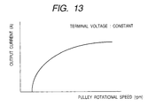
- Fig. 12 is a section view showing the configuration of a usual conventional automotive alternator, and Fig. 13 is an output characteristic diagram of the automotive alternator.
- 1 denotes a stator core which is formed into a cylindrical shape, and which has a poly-phase stator winding 2
- 3 and 4 denote front and rear brackets which hold the stator core 1
- 5 denotes a claw-pole type rotor core which is disposed within the inner diameter of the stator core 1 with forming an air gap therebetween, which has a field winding 6, and which is fixed to a rotation shaft 7
- 8a and 8b denote bearings which are disposed respectively on the front and rear brackets 3 and 4 to rotatably support the rotation shaft 7
- 9 denotes a pulley which is disposed on one end of the rotation shaft 7 on the side of the front bracket 3, and which is driven by an internal combustion engine (not shown)
- 10 denotes a slip ring which is fixed to the rotation shaft 7 to supply a field current to the field
- the field current is supplied to the field winding 6 via the brushes 12 and the slip ring 10, and the pulley 9 is driven by the internal combustion engine which is not shown. Then, AC power is generated in the poly-phase stator winding 2.
- the AC power is rectified by a full-wave rectifier which is incorporated into the alternator, and which is not shown, and then used for charging a battery mounted on a vehicle and supplied to loads.
- a voltage control device which is not shown is incorporated into the alternator.
- the voltage control device turns on and off the field current to hold the output voltage to a predetermined value.
- the alternator has characteristics in which, in the case where the terminal voltage is held to the predetermined value, for example, 14 V, as shown in Fig. 3, the output voltage rises when the generated voltage exceeds a predetermined voltage, and is increased as the rotational speed is made higher, to be saturated in the high speed range.
- an automotive alternator is requested to have output characteristics in which, even in the low speed range of an internal combustion engine, i.e., the idling range, the output is sufficient for supplying electric power to loads and charging a battery.
- the output current in such a low speed range it may be first contemplated to increase the size, particularly, the outer diameter of the alternator, or the pulley ratio with respect to the engine so as to make the rotational speed higher.
- an automotive alternator which is to be mounted in an engine compartment of a vehicle must be miniaturized and lightened. Therefore, it is very difficult to increase the size.
- the increase of the pulley ratio causes belt slip.
- the diameter of a pulley on the side of the crankshaft of the engine must be increased.
- the diameters of pulleys for various belt-driven auxiliary devices must be increased, thereby causing the internal combustion engine to be enlarged.
- the invention has been conducted in order to solve this problem. It is an object of the invention to provide an automotive alternator in which the output current in, particularly, the low rotational speed range including the idling range of an internal combustion engine can be increased without enlarging the outer diameter of the alternator, and the mechanical reliability is not impaired by the increase.
- the automotive alternator of the invention comprises: a stator core having a stator winding; front and rear brackets which hold the stator core from both sides; a rotor core which is attached to a rotation shaft that is rotatably mounted on the brackets, and which has a field winding; a one-way clutch which has a driving member and a driven member, the driven member being fixed to the rotation shaft; an overdrive planetary gear mechanism which has a sun gear, a planet gear, and an outer ring gear, the sun gear being fixed to the rotation shaft, one end of a support shaft of the planet gear being fixed to the driving member of the one-way clutch, the outer ring gear being rotatably supported; an input shaft to which another end of the support shaft of the planet gear of the overdrive planetary gear mechanism is fixed, and which receives a driving force from an internal combustion engine; and an electromagnetic brake which operates in response to energization to block rotation of the outer ring gear of the overdrive planetary gear mechanism.
- the alternator has a housing which is attached to the front bracket, and which covers an axial end portion of the rotation shaft, one end of the input shaft is supported by a bearing disposed on the housing, and another end of the input shaft is supported by the rotation shaft via the support shaft of the planet gear and the one-way clutch.
- a bearing is disposed on an outer diameter of the driving member of the one-way clutch, one end of a cylindrical member having the outer ring gear of the overdrive planetary gear mechanism is supported by the bearing, and another end of the cylindrical member is supported by the bearing disposed on the housing.
- the automotive alternator of the invention comprises: stator core having a stator winding; front and rear brackets which hold the stator core from both sides; a rotor core which is attached to a rotation shaft that is rotatably mounted on the brackets, and which has a field winding; an over drive planetary gear mechanism which has a sun gear, a planet gear, and an outer ring gear, the sun gear being fixed to the rotation shaft, one end of a support shaft of the planet gear being fixed to the driving member of the one-way clutch, the outer ring gear being rotatably supported; an input shaft to which the support shaft of the planet gear of the overdrive planetary gear mechanism is fixed, and which receives a driving force from an internal combustion engine; a one-way clutch which has a driving member and a driven member, the driving member being fixed to the input shaft, the driven member being coupled with a member having the outer ring gear of the overdrive planetary gear mechanism; and an electromagnetic brake which operates in response to energization to block rotation of the outer ring
- the alternator has a housing which is attached to the front bracket, and which covers an axial end portion of the rotation shaft, one end of the input shaft is supported by a bearing disposed on the housing, via the one-way clutch, the alternator further has a support member which is elongated from another end of the input shaft, and the support member is supported by a bearing disposed on the front bracket.
- the alternator has a housing which is attached to the front bracket, and which covers an axial end portion of the rotation shaft, one end of the input shaft is supported by a bearing disposed on the housing, via the one-way clutch, the alternator further has a support member which is elongated from another end of the input shaft, and the support member is supported by a bearing disposed on the rotation shaft.
- the automotive alternator of the invention comprises: a stator core having a stator winding; front and rear brackets which hold the stator core from both sides; a rotor core which is attached to a rotation shaft that is rotatably mounted on the brackets, and which has a field winding; a one-way clutch which has a driving member and a driven member, the driven member being fixed to the rotation shaft, the driving member being integrated with an input shaft driven by an internal combustion engine; an overdrive planetary gear mechanism which has a sun gear, a planet gear, and an outer ring gear, the sun gear being fixed to the rotation shaft, a support shaft of the planet gear being fixed to the driving member which is integrated with the input shaft, the outer ring gear being rotatably supported; and an electromagnetic brake which operates in response to energization to block rotation of the outer ring gear of the overdrive planetary gear mechanism.
- one end portion of a member having the outer ring gear is supported by the rotation shaft via a bearing, and another end of the member is supported via a bearing by an outer diameter of the driving member which is integrated with the input shaft.
- the alternator has a housing which is attached to the front bracket, and which covers an axial end portion of the rotation shaft, and the driving member of the one-way clutch which is integrated with the input shaft is supported by a bearing disposed on the housing.
- the driving member of the one-way clutch is attached to the input shaft via an elastic member.
- the input shaft which is driven by the internal combustion engine is configured to be separable from the driving member of the one-way clutch.
- the sun gear of the overdrive planetary gear mechanism which is fixed to the rotation shaft, and the driven member of the one-way clutch are integrally formed.
- the sun gear of the overdrive planetary gear mechanism which is fixed to the rotation shaft, and the driven member of the one-way clutch are separably formed.
- bearings which rotatably support a member having the outer ring gear are disposed respectively in two places in an axial direction, and at least one of the bearings bears radial and axial loads.
- the electromagnetic brake has: an exciting coil which magnetizes a magnetic path; and a moving element which is attracted by magnetization of the magnetic path to block rotation of the outer ring gear of the overdrive planetary gear mechanism, the electromagnetic brake is accommodated in the housing, and guide grooves which mutually engage with each other are formed in an inner face of the housing, and an outer face of the moving element.
- the member having the outer ring gear is formed into a U-like section shape having a bottom face and two side faces, the bottom face is a face abutting against the moving element of the electromagnetic brake, the two side faces surround inner and outer peripheries of the electromagnetic brake, and a gap between inner faces of the two side faces and an outer face of the magnetic path is larger as moving toward an opening of the U-like section shape.
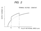
- Fig. 1 is a section view of an automotive alternator of Embodiment 1 of the invention, and Fig. 2 shows output characteristics of the automotive alternator.
- Fig. 1 denotes a stator core which is formed into a cylindrical shape, and which has a poly-phase stator winding
- 3 and 4 denote front and rear brackets which hold the stator core 1 from both the sides
- 5 denotes a claw-pole type rotor core which is disposed within the inner diameter of the stator core 1 with forming an air gap therebetween, which has a field winding 6, and which is fixed to a rotation shaft 7
- 8a and 8b denote bearings which are disposed respectively on the front and rear brackets 3 and 4 to rotatably support the rotation shaft 7,
- 10 denotes a slip ring which is fixed to the rotation shaft 7 to supply a field current to the field winding 6, and 11 denotes a brush holder which is attached to the rear bracket 4, and which has brushes 12 that are in sliding contact with the slip ring 10.
- the reference numeral 13 denotes an one-way clutch which has a driven member 14 attached to the rotation shaft 7, a torque transmitting member 15, and a driving member 16, 19 denotes an input shaft which is rotatably supported by a housing 18, and which at one end has a pulley 9 driven by an internal combustion engine (not shown), and 17 denotes an overdrive planetary gear mechanism having: a planet gear 21 which is attached to the input shaft 19 through a support shaft 20; a sun gear 22 which is disposed on one end of the rotation shaft 7; and an outer ring gear 24 which is disposed on the inner face of a cylindrical member 23 that is rotatably disposed.
- the support shaft 20 of the overdrive planetary gear mechanism 17 is coupled and fixed also to the driving member 16 of the one-way clutch 13.
- Aholding member 25 is disposed on the input shaft 19 and coupled to the driving member 16 of the one-way clutch 13, so that one end of the input shaft 19 is supported by the driving member 16 via the support shaft 20 and the holding member 25.
- the planet gear 21 is held between the driving member 16 and the input shaft 19.
- the reference numeral 26 denotes an electromagnetic brake which has a magnetic path 27, an exciting coil 28, and a moving element 29.
- the cylindrical member 23 which has the outer ring gear 24 of the overdrive planetary gear mechanism 17 is elongated so as to be interposed between the magnetic path 27 and the moving element 29.
- the cylindrical member 23 is further elongated into a U-like shape so as to surround the inner and outer peripheries of the magnetic path 27.
- the moving element 29 is attached to the front bracket 3 via a spring 30, and attracted toward the magnetic path 27 against the elasticity of the spring 30 in response to energization of the exciting coil 28, to be sucked to a brake surface 31 of the cylindrical member 23, thereby blocking rotation of the member.
- the reference numeral 32 denotes a bearing which is disposed on the housing 18 to rotatably support one end portion of the input shaft 19, 33 and 34 denote bearings which rotatably support the driving member 16 of the one-way clutch 13 with respect to the driven member 14 and the front bracket 3, and 35 and 36 denote bearings which rotatably support the cylindrical member 23 of the overdrive planetary gear mechanism 17 with respect to the housing 18 and the front bracket 3.
- the torque transmitting member 15 is in a free state, and hence transmission of rotation is not conducted between the driving member 16 of the one-way clutch 13 coupled with the input shaft 19 and the support shaft 20, and the driven member 14.
- the rotation shaft 7 and the rotator core 5 fixed thereto are rotated with being overdriven by a degree corresponding to the speed-increasing ratio of the overdrive planetary gear mechanism 17 with respect to the pulley 9.
- the electromagnetic brake 26 when the rotational speed of the pulley 9 is N1, the electromagnetic brake 26 is turned on, and, when the rotational speed is N2, the electromagnetic brake is turned off. In this case, when the rotational speed of the pulley is between N1 and N2, the rotational speed of the rotation shaft 7 is increased, so that the output current can be increased as shown in the figure.
- the electromagnetic brake 26 is turned off in the high speed range, the output in the low speed range in which the output is usually required to be increased can be attained by increasing the number of revolutions of the alternator.
- the one end of the input shaft 19 is supported by the bearing 32 and the other end is coupled to the driving member 16 of the one-way clutch 13 via the support shaft 20 and the holding member 25, the other end is supported by the bearing 34, and the rigidity of the input shaft 19 can be enhanced, so that it is possible to prevent an offset load from being applied to various portions of the overdrive planetary gear mechanism 17. Therefore, an overdrive mechanism of high reliability can be obtained.
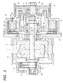
- Fig. 3 is a section view of an automotive alternator of Embodiment 2 of the invention.
- the automotive alternator of the embodiment is configured by modifying the automotive alternator of Embodiment 1 in the following manner.
- a bearing 37 is disposed between the outer diameter of the driving member 16 of the one-way clutch 13 and the cylindrical member 23 having the outer ring gear 24 of the overdrive planetary gear mechanism 17, thereby allowing one end portion of the outer ring gear 24 of the overdrive planetary gear mechanism 17 to be supported by the rotation shaft 7 via the one-way clutch 13.
- the bearing supporting the one-way clutch 13 can be used also as the bearing supporting the outer ring gear 24, and hence the number of parts can be reduced.
- Fig. 4 is a section view of an automotive alternator of Embodiment 3 of the invention.
- the automotive alternator of the embodiment is configured by modifying the automotive alternator of Embodiment 1 in the following manner.
- a one-way clutch 13a having a driven member 14a, the torque transmitting member 15, and a driving member 16a is attached to the outer periphery of the input shaft 19, and the driven member 14a is configured integrally with the cylindrical member 23 having the outer ring gear 24 of the overdrive planetary gear mechanism 17.
- the driving member 16a is fixed to the input shaft 19 through fixing means such as a key 38, a bearing 39 is disposed between the outer diameter of the driven member 14a and the housing 18 to support the one end of the input shaft 19, and the other end of the input shaft 19 is supported by the front bracket 3 via a bearing 40.
- the sun gear 22 of the overdrive planetary gear mechanism 17 is fixed to the rotation shaft 7, and the support shaft 20 of the planet gear 21 is fixed to the input shaft 19.
- the outer ring gear 24 is driven by the planet gear 21 at an angular velocity which is higher than that of the support shaft 20. Because of the coupling with the one-way clutch 13a, the outer ring gear is enabled to be rotated only at the same rotational speed as the input shaft 19. Therefore, the overdrive planetary gear mechanism 17 becomes stationary, and the rotation shaft 7 is rotated at the same rotational speed as that of the pulley 9.
- Fig. 5 is a section view of ah automotive alternator of Embodiment 4 of the invention.
- the automotive alternator of the embodiment is configured by modifying the automotive alternator of Embodiment 3 in the following manner.
- a socket 19a is disposed in a large diameter portion of the input shaft 19, and a support member 41 having a spigot 41a is fitted to the bearing 40 attached to the front bracket 3.
- the socket 19a of the input shaft 19, and the spigot 41a of the support member 41 are fitted to each other and then fixed by a screw 42, so that the support member 41 is configured as an elongated portion of the input shaft 19, thereby allowing both the ends of the input shaft 19 to be supported by the bearings 39 and 40.
- the rigidity of the input shaft 19 is ensured, and assembly can be performed in the procedure wherein the support member 41 is mounted onto the front bracket 3 and the planet gear 21 and the input shaft 19 are then attached to the support member 41. Therefore, the assembling property can be improved.
- Fig. 6 is a section view of an automotive alternator of Embodiment 5 of the invention.
- the automotive alternator of the embodiment is configured by modifying the automotive alternator of Embodiment 3 in the following manner.
- Abox-like part 19c which has an opening 19b in a radial direction is disposed in the end portion of the input shaft 19 opposite to the side having the pulley 9.
- the one end portion of the input shaft 19 is supported by the rotation shaft 7 via the tip end of the box-like part 19c and a bearing 43.
- the planet gear 21 is attached to a portion corresponding to the opening 19b. According to this configuration, the rigidity of the input shaft 19 is improved. Therefore, partial wear of the gears of the overdrive planetary gear mechanism 17 can be reduced, and the diameter of the bearing 43 itself can be reduced.
- Fig. 7 is a section view of an automotive alternator of Embodiment 6 of the invention.
- the automotive alternator of the embodiment is configured by modifying the automotive alternator of Embodiment 1 in the following manner.
- the pulley 9 which is driven by an internal combustion engine (not shown) is configured integrally with a driving member 16b of a one-way clutch 13b which serves also as the input shaft, and attached to the one end portion of the rotation shaft 7 via the torque transmitting member 15 and a driven member 14b.
- the planet gear 21 of the overdrive planetary gear mechanism 17 is attached to the driving member 16b by means of the support shaft 20.
- the sun gear 22 of the overdrive planetary gear mechanism 17 is disposed on the rotation shaft 7.
- the outer ring gear 24 is disposed on the cylindrical member 23 which is supported by the bearing 35 disposed on the front bracket 3, and a bearing 44 disposed on the outer diameter of the driving member 16b of the one-way clutch 13b.
- the brake surface 31 of the cylindrical member 23 is interposed between the magnetic path 27 and the moving element 29 of the electromagnetic brake 26.
- the pulley 9 is configured integrally with the driving member 16b of the one-way clutch 13b, moreover, the configurations of both the one-way clutch 13b and the overdrive planetary gear mechanism 17 can be simplified, and the number of parts of the bearings can be reduced.
- the pulley 9 and the driving member 16b of the one-way clutch 13b are integrally configured. Alternatively, they may be separately configured so that the driving member 16b can be first attached and the pulley can be then attached. In the alternative, the assembling property can be improved, and the interchangeability of pulleys of different diameters and the driving member 16b can be attained.
- the sun gear 22 of the overdrive planetary gear mechanism 17 which is attached to the rotation shaft 7, and the driven member 14b of the one-way clutch 13b which is similarly attached to the rotation shaft 7 are integrally configured, the number of parts can be reduced. When they are separately configured, the assembling property can be improved.
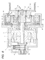
- Fig. 8 is a section view of an automotive alternator of Embodiment 7 of the invention.
- the automotive alternator of the embodiment is configured by modifying the automotive alternator of Embodiment 6 in the following manner.
- the one end portion of the cylindrical member 23 having the outer ring gear 24 is supported by the rotation shaft 7 via a bearing 45, and the other end is supported by the outer diameter of the driving member 16b of the one-way clutch 13b via the bearing 44.
- the eccentricity of the outer ring gear 24 with respect to the rotation shaft 7 is reduced, and also the rigidity of the cylindrical member 23 is attained, so that partial wear and damage of the gears of the overdrive planetary gear mechanism 17 can be reduced.
- Fig. 9 is a section view of an automotive alternator of Embodiment 8 of the invention.
- the automotive alternator of the embodiment is configured by modifying the automotive alternator of Embodiment 6 in the following manner.
- the pulley 9 which is driven by an internal combustion engine (not shown) is configured integrally with the driving member 16b of the one-way clutch 13b which serves also as the input shaft, and the outer diameter of the integral is supported by a bearing 46 disposed on the housing 18.
- the pulley 9, and hence the driving member 16b serving also as the input shaft receives a large moment load due to tension of a belt which is not shown.
- Fig. 10 is a section view of an automotive alternator of Embodiment 9 of the invention.
- the automotive alternator of the embodiment is configured by modifying the automotive alternator of Embodiment 6 in the following manner.
- An elastic member 47 such as a rubber damper is interposed between the driving member 16b of the one-way clutch 13b which is configured integrally with the pulley 9, and a member 15a engaged with the torque transmitting member 15 which transmits the power.
- a torque ripple due to torque variation of the internal combustion engine is applied to the pulley 9 which is driven by the internal combustion engine, and the driving member 16b.
- the torque ripple causes the torque transmitting member 15 to repeat coupling and separation, and metal fatigue occurs in the coupling face.
- torque ripple is absorbed, so that the life period of the one-way clutch 13b can be prolonged.
- the place where the elastic member 47 is interposed is not particularly restricted as far as the place exists between the pulley 9 and the coupling face of the torque transmitting member 15.
- the pulley 9 and the driving member 16b may be separated from each other and the elastic member may be interposed between them.
- Fig. 11 is a section view of an automotive alternator of Embodiment 10 of the invention.
- the automotive alternator of the embodiment is configured by modifying the automotive alternators of Embodiments 1 to 9 in the following manner.
- Concave and convex guides 18a are axially disposed in the inner face of the housing 18 which accommodates the electromagnetic brake 26.
- Guide grooves 29a which are to be engaged with the guides 18a of the inner face of the housing 18 are disposed in the outer face of the moving element 29 of the electromagnetic brake 26. According to this configuration, during operation of the electromagnetic brake 26, the moving element 29 can smoothly move, and the guides and the guide grooves can be used for positioning in assembling.
- the overdrive planetary gear mechanism, the electromagnetic brake which turns on and off the overdrive function of the overdrive planetary gear mechanism, and the one-way clutch which causes slippage between the input shaft and the rotation shaft to occur during the overdrive function are disposed, and the speed of the rotor can be increased in the low rotational speed range including the idling range of an internal combustion engine . Therefore, the output in the low rotational speed range can be increased without enlarging the outer diameter of the alternator.
- both the ends of the input shaft for driving the overdrive planetary gear mechanism are supported by using the support shaft of the planet gear and the holding member.
- the bearing for the one-way clutch is used also as the bearing for the overdrive planetary gear mechanism, and hence the number of parts can be reduced.
- the configuration of the fourth aspect of the invention it is possible to obtain an automotive alternator which, although the configuration is different from that of the first aspect of the invention, can attain the same effects as those of the first aspect of the invention, and in which the number of parts of the bearings can be reduced.
- the holding member which is supported by the bearing is attached to the input shaft, and hence it is possible to prevent an offset load from being applied to the overdrive planetary gear mechanism and the one-way clutch, without sacrifice of the assembling property.
- the one end of the input shaft is supported by the rotation shaft of the alternator. Therefore, the configuration has high rigidity, and partial wear and the like of the gears of the overdrive planetary gear mechanism can be reduced.
- the input shaft and the driving member of the one-way clutch are integrally configured, the support shaft of the planet gear is attached to the driving member, and the driven member of the one-way clutch is attached to the rotation shaft of the alternator. Therefore, it is possible to attain the same effects as those of the first aspect of the invention while the number of parts is reduced.
- the one end portion of the member having the outer ring gear of the overdrive planetary gear mechanism is supported by the rotation shaft of the alternator, and hence the eccentricity with respect to the rotation shaft is reduced, so that partial wear and damage of the gears of the overdrive planetary gear mechanism can be reduced.
- the outer diameter of the driving member which is configured integrally with the input shaft is supported by the bearing disposed on the housing. Therefore, excellent resistance against the bending moment applied to the pulley is exerted, and it is possible to prevent partial wear and damage of the gears of the overdrive planetary gear mechanism from occurring.
- the elastic member is interposed between the driving member of the one-way clutch and the input shaft, fatigue resistance against a torque ripple is improved.
- the input shaft and the driving member of the one-way clutch are configured so as to be separable from eachother. Therefore, the assembling property can be improved, and the interchangeability of the driving member with respect to input shafts respectively having pulleys of different diameters can be attained.
- the sun gear of the overdrive planetary gear mechanism, and the driven member of the one-way clutch are integrally formed, and hence the assembling property is excellent.
- the sun gear of the overdrive planetary gear mechanism, and the driven member of the one-way clutch are separately configured, and hence the assembling property is excellent.
- one of the bearings which support the member having the outer ring gear is configure so as to bear radial and axial loads. Even when a load in the thrust direction is applied during operation of the electromagnetic brake, therefore, the bearing can bear the load.
- guide grooves which mutually engage with each other are formed in the inner face of the housing of the electromagnetic brake, and the outer face of the moving element. Therefore, during operation of the electromagnetic brake, the moving element can smoothly move, and the guide grooves can be used for positioning in assembling.
- the gap between the magnetic path of the electromagnetic brake, and the member which has the outer ring gear, and which is formed into a U-like section shape so as to surround the magnetic path is set to be larger as moving toward the opening of the U-like section shape. Even when the member having the outer ring gear is tilted during operation of the electromagnetic brake, therefore, mutual interference can be prevented from occurring. In this way, it is possible to obtain an excellent automotive alternator.
Landscapes
- Engineering & Computer Science (AREA)
- General Engineering & Computer Science (AREA)
- Mechanical Engineering (AREA)
- Power Engineering (AREA)
- Connection Of Motors, Electrical Generators, Mechanical Devices, And The Like (AREA)
- Synchronous Machinery (AREA)
- Motor Or Generator Frames (AREA)
Abstract
Description
Claims (16)
- An automotive alternator comprising:a stator core having a stator winding;front and rear brackets which hold said stator core from both sides;a rotor core which is attached to a rotation shaft that is rotatably mounted on said brackets, and has a field winding;a one-way clutch which has a driving member and a driven member, said driven member being fixed to said rotation shaft;an overdrive planetary gear mechanism which has a sun gear, a planet gear, and an outer ring gear, said sun gear being fixed to said rotation shaft, one end of a support shaft of said planet gear being fixed to said driving member of said one-way clutch, said outer ring gear being rotatably supported;an input shaft to which another end of said support shaft of said planet gear of said overdrive planetary gear mechanism is fixed, and which receives a driving force from an internal combustion engine; andan electromagnetic brake which operates in response to energization to block rotation of said outer ring gear of said overdrive planetary gear mechanism.
- An automotive alternator according to claim 1, wherein said alternator has a housing which is attached to said front bracket, and which covers an axial end portion of said rotation shaft, one end of said input shaft is supported by a bearing disposed on said housing, and another end of said input shaft is supported by said rotation shaft via said support shaft of said planet gear and said one-way clutch.
- An automotive alternator according to claim 1 or 2, wherein a bearing is disposed on an outer diameter of said driving member of said one-way clutch, one end of a cylindrical member having said outer ring gear of said overdrive planetary gear mechanism is supported by said bearing, and another end of said cylindrical member is supported by said bearing disposed on said housing.
- An automotive alternator comprising:a stator core having a stator winding;front and rear brackets which hold said stator core from both sides;a rotor core which is attached to a rotation shaft that is rotatably mounted on said brackets and which has a field winding;an overdrive planetary gear mechanism which has a sun gear, a planet gear, and an outer ring gear, said sun gear being fixed to said rotation shaft, one end of a support shaft of said planet gear being fixed to said driving member of said one-way clutch, said outer ring gear being rotatably supported;an input shaft to which said support shaft of said planet gear of said overdrive planetary gear mechanism is fixed, and which receives a driving force from an internal combustion enginea one-way clutch which has a driving member and a driven member, said driving member being fixed to said input shaft, said driven member being coupled with a member having said outer ring gear of said overdrive planetary gear mechanism; andan electromagnetic brake which operates in response to energization to block rotation of said outer ring gear of said overdrive planetary gear mechanism.
- An automotive alternator according to claim 4, wherein said alternator has a housing which is attached to said front bracket, and covers an axial end portion of said rotation shaft, one end of said input shaft is supported by a bearing disposed on said housing, via said one-way clutch, said alternator further has a support member which is elongated from another end of said input shaft, and said support member is supported by a bearing disposed on said front bracket.
- An automotive alternator according to claim 4 or 5, wherein said alternator has a housing which is attached to said front bracket, and covers an axial end portion of said rotation shaft, one end of said input shaft is supported by a bearing disposed on said housing, via said one-way clutch, said alternator further has a support member which is elongated from another end of said input shaft, and said support member is supported by a bearing disposed on said rotation shaft.
- An automotive alternator comprising:a stator core having a stator winding;front and rear brackets which hold said stator core from both sides;a rotor core which is attached to a rotation shaft that is rotatably mounted on said brackets, and has afield winding;a one-way clutch which has a driving member and a driven member, said driven member being fixed to said rotation shaft, said driving member being integrated with an input shaft driven by an internal combustion engine;an overdrive planetary gear mechanism which has a sun gear, a planet gear, and an outer ring gear, said sun gear being fixed to said rotation shaft, a support shaft of said planet gear being fixed to said driving member which is integrated with said input shaft, said outer ring gear being rotatably supported; andan electromagnetic brake which operates in response to energization to block rotation of said outer ring gear of said overdrive planetary gear mechanism.
- An automotive alternator according to claim 7, wherein one end portion of a member having said outer ring gear is supported by said rotation shaft via a bearing, and another end of said member is supported via a bearing by an outer diameter of said driving member which is integrated with said input shaft.
- An automotive alternator according to claim 7 or 8, wherein said alternator has a housing which is attached to said front bracket, and covers an axial end portion of said rotation shaft, and said driving member of said one-way clutch which is integrated with said input shaft is supported by a bearing disposed on said housing.
- An automotive alternator according to any one of the preceding claims, wherein said driving member of said one-way clutch is attached to said input shaft via an elastic member.
- An automotive alternator according to any one of the preceding claims, wherein said input shaft which is driven by said internal combustion engine is configured to be separable from said driving member of said one-way clutch.
- An automotive alternator according to any one of the preceding claims, wherein said sun gear of said overdrive planetary gear mechanism which is fixed to said rotation shaft, and said driven member of said one-way clutch are integrally formed.
- An automotive alternator according to any one of the preceding claims, wherein said sun gear of said overdrive planetary gear mechanism which is fixed to said rotation shaft, and said driven member of said one-way clutch are separably formed.
- An automotive alternator according to any one of the preceding claims, wherein bearings which rotatably support a member having said outer ring gear are disposed respectively in two places in an axial direction, and at least one of said bearings bears radial and axial loads.
- An automotive alternator according to any one of the preceding claims, wherein said electromagnetic brake has: an exciting coil which magnetizes a magnetic path; and a moving element which is attracted by magnetization of said magnetic path to block rotation of said outer ring gear of said overdrive planetary gear mechanism, said electromagnetic brake is accommodated in said housing, and guide grooves which mutually engage with each other are formed in an inner face of said housing, and an outer face of said moving element.
- An automotive alternator according to any one of the preceding claims, wherein said member having said outer ring gear is formed into a U-like section shape having a bottom face and two side faces, said bottom face is a face abutting against said moving element of said electromagnetic brake, said two side faces surround inner and outer peripheries of said electromagnetic brake, and a gap between inner faces of said two side faces and an outer face of said magnetic path is larger as moving toward an opening of said U-like section shape.
Applications Claiming Priority (2)
| Application Number | Priority Date | Filing Date | Title |
|---|---|---|---|
| JP2000257110 | 2000-08-28 | ||
| JP2000257110A JP3712926B2 (en) | 2000-08-28 | 2000-08-28 | Vehicle alternator |
Publications (3)
| Publication Number | Publication Date |
|---|---|
| EP1220423A2 true EP1220423A2 (en) | 2002-07-03 |
| EP1220423A3 EP1220423A3 (en) | 2004-09-08 |
| EP1220423B1 EP1220423B1 (en) | 2006-05-03 |
Family
ID=18745626
Family Applications (1)
| Application Number | Title | Priority Date | Filing Date |
|---|---|---|---|
| EP01119741A Expired - Lifetime EP1220423B1 (en) | 2000-08-28 | 2001-08-27 | Automotive alternator |
Country Status (4)
| Country | Link |
|---|---|
| US (1) | US6609992B2 (en) |
| EP (1) | EP1220423B1 (en) |
| JP (1) | JP3712926B2 (en) |
| DE (1) | DE60119271T2 (en) |
Cited By (5)
| Publication number | Priority date | Publication date | Assignee | Title |
|---|---|---|---|---|
| GB2450307A (en) * | 2006-12-09 | 2008-12-24 | Joseph Henry Hudson | Alternator with a planetary gear set |
| US20130008284A1 (en) * | 2010-03-09 | 2013-01-10 | Toyota Jidosha Kabushiki Kaisha | Hybrid drive system |
| US8905881B2 (en) | 2010-03-09 | 2014-12-09 | Aisin Aw Co., Ltd. | Hybrid drive system |
| CN105515144A (en) * | 2016-01-26 | 2016-04-20 | 张红中 | Vibration attenuation power generator for vehicle |
| CN109873531A (en) * | 2019-04-11 | 2019-06-11 | 尉立 | Variable speed ring adjustment device for wind power generation |
Families Citing this family (20)
| Publication number | Priority date | Publication date | Assignee | Title |
|---|---|---|---|---|
| JP3710696B2 (en) * | 2000-08-29 | 2005-10-26 | 三菱電機株式会社 | AC rotating electric machine for vehicles |
| JP3810345B2 (en) * | 2002-06-04 | 2006-08-16 | 三菱電機株式会社 | Transmission control device for vehicle |
| US7316628B2 (en) * | 2004-01-13 | 2008-01-08 | The Gates Corporation Ip Law Dept. | Two speed transmission and belt drive system |
| US7798928B2 (en) * | 2004-03-24 | 2010-09-21 | The Gates Corporation | Dual ratio belt drive system |
| GB0412278D0 (en) * | 2004-06-02 | 2004-07-07 | Drivetec Uk Ltd | Drive pulleys |
| GB0427028D0 (en) * | 2004-12-09 | 2005-01-12 | Cambridge Consultants | Dry powder inhalers |
| FR2882699B1 (en) * | 2005-03-01 | 2008-10-31 | Peugeot Citroen Automobiles Sa | METHOD OF TAKING A VEHICLE UP AND DOWN AND LOADING |
| FR2890609B1 (en) * | 2005-09-12 | 2007-10-19 | Valeo Equip Electr Moteur | SYSTEM FOR ELECTRICALLY DRIVING EQUIPMENT ASSOCIATED WITH A THERMAL MOTOR |
| US20080096713A1 (en) * | 2006-10-10 | 2008-04-24 | Beson Thomas W | Overdrive and underdrive power converting modulators, and methods |
| US7713157B2 (en) * | 2007-07-11 | 2010-05-11 | Eaton Corporation | Planetary gear controlled alternator |
| US8152685B2 (en) * | 2009-02-13 | 2012-04-10 | Garmin International, Inc. | Planetary drive servo actuator |
| JP5477113B2 (en) * | 2010-03-31 | 2014-04-23 | 株式会社豊田自動織機 | Compressor with transmission |
| GB2481394A (en) * | 2010-06-21 | 2011-12-28 | Antonov Automotive Europ | Transmission unit for transmitting drive from an engine to an engine ancillary device |
| DE102011104144A1 (en) * | 2010-06-29 | 2011-12-29 | Schaeffler Technologies Gmbh & Co. Kg | Crankshaft pulley |
| DE102011010091A1 (en) * | 2011-02-01 | 2012-08-02 | Audi Ag | Motor vehicle with belt drive and planetary gear between internal combustion engine and electric machine |
| CN105720739A (en) * | 2016-04-14 | 2016-06-29 | 大同北方天力增压技术有限公司 | Magnetor |
| US11060582B2 (en) * | 2019-09-09 | 2021-07-13 | Chi Hua Fitness Co., Ltd. | Electric adjustable magnetic control damper |
| CN111059272B (en) * | 2019-12-31 | 2021-03-12 | 西南大学 | Center-drive adaptive electric drive system that prevents self-locking in reverse |
| CN111817458B (en) * | 2020-07-09 | 2022-09-06 | 河北科博锐程电力工程有限公司 | Power generator set |
| CN115395722B (en) * | 2022-10-31 | 2022-12-30 | 佛山市磁家有导科技有限公司 | Door and window locking and separating integrated motor system |
Family Cites Families (15)
| Publication number | Priority date | Publication date | Assignee | Title |
|---|---|---|---|---|
| US2327769A (en) * | 1941-04-02 | 1943-08-24 | Gen Motors Corp | Generator overdrive |
| US2998539A (en) * | 1957-12-16 | 1961-08-29 | Prec Mecanique Labinal | Devices for driving, especially alternators, at substantially constant speed from a variable speed shaft |
| DE1526560A1 (en) * | 1966-09-27 | 1970-04-02 | Daimler Benz Ag | Drive for ancillary units of an internal combustion engine, especially in motor vehicles |
| US4265135A (en) * | 1978-11-27 | 1981-05-05 | Borg-Warner Corporation | Automotive accessory drive |
| US4412460A (en) * | 1980-06-23 | 1983-11-01 | S.A. Automobiles Citroen | Two-speed couplings |
| US4862770A (en) * | 1987-07-13 | 1989-09-05 | Borg-Warner Automotive, Inc. | Two-speed alternator drive |
| JP2865808B2 (en) * | 1990-05-30 | 1999-03-08 | 株式会社日立製作所 | Starter |
| EP0548955B1 (en) * | 1991-12-27 | 1997-06-18 | Tochigifujisangyo Kabushiki Kaisha | Gear transmission apparatus |
| JPH08140308A (en) * | 1994-11-10 | 1996-05-31 | Mitsubishi Electric Corp | Vehicle charging generator |
| JP3710010B2 (en) | 1995-10-19 | 2005-10-26 | 株式会社デンソー | VEHICLE STARTING AND AUXILIARY DEVICE AND VEHICLE STARTING DEVICE |
| JP3095992B2 (en) * | 1996-02-14 | 2000-10-10 | 三菱電機株式会社 | Auxiliary drive |
| ATE248300T1 (en) * | 1997-05-07 | 2003-09-15 | Litens Automotive Inc | BELT DRIVE SYSTEM WITH GENERATOR CONNECTION ONE-WAY CLUTCH |
| US6234769B1 (en) * | 1997-07-09 | 2001-05-22 | Denso Corporation | Hybrid type compressor driven by engine and electric motor |
| JP3777751B2 (en) * | 1997-10-22 | 2006-05-24 | トヨタ自動車株式会社 | Engine starting and power generator |
| JP3547347B2 (en) * | 1999-09-20 | 2004-07-28 | 株式会社日立製作所 | Motor generator for vehicles |
-
2000
- 2000-08-28 JP JP2000257110A patent/JP3712926B2/en not_active Expired - Lifetime
-
2001
- 2001-08-27 DE DE60119271T patent/DE60119271T2/en not_active Expired - Lifetime
- 2001-08-27 EP EP01119741A patent/EP1220423B1/en not_active Expired - Lifetime
- 2001-08-28 US US09/939,791 patent/US6609992B2/en not_active Expired - Fee Related
Cited By (9)
| Publication number | Priority date | Publication date | Assignee | Title |
|---|---|---|---|---|
| GB2450307A (en) * | 2006-12-09 | 2008-12-24 | Joseph Henry Hudson | Alternator with a planetary gear set |
| US20130008284A1 (en) * | 2010-03-09 | 2013-01-10 | Toyota Jidosha Kabushiki Kaisha | Hybrid drive system |
| US8808128B2 (en) * | 2010-03-09 | 2014-08-19 | Aisin Aw Co., Ltd. | Hybrid drive system |
| US8870697B2 (en) | 2010-03-09 | 2014-10-28 | Aisin Aw Co., Ltd. | Power transmission device |
| US8882622B2 (en) | 2010-03-09 | 2014-11-11 | Aisin Aw Co., Ltd. | Hybrid drive system |
| US8905881B2 (en) | 2010-03-09 | 2014-12-09 | Aisin Aw Co., Ltd. | Hybrid drive system |
| CN105515144A (en) * | 2016-01-26 | 2016-04-20 | 张红中 | Vibration attenuation power generator for vehicle |
| CN109873531A (en) * | 2019-04-11 | 2019-06-11 | 尉立 | Variable speed ring adjustment device for wind power generation |
| CN109873531B (en) * | 2019-04-11 | 2024-04-05 | 泛在能源(山东)有限公司 | Speed-changing ring adjusting device for wind power generation |
Also Published As
| Publication number | Publication date |
|---|---|
| JP3712926B2 (en) | 2005-11-02 |
| DE60119271T2 (en) | 2007-04-12 |
| US6609992B2 (en) | 2003-08-26 |
| EP1220423A3 (en) | 2004-09-08 |
| US20020049112A1 (en) | 2002-04-25 |
| DE60119271D1 (en) | 2006-06-08 |
| EP1220423B1 (en) | 2006-05-03 |
| JP2002078287A (en) | 2002-03-15 |
Similar Documents
| Publication | Publication Date | Title |
|---|---|---|
| US6609992B2 (en) | Automotive alternator | |
| JP3268007B2 (en) | Meander belt drive and alternator assembly for automobiles | |
| JP4420826B2 (en) | 2-arm belt tensioner for belt drive | |
| US4870875A (en) | Driving device for auxiliary device | |
| JP3095992B2 (en) | Auxiliary drive | |
| RU2489618C1 (en) | Isolating disconnector | |
| RU2405952C2 (en) | Variable transmission ratio belt transmission system | |
| US8057334B2 (en) | Accessory drive tensioner assembly | |
| US6333577B1 (en) | Automotive AC dynamo-electric machine | |
| US20100259121A1 (en) | Power transmission device | |
| US5751070A (en) | Combined starter and generator apparatus | |
| US5959385A (en) | Rotary machine having starter for vehicle | |
| US6857984B2 (en) | Starter having thrust receiving member between motor shaft and output shaft | |
| JP3379884B2 (en) | Engine starter | |
| EP0795432A2 (en) | Method for mounting two auxiliary machines to automobile and power transmission device | |
| JPH11230012A (en) | Auxiliary drive using starter motor | |
| US20020025880A1 (en) | Automotive AC rotating machine | |
| KR101426569B1 (en) | Crankshaft clutch device for hybrid vehicles | |
| WO2005010392A1 (en) | Electromagnetic clutch | |
| JP3519061B2 (en) | Electric rotating machine for vehicles | |
| JP3570453B2 (en) | One-way clutch | |
| JP3544364B2 (en) | Belt transmission | |
| EP0781906A1 (en) | Apparatus for driving alternator of engine, and alternator for engine accessoires used therefor | |
| KR100359609B1 (en) | Generator assembly for internal-combustion engine | |
| KR100369023B1 (en) | An alternator of rotation control type |
Legal Events
| Date | Code | Title | Description |
|---|---|---|---|
| PUAI | Public reference made under article 153(3) epc to a published international application that has entered the european phase |
Free format text: ORIGINAL CODE: 0009012 |
|
| AK | Designated contracting states |
Kind code of ref document: A2 Designated state(s): AT BE CH CY DE DK ES FI FR GB GR IE IT LI LU MC NL PT SE TR |
|
| AX | Request for extension of the european patent |
Free format text: AL;LT;LV;MK;RO;SI |
|
| RIC1 | Information provided on ipc code assigned before grant |
Ipc: 7H 02K 7/102 B Ipc: 7F 16H 3/54 A Ipc: 7H 02K 7/116 B |
|
| PUAL | Search report despatched |
Free format text: ORIGINAL CODE: 0009013 |
|
| AK | Designated contracting states |
Kind code of ref document: A3 Designated state(s): AT BE CH CY DE DK ES FI FR GB GR IE IT LI LU MC NL PT SE TR |
|
| AX | Request for extension of the european patent |
Extension state: AL LT LV MK RO SI |
|
| 17P | Request for examination filed |
Effective date: 20050216 |
|
| 17Q | First examination report despatched |
Effective date: 20050324 |
|
| AKX | Designation fees paid |
Designated state(s): DE FR |
|
| GRAP | Despatch of communication of intention to grant a patent |
Free format text: ORIGINAL CODE: EPIDOSNIGR1 |
|
| GRAS | Grant fee paid |
Free format text: ORIGINAL CODE: EPIDOSNIGR3 |
|
| GRAA | (expected) grant |
Free format text: ORIGINAL CODE: 0009210 |
|
| AK | Designated contracting states |
Kind code of ref document: B1 Designated state(s): DE FR |
|
| RAP1 | Party data changed (applicant data changed or rights of an application transferred) |
Owner name: MITSUBISHI DENKI KABUSHIKI KAISHA |
|
| REF | Corresponds to: |
Ref document number: 60119271 Country of ref document: DE Date of ref document: 20060608 Kind code of ref document: P |
|
| ET | Fr: translation filed | ||
| PLBE | No opposition filed within time limit |
Free format text: ORIGINAL CODE: 0009261 |
|
| STAA | Information on the status of an ep patent application or granted ep patent |
Free format text: STATUS: NO OPPOSITION FILED WITHIN TIME LIMIT |
|
| 26N | No opposition filed |
Effective date: 20070206 |
|
| PGFP | Annual fee paid to national office [announced via postgrant information from national office to epo] |
Ref country code: DE Payment date: 20100825 Year of fee payment: 10 Ref country code: FR Payment date: 20100824 Year of fee payment: 10 |
|
| REG | Reference to a national code |
Ref country code: FR Ref legal event code: ST Effective date: 20120430 |
|
| REG | Reference to a national code |
Ref country code: DE Ref legal event code: R119 Ref document number: 60119271 Country of ref document: DE Effective date: 20120301 |
|
| PG25 | Lapsed in a contracting state [announced via postgrant information from national office to epo] |
Ref country code: FR Free format text: LAPSE BECAUSE OF NON-PAYMENT OF DUE FEES Effective date: 20110831 |
|
| PG25 | Lapsed in a contracting state [announced via postgrant information from national office to epo] |
Ref country code: DE Free format text: LAPSE BECAUSE OF NON-PAYMENT OF DUE FEES Effective date: 20120301 |