EP1220259A2 - Fast acting electrically powered operator for transfer switch and transfer switch incorporating same - Google Patents
Fast acting electrically powered operator for transfer switch and transfer switch incorporating same Download PDFInfo
- Publication number
- EP1220259A2 EP1220259A2 EP01131010A EP01131010A EP1220259A2 EP 1220259 A2 EP1220259 A2 EP 1220259A2 EP 01131010 A EP01131010 A EP 01131010A EP 01131010 A EP01131010 A EP 01131010A EP 1220259 A2 EP1220259 A2 EP 1220259A2
- Authority
- EP
- European Patent Office
- Prior art keywords
- handle
- solenoid
- yoke
- coupling
- electric power
- Prior art date
- Legal status (The legal status is an assumption and is not a legal conclusion. Google has not performed a legal analysis and makes no representation as to the accuracy of the status listed.)
- Granted
Links
Images



Classifications
-
- H—ELECTRICITY
- H01—ELECTRIC ELEMENTS
- H01H—ELECTRIC SWITCHES; RELAYS; SELECTORS; EMERGENCY PROTECTIVE DEVICES
- H01H71/00—Details of the protective switches or relays covered by groups H01H73/00 - H01H83/00
- H01H71/10—Operating or release mechanisms
- H01H71/66—Power reset mechanisms
- H01H71/68—Power reset mechanisms actuated by electromagnet
-
- H—ELECTRICITY
- H01—ELECTRIC ELEMENTS
- H01H—ELECTRIC SWITCHES; RELAYS; SELECTORS; EMERGENCY PROTECTIVE DEVICES
- H01H71/00—Details of the protective switches or relays covered by groups H01H73/00 - H01H83/00
- H01H71/10—Operating or release mechanisms
- H01H71/66—Power reset mechanisms
- H01H2071/665—Power reset mechanisms the reset mechanism operating directly on the normal manual operator, e.g. electromagnet pushes manual release lever back into "ON" position
-
- H—ELECTRICITY
- H01—ELECTRIC ELEMENTS
- H01H—ELECTRIC SWITCHES; RELAYS; SELECTORS; EMERGENCY PROTECTIVE DEVICES
- H01H2300/00—Orthogonal indexing scheme relating to electric switches, relays, selectors or emergency protective devices covered by H01H
- H01H2300/018—Application transfer; between utility and emergency power supply
Definitions
- This invention relates to switches for electric power distribution systems and, more particularly, to electrically powered operators for interlocking the operation of a pair of switches, such as those in a transfer switch.
- the operation of the two switches is coordinated, typically by a mechanical interlock, so that only one switch at a time can be turned ON.
- electric motors have been used to operate the interlocks on transfer switches. The motor powered interlocks operate relatively slowly so that there is a noticeable dead period between the time that one of the switches is turned OFF and the other is turned ON. It is desirable to minimize this dead period while assuring that the two switches are never both ON at the same time.
- United States Patent No. 4,553,115 describes a solenoid powered operator for a single, molded case circuit breaker. This device operates the circuit breaker handle rapidly each time the solenoid is energized. It would be desirable to be able to operate the pair of switches in a transfer switch at a similar rapid rate, thereby reducing the interval in which the load is unenergized.
- the invention is directed to a fast acting, electrically powered operator for a pair of electric power switches and to a transfer switch incorporating this operator.
- the switches of a transfer switch are mounted end to end with their handles oppositely reciprocable in a common plane between OFF and ON positions.
- the electrically powered operator comprises a solenoid, and a mechanical assembly coupling the solenoid to the handle of the first switch for reciprocating the handle between the ON and OFF positions on successive actuations of the solenoid.
- a coupling comprising an elongated member couples the handle of the second switch to the handle of the first switch for movement therewith to reciprocate the handle of the second switch between the OFF position and the ON position opposite to the ON position and OFF position of the handle of the first switch.
- the solenoid is a single action solenoid having an electromagnet and an armature movable relative to the electromagnet.
- the mechanical assembly includes a first drive member coupled to the electromagnet and a second drive member coupled to the armature.
- a latch mechanism reciprocates between a first latch position in which the first drive member is held fixed and the second drive member moves upon actuation of the single action solenoid, and a second latch position in which the second drive member is held fixed and the first drive member moves upon actuation of the single action solenoid.
- a first yoke engages the first handle to reciprocate the first handle between the ON and OFF positions on successive actuations of the single action solenoid through alternate engagement by one and then the other of the first and second drive members.
- the first yoke engages and toggles the toggle mechanism as the first handle reciprocates between the ON and OFF positions.
- the elongated member of the coupling is coupled to the first yoke.
- a second yoke connects the elongated member to the second handle.
- the coupling includes a guide mounted on the second switch guiding the reciprocal movement of the elongated member and maintaining the second yoke in engagement with the second handle.
- the mechanical assembly includes a frame mounted on the first switch and within which the first and second drive members reciprocate.
- the frame includes a guide in the form of a slot for guiding reciprocal movement of the elongated member and maintaining the elongated member in engagement with the first handle through the first yoke.
- the invention also embraces the fast acting, electrically powered operator for a pair of end mounted electric power switches.
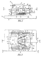
- FIG 1 illustrates a transfer switch 1 which incorporates a pair of electric power switches 3 and 5.
- These electric power switches 3 and 5 can be molded case switches, which are well known in the power distribution field. If overcurrent protection is desired, the switches 3 and 5 can be circuit breakers.
- the switches 3 and 5 have handles 7 and 9, respectively, which move rectilinearly between ON and OFF positions, as is well known.
- the two switches 3 and 5 are mounted end to end, such as on a panel board 11, with the handles 7 and 9 movable in a common plane.
- the switches 3 and 5 are oppositely oriented so that with the handles 7 and 9 turned in the same direction, one switch is ON and the other is OFF.
- the electrically powered operator 13 incorporates a single action solenoid 17 which includes an electromagnet 19 having a single electrical coil 21 wound on a magnetic core 23 and a generally T-shaped armature 25 that is movable with respect to and within the electromagnet 19.
- the solenoid 17 is coupled to the handle 7 of the switch 3 by a mechanical assembly 26.
- This mechanical assembly 26 includes a first drive member in the form or an electromagnet drive plate 27 that is secured to the electromagnet 19 and mounted for rectilinear movement along the axis of movement of the handle 7.
- the armature 25 is secured to a second drive member in the form of an armature drive plate 29 that is also disposed for rectilinear movement along the axis of movement of the handle 7 but on the opposite side of the handle from the electromagnet drive plate 27.
- the electromagnet drive plate 27 slides on a mounting plate or frame 31 and is contained by side flanges 33, end flanges 35 and top flanges 37 formed by the mounting plate 31.
- the electromagnet drive plate 27 has a flat base section 27a, upstanding side flanges 27b and horizontal terminal flanges 27c on which the electromagnetic is mounted. Offset end flanges 27d are aligned with the end flanges 35 on the mounting plate 31.
- the armature drive plate 29 slides on the mounting plate 31 and is contained by sides flanges 33, end flanges 35 and top flanges 37.
- the armature drive plate 29, as shown in Figure 9, has a flat base section 29a, a vertical flange 29b, a horizontal terminal flange 29c on which the armature is mounted and offset end flanges 29d aligned with end flanges 35 on the mounting plate 31.
- the mounting plate 31 is secured to the top of the molded housing 41 of the switch 3 by fasteners 43.
- the mounting plate 31 includes four rectangular latch slots 45 and a pair of latch pivot center apertures 47.
- the mounting plate 31 also includes, at the center of each side, an integrally formed, upstanding spring bracket 49 each having a pair of integrally formed, inwardly bent rigid ears 51 for engaging the ends of four helical compression springs 53.
- These helical compression springs 53 bear against offset end flanges 27d of the electromagnet drive plate 27 or the offset ends 29d of the armature drive plate 29, as seen in Figures 2-4, to bias the drive plates 27 and 29 to their limit positions.
- the mechanical assembly 26 incorporates a latch mechanism 55.
- this latch mechanism 55 includes a first yoke 57 which comprises a base 59 having a transverse slot 61 in a bottom face 63 that seats on an escutcheon 65 on the molded housing 41 of the switch 3 surrounding the handle 7.
- the yoke 57 has an upstanding collar 67 with a through aperture 69 in which the handle 7 is captured.
- the electromagnet drive plate 27 and the armature drive plate 29 bear against opposite sides of the yoke 57 to drive the handle 7 between the ON and OFF positions.
- Latch mechanism 55 also includes a pair of pivotable, bistable mechanical spring latches 71 configured to alternately engage and stop further movement of the electromagnet drive plate 27 and the armature drive plate 29.
- Each of the spring latches 71 includes a latch arm 73 and a helical tension spring 75 stretched between the ends of the latch arm 73.
- the latch arms 73 have stops 77 and 79 integrally formed at opposite ends that extend through the latch slots 45 in the mounting plate 31 and are configured to engage and stop the movement of the electromagnetic drive plate 27 and the armature drive plate 29, respectively.
- the latch arms 73 are mounted for pivotable movement beneath the mounting plate 31 by pivot rivets 81 engaging the latch pivot apertures 47.
- the yoke 57 includes, at the laterally outward ends of the base 59, latch camming surfaces 83 which engage and laterally deflect the tension springs 75 on the latch arms 73.
- the latch arms 73 have two stable positions. In the first stable position, shown in Figure 3, the latch arms 73 are rotated so that the stops 77 are in position to engage and limit the movement of the electromagnet drive plate 27. In the second stable position, the latch arms 73 are rotated to the positions, shown in Figure 6, where the stops 79 are rotated inward to form stops for and set the limit of travel of the armature drive plate 29.
- the bistable latch arms 73 rapidly transfer between the two stable positions by movement of the camming surfaces 83 on the base 59 of the yoke 57 from one side to the other of the pivot axes of the latch arms 73 as the yoke 57 is alternately driven by the drive plates 27 and 29.
- the electrically powered operator 13 further includes a coupling 85 which couples the handle 9 of the second electric power switch 5 to the handle 7 of the first switch 3.
- This coupling 85 includes an elongated member, such as the flat strap 87 which has a first opening 89 sized to engage the collar 67 on the first yoke 57.
- a second opening 91 in the strap 87 is positioned and sized to engage the collar 93 on a second yoke 95 which engages the second handle 9 on the second switch 5.
- This second yoke 95 also engages and slides along an escutcheon (not shown) on the molded housing 97 of the second switch 5.
- the same part can be used for the yoke 95 as the yoke 57 to reduce the parts count, although the camming surfaces 83 are not utilized on the second yoke 95.
- the flat strap 87 extends through a slot 99 in the flange 29b of the armature drive plate 29 which serves as a guide for the strap 87 and prevents it from lifting up off of the collar 67 on the yoke 57.
- a bracket 107 integrally formed on mounting plate 109 on the second switch 5 holds the strap 87 down and in engagement with the collar 93 of the second yoke 95.
- the operation of the transfer switch 1 is as follows:
- the solenoid 17 provides rapid operation of the transfer switch 1.
- the mechanical assembly 26 allows a single action solenoid to be used, as the latch mechanism alternately reverses the single motion of the solenoid for turning the switches OFF and ON.
Landscapes
- Physics & Mathematics (AREA)
- Electromagnetism (AREA)
- Breakers (AREA)
- Mechanical Control Devices (AREA)
- Push-Button Switches (AREA)
Abstract
Description
Claims (10)
- A transfer switch, comprising:first and second electric power switches having first and second operating handles, respectively, reciprocal in a common plane between ON and OFF positions, andan electrically powered operator comprising:a solenoid;a mechanical assembly coupling the solenoid to the first handle of the first electric power switch for reciprocating the first handle between the ON and OFF positions on successive actuations of the solenoid; anda coupling coupling the handle of the second electric power switch to the mechanical assembly for movement with the first handle to reciprocate the second handle between the OFF position and the ON position opposite to the OFF position and the ON position of the first handle.
- The transfer switch of Claim 1 wherein the first and second electric power switches are mounted end to end with the first and second operating handles oppositely reciprocal in a common plane between the ON and OFF positions, and the coupling comprises an elongated member coupling the handle of the second electric power switch to the mechanical assembly.
- The transfer switch of Claim 2 wherein the solenoid comprises a single action solenoid having an electromagnet and an armature movable relative to the electromagnet, the mechanical assembly comprises a first drive member coupled to the electromagnet, a second drive member coupled to the armature, a latch mechanism reciprocal between a first latch position in which the first drive member is held fixed and the second drive member moves upon actuation of the single action solenoid and a second latch position in which the second drive member is held fixed and a first drive member moves upon actuation of the single action solenoid and a first yoke engaging the first handle and reciprocating the first handle between the ON and OFF positions on successive actuations of the single action solenoid through alternate engagement by one and then the other of the first and second drive members, the first yoke engaging and toggling the latch mechanism as the first handle reciprocates between the ON and OFF positions, and the elongated member being coupled to the first yoke.
- The transfer switch of Claim 3 wherein the coupling includes a second yoke coupling the elongated member to the second operating handle.
- The transfer switch of Claim 4 wherein the coupling includes a guide mounted on the second electric power switch guiding reciprocation of the elongated member and maintaining the second yoke in engagement with the second operating handle.
- The transfer switch of Claim 5 wherein the mechanical assembly includes a frame mounted on the first electric power switch and in which the first drive member and second drive member slide, the frame including a guide guiding reciprocal movement of the elongated member and maintaining the elongated member in engagement with the first operating handle.
- The transfer switch of Claim 6 wherein the guide of the mechanical assembly comprises a slot in the frame through which the elongated member extends between the first yoke and the second yoke.
- An electrically powered operator for first and second power switches mounted end to end and having a first operating handle and a second operating handle, respectively, oppositely reciprocal in a common plane between ON and OFF positions, said operator comprising:a solenoid;a mechanical assembly coupling the solenoid to the first operating handle of the first electric power switch for reciprocating the first operating handle between the ON and OFF positions on successive actuations of the solenoid; anda coupling comprising an elongated member coupling the second operating handle of the second electric power switch to the mechanical assembly for movement with the first operating handle to reciprocate the second operating handle between the OFF position and the ON position opposite the ON position and the OFF position of the first operating handle.
- The electrically powered operator of Claim 8 wherein the solenoid is a single action solenoid having an electromagnet and an armature movable relative to the electromagnet, and the mechanical assembly comprises a first drive member coupled to the electromagnet and a second drive member coupled to the armature, a latch mechanism reciprocal between a first latch position in which the first drive member is held fixed and a second drive member moves upon actuation of the single action solenoid and a second latch position in which the second drive member is held fixed and the first drive member moves upon actuation of the single action solenoid, a first yoke engaging the first handle and reciprocating the first handle between the ON and OFF positions on successive actuations of the single action solenoid through alternate engagement of the first yoke by one and then the other of the first and second drive members, the first yoke engaging and toggling the latch mechanism as the first handle reciprocates between the ON and OFF positions, and the elongated member being coupled to the first yoke for movement with the first yoke.
- The electrically powered operator of Claim 9 wherein the coupling further includes a second yoke secured to the elongated member and engaging the second handle.
Applications Claiming Priority (2)
| Application Number | Priority Date | Filing Date | Title |
|---|---|---|---|
| US750572 | 1991-08-27 | ||
| US09/750,572 US6590481B2 (en) | 2000-12-28 | 2000-12-28 | Fast acting, electrically powered operator for transfer switch and transfer switch incorporating same |
Publications (3)
| Publication Number | Publication Date |
|---|---|
| EP1220259A2 true EP1220259A2 (en) | 2002-07-03 |
| EP1220259A3 EP1220259A3 (en) | 2004-03-17 |
| EP1220259B1 EP1220259B1 (en) | 2007-07-18 |
Family
ID=25018395
Family Applications (1)
| Application Number | Title | Priority Date | Filing Date |
|---|---|---|---|
| EP01131010A Expired - Lifetime EP1220259B1 (en) | 2000-12-28 | 2001-12-28 | Fast acting electrically powered operator for transfer switch and transfer switch incorporating same |
Country Status (5)
| Country | Link |
|---|---|
| US (1) | US6590481B2 (en) |
| EP (1) | EP1220259B1 (en) |
| BR (1) | BR0106591A (en) |
| CA (1) | CA2366086C (en) |
| DE (1) | DE60129406D1 (en) |
Cited By (2)
| Publication number | Priority date | Publication date | Assignee | Title |
|---|---|---|---|---|
| FR2928027A1 (en) * | 2008-02-25 | 2009-08-28 | Fuji Elec Fa Components & Sys | Remotely operating unit for circuit breaker, has coils selectively switched for performing specified operation such as running, stop and initial state resetting operations of lever while mobile unit is coupled to lever of circuit breaker |
| CN103594293B (en) * | 2009-09-29 | 2016-06-08 | 湖北盛佳电器设备有限公司 | There is the C type intelligent breaker of automatic switching-in function |
Families Citing this family (26)
| Publication number | Priority date | Publication date | Assignee | Title |
|---|---|---|---|---|
| US7053570B2 (en) * | 2003-12-01 | 2006-05-30 | Eaton Corporation | Control circuit for a dual directional direct current motor employing a single alternating current power source |
| US7777600B2 (en) | 2004-05-20 | 2010-08-17 | Powerpath Technologies Llc | Eddy current inductive drive electromechanical liner actuator and switching arrangement |
| US20060028069A1 (en) * | 2004-08-09 | 2006-02-09 | Loucks David G | Retrofit kit for converting a transfer switch to a switch for soft-load transfer, and soft-load power distribution system and method |
| TWM261629U (en) * | 2004-08-27 | 2005-04-11 | Tricore Corp | Improved return structure of core bar for electromagnetic valve |
| US7498923B2 (en) * | 2004-09-08 | 2009-03-03 | Iversen Arthur H | Fast acting, low cost, high power transfer switch |
| US7336003B2 (en) * | 2005-04-05 | 2008-02-26 | Eaton Corporation | Transfer switch and power system including the same |
| US20060244557A1 (en) * | 2005-05-02 | 2006-11-02 | Sorenson Richard W | Mountable remote actuated circuit breaker driver |
| USD562266S1 (en) * | 2005-12-30 | 2008-02-19 | Gen-Tran Corporation | Lockout device for a transfer switch |
| US7683780B2 (en) * | 2006-07-24 | 2010-03-23 | Thingmagic, Inc. | Methods and apparatus for RFID tag placement |
| US8081063B2 (en) | 2006-11-13 | 2011-12-20 | Trimble Navigation Limited | Systems and methods for Q value determination |
| US7569949B2 (en) | 2007-01-26 | 2009-08-04 | Eaton Corporation | Transfer switch with generator maintenance indicator |
| US20080179958A1 (en) * | 2007-01-26 | 2008-07-31 | Eaton Corporation | Automatic Transfer Switch With Monitor Mode and Method Employing the Same |
| US20080179967A1 (en) * | 2007-01-26 | 2008-07-31 | Eaton Corporation | Transfer Switch With Generator Runtime Counter |
| US7531919B2 (en) * | 2007-04-23 | 2009-05-12 | Eaton Corporation | Multiple generator loadcenter and method of distributing power from multiple generators |
| US7615888B2 (en) * | 2007-04-23 | 2009-11-10 | Eaton Corporation | Multiple generator loadcenter and method of distributing power from multiple generators |
| US8050001B2 (en) * | 2008-08-07 | 2011-11-01 | Crucs Holdings, Llc | Timed electrical outlet and a method of operation thereof |
| US8174148B2 (en) * | 2008-08-07 | 2012-05-08 | Crucs Holdings, Llc | Controllable electrical outlet and a method of operation thereof |
| US8138933B2 (en) * | 2008-11-05 | 2012-03-20 | Crucs Holdings, Llc | Systems, methods, and apparatus for automatically disabling appliances in response to a smoke detector |
| CN101807494B (en) * | 2009-09-29 | 2013-08-21 | 湖北盛佳电器设备有限公司 | Built-in type C intelligent circuit breaker with automatic closing function |
| US9583942B2 (en) * | 2011-04-20 | 2017-02-28 | Reliance Controls Corporation | Transfer switch for automatically switching between alternative energy source and utility grid |
| US9184014B2 (en) | 2013-02-01 | 2015-11-10 | General Electric Company | Electrical operator for circuit breaker and method thereof |
| US9330861B2 (en) | 2013-03-14 | 2016-05-03 | General Electric Company | Arc chute assembly for an automatic transfer switch system and methods of assembling the same |
| US10083809B2 (en) | 2016-04-21 | 2018-09-25 | Hartland Controls, Llc | Electrical power transfer switch |
| US9865416B2 (en) | 2016-04-21 | 2018-01-09 | Hartland Controls, Llc | Electrical power transfer switch |
| CN109494096B (en) * | 2018-12-30 | 2024-04-09 | 无锡双欢电气有限公司 | Mechanical interlocking operation device of switch cabinet |
| US11894207B2 (en) * | 2019-11-12 | 2024-02-06 | Eaton Intelligent Power Limited | Smart bus plug remote actuation, monitoring, and control |
Family Cites Families (9)
| Publication number | Priority date | Publication date | Assignee | Title |
|---|---|---|---|---|
| US3778633A (en) * | 1972-08-14 | 1973-12-11 | Gen Electric | Automatic electric power source transfer apparatus |
| US4167716A (en) | 1978-04-03 | 1979-09-11 | Gould Inc. | Controlled switching apparatus |
| US4553115A (en) | 1984-01-09 | 1985-11-12 | Westinghouse Electric Corp. | Molded case circuit breaker with single solenoid operator for rectilinear handle movement |
| FR2559616B1 (en) * | 1984-02-14 | 1986-05-30 | Merlin Gerin | AUXILIARY BLOCK FOR REMOTE CONTROL OF AN ELECTRIC CIRCUIT BREAKER |
| US4691180A (en) * | 1986-06-19 | 1987-09-01 | Westinghouse Electric Corp. | Circuit breaker with electrical disconnect means |
| US4804933A (en) | 1988-04-01 | 1989-02-14 | Brown Industrial Gas, Inc. | Automatic transfer switch |
| US5343179A (en) | 1993-01-29 | 1994-08-30 | Eaton Corporation | Miniaturized solenoid operated trip device |
| US5422453A (en) * | 1993-09-28 | 1995-06-06 | Eaton Corporation | Handle actuator for a circuit interrupter handle |
| US6096986A (en) * | 1999-09-08 | 2000-08-01 | Reliance Controls Corporation | Channel-type circuit breaker switch interlock |
-
2000
- 2000-12-28 US US09/750,572 patent/US6590481B2/en not_active Expired - Fee Related
-
2001
- 2001-12-21 CA CA2366086A patent/CA2366086C/en not_active Expired - Fee Related
- 2001-12-27 BR BR0106591-2A patent/BR0106591A/en not_active IP Right Cessation
- 2001-12-28 DE DE60129406T patent/DE60129406D1/en not_active Expired - Lifetime
- 2001-12-28 EP EP01131010A patent/EP1220259B1/en not_active Expired - Lifetime
Cited By (2)
| Publication number | Priority date | Publication date | Assignee | Title |
|---|---|---|---|---|
| FR2928027A1 (en) * | 2008-02-25 | 2009-08-28 | Fuji Elec Fa Components & Sys | Remotely operating unit for circuit breaker, has coils selectively switched for performing specified operation such as running, stop and initial state resetting operations of lever while mobile unit is coupled to lever of circuit breaker |
| CN103594293B (en) * | 2009-09-29 | 2016-06-08 | 湖北盛佳电器设备有限公司 | There is the C type intelligent breaker of automatic switching-in function |
Also Published As
| Publication number | Publication date |
|---|---|
| EP1220259A3 (en) | 2004-03-17 |
| DE60129406D1 (en) | 2007-08-30 |
| BR0106591A (en) | 2002-10-01 |
| US6590481B2 (en) | 2003-07-08 |
| EP1220259B1 (en) | 2007-07-18 |
| CA2366086C (en) | 2011-08-02 |
| CA2366086A1 (en) | 2002-06-28 |
| US20020093405A1 (en) | 2002-07-18 |
Similar Documents
| Publication | Publication Date | Title |
|---|---|---|
| CA2366086C (en) | Fast acting, electrically powered operator for transfer switch and transfer switch incorporating same | |
| US6577216B2 (en) | Fast acting transfer switch with confronting power switches oppositely actuated by single coil solenoid | |
| US3388353A (en) | Electrical contactor having main circuit control contacts and auxiliary control contacts interconnected to be actuated from a common electromagnetic actuator | |
| CA2046767C (en) | Bi-stable interlock arrangement for molded case circuit breakers | |
| US5844457A (en) | Electromagnetically operated electric switching apparatus | |
| EP0186393A2 (en) | Remotely controllable relay | |
| US4006322A (en) | Auxiliary interlock switch with interchangeable and reversible chisel-shaped contacts and spring biasing mechanism | |
| CN1011001B (en) | Circuit breaker with motorized disconnect | |
| CN101142647A (en) | Magnetic operating device | |
| CN1722333A (en) | A medium voltage vacuum contactor | |
| CN212542325U (en) | Electromagnetic operating mechanism and circuit breaker | |
| CN113972112B (en) | Electromagnetic operating mechanism and circuit breaker | |
| CN118156091A (en) | Multifunctional relay | |
| US5172086A (en) | Remotely controlled relay | |
| US5248951A (en) | Remote controlled relay | |
| US5181001A (en) | Remotely-controlled relay | |
| US5200723A (en) | Remotely-controlled relay | |
| CN222071817U (en) | Multi-function relay | |
| CN210120089U (en) | An electric meter connection structure capable of disconnecting a closed circuit and an electric energy meter including the same | |
| CN111785588B (en) | Electromagnetic operating mechanism and circuit breaker with same | |
| JP4354628B2 (en) | Remote control relay | |
| JP3151318B2 (en) | Shaft structure of interlocking lever of remote control relay with multiple poles | |
| KR200280229Y1 (en) | interlock unit of Magnetic Contactor | |
| CN2671104Y (en) | Moving permanent magnetic actuator | |
| JP3151319B2 (en) | 2-pole remote control relay |
Legal Events
| Date | Code | Title | Description |
|---|---|---|---|
| PUAI | Public reference made under article 153(3) epc to a published international application that has entered the european phase |
Free format text: ORIGINAL CODE: 0009012 |
|
| AK | Designated contracting states |
Kind code of ref document: A2 Designated state(s): AT BE CH CY DE DK ES FI FR GB GR IE IT LI LU MC NL PT SE TR |
|
| AX | Request for extension of the european patent |
Free format text: AL;LT;LV;MK;RO;SI |
|
| RIN1 | Information on inventor provided before grant (corrected) |
Inventor name: OLSZEWSKI, DAVID MICHAEL Inventor name: WOODS, JEFFREY LOWELL, C/O EATON CORPORATION Inventor name: BEATTY, WILLIAM ELLSWORTH Inventor name: TURNER, DAVID CURTIS Inventor name: HARTZEL, RONALD DALE |
|
| PUAL | Search report despatched |
Free format text: ORIGINAL CODE: 0009013 |
|
| AK | Designated contracting states |
Kind code of ref document: A3 Designated state(s): AT BE CH CY DE DK ES FI FR GB GR IE IT LI LU MC NL PT SE TR |
|
| AX | Request for extension of the european patent |
Extension state: AL LT LV MK RO SI |
|
| 17P | Request for examination filed |
Effective date: 20040917 |
|
| AKX | Designation fees paid |
Designated state(s): DE GB |
|
| GRAP | Despatch of communication of intention to grant a patent |
Free format text: ORIGINAL CODE: EPIDOSNIGR1 |
|
| GRAS | Grant fee paid |
Free format text: ORIGINAL CODE: EPIDOSNIGR3 |
|
| GRAA | (expected) grant |
Free format text: ORIGINAL CODE: 0009210 |
|
| AK | Designated contracting states |
Kind code of ref document: B1 Designated state(s): DE GB |
|
| REG | Reference to a national code |
Ref country code: GB Ref legal event code: FG4D |
|
| REF | Corresponds to: |
Ref document number: 60129406 Country of ref document: DE Date of ref document: 20070830 Kind code of ref document: P |
|
| PGFP | Annual fee paid to national office [announced via postgrant information from national office to epo] |
Ref country code: GB Payment date: 20071106 Year of fee payment: 7 |
|
| PLBE | No opposition filed within time limit |
Free format text: ORIGINAL CODE: 0009261 |
|
| STAA | Information on the status of an ep patent application or granted ep patent |
Free format text: STATUS: NO OPPOSITION FILED WITHIN TIME LIMIT |
|
| PGFP | Annual fee paid to national office [announced via postgrant information from national office to epo] |
Ref country code: DE Payment date: 20071228 Year of fee payment: 7 |
|
| 26N | No opposition filed |
Effective date: 20080421 |
|
| PG25 | Lapsed in a contracting state [announced via postgrant information from national office to epo] |
Ref country code: DE Free format text: LAPSE BECAUSE OF FAILURE TO SUBMIT A TRANSLATION OF THE DESCRIPTION OR TO PAY THE FEE WITHIN THE PRESCRIBED TIME-LIMIT Effective date: 20071019 |
|
| GBPC | Gb: european patent ceased through non-payment of renewal fee |
Effective date: 20081228 |
|
| PG25 | Lapsed in a contracting state [announced via postgrant information from national office to epo] |
Ref country code: GB Free format text: LAPSE BECAUSE OF NON-PAYMENT OF DUE FEES Effective date: 20081228 |