EP1220057A1 - Pièce d'horlogerie pourvue d'un quantième à grand guichet - Google Patents
Pièce d'horlogerie pourvue d'un quantième à grand guichet Download PDFInfo
- Publication number
- EP1220057A1 EP1220057A1 EP00204732A EP00204732A EP1220057A1 EP 1220057 A1 EP1220057 A1 EP 1220057A1 EP 00204732 A EP00204732 A EP 00204732A EP 00204732 A EP00204732 A EP 00204732A EP 1220057 A1 EP1220057 A1 EP 1220057A1
- Authority
- EP
- European Patent Office
- Prior art keywords
- crown
- indicator
- thirty
- driven
- ring
- Prior art date
- Legal status (The legal status is an assumption and is not a legal conclusion. Google has not performed a legal analysis and makes no representation as to the accuracy of the status listed.)
- Granted
Links
Images



Classifications
-
- G—PHYSICS
- G04—HOROLOGY
- G04B—MECHANICALLY-DRIVEN CLOCKS OR WATCHES; MECHANICAL PARTS OF CLOCKS OR WATCHES IN GENERAL; TIME PIECES USING THE POSITION OF THE SUN, MOON OR STARS
- G04B19/00—Indicating the time by visual means
- G04B19/24—Clocks or watches with date or week-day indicators, i.e. calendar clocks or watches; Clockwork calendars
- G04B19/243—Clocks or watches with date or week-day indicators, i.e. calendar clocks or watches; Clockwork calendars characterised by the shape of the date indicator
- G04B19/247—Clocks or watches with date or week-day indicators, i.e. calendar clocks or watches; Clockwork calendars characterised by the shape of the date indicator disc-shaped
Definitions
- the present invention relates to a timepiece comprising hands moving on a dial and a calendar made up of first and second indicators with numbers appended to them respectively and the tens of said date, this date appearing through a large aperture pierced in the dial, said date being driven by a crown of calendar going around in thirty-one days at the rate of one step per day, this crown being arranged to step the first indicator at the end of all the days except at the end of the thirty-first day on which he is not trained, and the second indicator at the end of the ninth, nineteenth, twenty-ninth and thirty-first days of the month, said first and second indicators each being provided with a device allowing them to maintain a defined angular position when they are not trained.
- This timepiece includes a crown of calendar arranged to take a tour in thirty-one days at the rate of one step at the end of every day. This crown has two distinct teeth.
- a first set of teeth has thirty active teeth equally distributed over a sector occupying the thirty-first parts of the periphery of the crown so that a thirty-first part of this periphery is devoid of teeth.
- This first set of teeth is engaged with a first star carrying a disc on which are affixed the date units. It will be understood that this disc is not entrained when the sector devoid of tooth of the crown is presented in front the star. We then arrange for this lack of training to take place between the thirty-one of the month and the first day of the following month. It follows that the disc of units displays the number 1 for two consecutive days, that is, the 31st of the month ending and the 1 of nascent month.
- a second toothing carries four active teeth. This second set of teeth is in engagement with a second star carrying a disc on which are affixed the tens of the date. These four active teeth are arranged around the periphery of the crown so as to drive this disc tens of steps at the end of ninth, nineteenth, twenty-ninth and thirty-first days of the month, the disc tens then displaying 1, 2, 3 and 0 respectively.
- the discs of the units and tens are arranged side by side and the numbers they wear appear in a large window pierced in the dial and located on a six o'clock midday line of the timepiece.
- the construction proposed above is not suitable and one must have use of at least one large diameter indicator in the form of a ring covering an area on the periphery of the timepiece, a construction preferred residing in the use of two large diameter mobiles located concentrically with each other.
- the simple necklaces proposed above if they fulfill the function expected of them in normal use, prove to be totally insufficient if shocks are applied to the timepiece because, in such circumstances, the indicators, due to their large size, can move forward or backward untimely and even in a disorderly manner so that the synchronization which must exist between these indicators can be broken and that no classic date setting by the rod will fail to correct. It will then be necessary to open the timepiece to restore lost synchronization.
- the present invention has found a remedy for this drawback by proposing a system of locks acting on the mechanisms involved, these locks do not consuming little or no energy while blocking date indicators when they are not normally driven by the movement of the workpiece watchmaking.
- the timepiece of the invention in addition to meeting the definition given above in the first paragraph of this description, is remarkable in that a first mechanism is interposed between the crown and the first indicator and that a second mechanism is interposed between the crown and the second indicator, these first and second mechanisms each being provided with means ensuring both the rotation of the corresponding indicator from the crown and the locking of said first and second indicators when these are not driven by said crown.
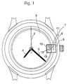
- Figure 1 shows a plan view of a timepiece 1 according to the invention.
- This timepiece includes hour indicator hands 2, 4 and 5 evolving on a dial 3 and a date 6 displaying the date of the month.
- the date consists of first 9 and second 10 indicators on which are affixed numbers respectively indicating the units 11 and the tens 12 of this calendar, this the latter appearing through a large window 13 pierced in the dial 3.
- the date that is to say the indicators 9 and 10 which compose it, is driven by a date crown 14 who travels one lap in thirty-one days and that at the rate of one step per day and this by a finger 20 actuated by a movement that comprises the timepiece, this finger being engaged on an internal toothing of the crown, this toothing being composed of thirty-one teeth 19.
- the crown 14 is arranged to drive one step a day the first indicator 9 at the end of every day except at the end of the thirty-first day when it is not not trained. This same crown 14 is arranged to drive the second indicator 10 at the end of the ninth, nineteenth, twenty-ninth and thirty-first days of the month. How to train the indicators will be described in detail below.
- the first and second indicators 9 and 10 are each provided with a device, referenced 15 and 16 respectively, allowing them to maintain a position angular defined when they are not trained.
- the invention is remarkable in that a first mechanism 17 is interposed between the crown 14 and the first indicator 9, this first mechanism being provided with means ensuring at the same time the rotation of the first indicator 9 from the crown 14 and locking this indicator when it is not driven.
- the invention is remarkable in that a second mechanism 18 is interposed between the crown 14 and the second indicator 10, this second mechanism being provided with means ensuring both the rotation of the second indicator 10 from the crown 14 and the locking of this indicator when it is not driven.
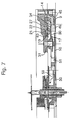
- first and second mechanisms interposed between the date crown 14 and the first and second respective indicators First we see (see more particularly the section of Figure 7) that on the crown 14 is fixed a ring 21 to drive the first mechanism 17. We also see (right part of Figure 6) that on the crown 14 is fixed a plurality of studs 22 to 25 of which only the stud 22 is visible in FIG. 7, the other studs being visible in FIGS. 4 and 5, these studs being arranged to actuate the second mechanism 18. We will now describe successively how to train and lock the indicators of the units and tens.
- the outer edge 26 of the ring 21 carried by the crown 14 includes thirty particular teeth 27 also distributed on a sector occupying the thirty-first parts of the periphery of the ring. Each tooth is preceded by a flank having an abrupt ramp 29 and then followed of a side having a gentle ramp 28 to form an outer cam to which a tooth is missing (see reference 60 in Figures 4 and 5).
- the first mechanism 17 is made of a rocker 30 pivoting on a shaft 31 secured to the movement plate.
- the first end 32 of this seesaw is fitted with a first pin 34 which is applied, under the effect of a spring 35 acting on the rocker, against the outer edge 26 of the ring 21.
- the pin 34 follows the outer edge 26 of the ring like a sliding finger on a cam.
- the flip-flop 30 is then moving back and forth, this movement occurring at the end of all the days of the month, except at the end of the thirty-first day on which the said movement has not place, the pin then follows a tooth-free path (reference 60 mentioned more high).
- the back and forth movement is reflected at the second end 33 of the rocker 30 which in turn drives, by a first spout 36 which it is provided with, a mobile 37 in rotation, this mobile being arranged to drive the first indicator 9.
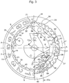
- Figures 2 and 3 also show that the first end 32 of the rocker 30 is fitted with a second pin 38 arranged to follow the inner edge 39 of the ring 21, this inner edge 39 also carrying thirty particular teeth 40 also spread over a sector occupying the thirty-first parts of the perimeter of the ring to form an inner cam with a tooth hollow missing (see reference 61 in Figures 2, 3 and 4).
- the orientation of the inner cam is arranged so that its sector 61 lacking a tooth recess is located opposite the sector 60 missing tooth on the outer cam.
- first and second pins 34 and 38 we arrange the first and second pins 34 and 38, as well as the teeth 27 and 40 arranged on the edges outside and inside 26 and 39 of the ring 21 so that when the ring is not not driven, the first pin 34 is located at the bottom of the steep ramp 29 of a teeth 41 of the outer edge of the ring, while the second pin 38 is positioned substantially at the top of one of the teeth 42 of the inner edge of the ring.
- This situation is presented in FIG. 2. Under these conditions, the flip-flop 30 is locked and it is impossible for it to inadvertently activate the mobile 37 and thereby the first indicator 9 if a shock is applied to the timepiece.
- the mobile 37 disposed between the first spout 36 of the rocker 30 and the first indicator 9 includes a star 43 profiled to be rotated by the first spout 36.
- the mobile 37 also includes a pinion 44 mounted coaxially with and secured to the star 43.
- the pinion 44 is engaged with a crown 45 provided with a internal toothing 46.
- This crown 45 supports the first indicator 9 on which are affixed the numbers 11 indicating the units of the date.
- Figures 2 and 3 finally show that the scale 30 is provided with a device 15 comprising a second spout 47 arranged to cooperate with the toothing 46 of the crown 45.
- the device 15 ensures on the one hand a defined angular position of the first indicator 9 and on the other hand the locking of the same first indicator. This situation is explained in Figure 2 where we see the second spout 47 introduced between two teeth 62 and 63 of the toothing 46 of the crown 45. It is understood here that the device 15 pursues two goals, that of indexing the indicator of the units 9 first, then that of positively locking this same indicator to prevent it from turning unexpectedly if a shock were applied to the timepiece.
- Figure 3 shows the indicator units 9 at the start of his training.
- the finger 20 driven by the movement of the timepiece begins to drive a tooth 19 of the date crown 14 which rotates with the ring 21 which is attached to it associated clockwise referenced by arrow A.
- the pin 34 of the rocker 30 climbs on the steep side of tooth 41 of ring 21 by actuating the rocker in the direction of the arrow B.
- the first spout 36 of the rocker 30 came into contact with the star 43 and slides along one of its flanks to rotate it counterclockwise referenced by arrow E.
- a wing 64 of the pinion 44 associated with the star 43 is coming into contact with a tooth 46 of the crown 45 which begins to rotate in the counterclockwise direction referenced by the arrow F, which leads to the indicator 9, which is associated with the crown 45, in the same direction F. Meanwhile, the second spout 47 of the rocker 30 is released from the teeth 62 and 63 of the crown 45 leaving the indicator units move forward one step in complete freedom.
- the gear ratio between the star 43, the pinion 44 and the teeth 46 of the crown 45 are chosen in such a way that the numbers 11 affixed to the indicator for units 9 are twenty in number, or two series of ten digits from zero to nine.
- the crown of date 14 carries four pads 22, 23, 24 and 25, these pads also serving means for fixing the ring 21 to the crown 14. These studs are arranged and angularly arranged on the crown 14 so as to rotate the second mechanism 18 at the end of the ninth, nineteenth, twenty-ninth and thirty and first day of the month.
- the second mechanism is in the form of a intermediate mobile 18 on the one hand driven by one of the four studs 22 to 25 and on the other share arranged to be in engagement with the second tens indicator 10.
- the intermediate mobile 18 comprises a first wheel 48 arranged to be advanced in rotation by the studs 22 to 25 of the date crown 14 and a second wheel 49 mounted coaxially with and integral with the first wheel 48.
- the second wheel 49 is engaged with a plate 50 provided with teeth 51.
- the plate 50 supports the second indicator 10 on which are affixed the numbers 12 indicating the tens of the date.
- Figures 4 to 6 also show that the intermediate mobile 18 comprises a lock 52 which prevents rotation of said mobile, and consequently that of the plate 50 which is linked to it, when this mobile is not driven by one of the studs 22 to 25 of the date crown 14.
- the main purpose of this lock is to block the tens indicator 10 and prevent it from moving unexpectedly if a shock is applied to the timepiece.
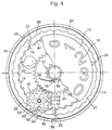
- FIG. 4 shows that two neighboring vertices 53 and 54 of the board 52 abut against a flange 55 which comprises the crown 14.
- the top 54 of the board 52 can pass in a clearance 56 made in the rim 55 of the crown as is illustrated in Figure 5.
- the situation illustrated in Figure 5 shows the passage of the twenty-ninth on the thirtieth day of the month.
- the next clearance 56 is located opposite of the stud 25 will unlock the mobile 18 during the passage of the thirty-first day to the first day of the following month.
- the finger 20 driven by the movement of the timepiece begins to drive a tooth 19 of the date crown 14 which rotates with the pads 22 to 25 which are associated with it in the clockwise direction referenced by the arrow A.
- the stud 22 drives the first wheel 48 then the second wheel 49 which is linked to it in the direction of arrow M, this second wheel in turn driving the plate 50 and the indicator 10 which is associated with it in an anti-clockwise direction referenced respectively by arrows N and P.
- the tens digit appearing in the window before the change was three ( Figure 4).
- the number of tens appearing in the window is the end of the number three and the beginning of the number zero, if the counter is at three o'clock.
- the gear ratio between the wheel 48, the wheel 49 and the tray 50 is chosen in such a way that the numbers 12 affixed on the indicator of tens 10 are twelve in number, that is to say three series of four digits going from zero at three. Indicator 10 thus turns around in three months.
- the second indicator 10 is provided with a device 16 allowing it to maintain a defined angular position when it is not causes.
- this device consists of a wheel 57 fixed under the plate 50, this wheel having teeth 58 on which a long necklace 59 whose illustrated form is only one example of embodiment.
Landscapes
- Physics & Mathematics (AREA)
- General Physics & Mathematics (AREA)
- Electromechanical Clocks (AREA)
- Pyrane Compounds (AREA)
Abstract
Description
- la figure 1 est une vue montrant l'aspect général, selon l'invention, de la pièce d'horlogerie à quantième comportant un grand guichet dans lequel apparaissent un indicateur des unités et un indicateur des dizaines du quantième,
- la figure 2 montre le mécanisme d'entraínement de l'indicateur des unités dans une phase où il est verrouillé,
- la figure 3 montre le mécanisme d'entraínement de l'indicateur des unités dans une phase où il est entraíné,
- la figure 4 montre le mécanisme d'entraínement de l'indicateur des dizaines en phase de fin de verrouillage,
- la figure 5 montre le mécanisme d'entraínement de l'indicateur des dizaines en phase d'entraínement.
- la figure 6 présente à gauche une coupe selon la ligne VIa-VIa de la figure 3, et à droite, une coupe selon la ligne Vlb-Vlb de la figure 5, et
- la figure 7 présente une coupe selon la ligne VII-VII de la figure 2,
Claims (11)
- Pièce d'horlogerie (1) comprenant des aiguilles (2, 4, 5) indicatrices de l'heure évoluant sur un cadran (3) et un quantième (6) constitué de premier (9) et second (10) indicateurs sur lesquels sont apposés des chiffres indiquant respectivement les unités (11) et les dizaines (12) dudit quantième, ce quantième apparaissant au travers d'un grand guichet (13) percé dans le cadran, ledit quantième étant entraíné par une couronne (14) de quantième faisant un tour en trente et un jours à raison d'un pas par jour, cette couronne étant arrangée pour entraíner d'un pas le premier indicateur (9) à la fin de tous les jours sauf à la fin du trente et unième jour où il n'est pas entraíné, et le second indicateur (10) à la fin des neuvième, dix-neuvième, vingt-neuvième et trente et unième jours du mois, lesdits premier et second indicateurs étant munis chacun d'un dispositif (15, 16) leur permettant de conserver une position angulaire définie quand ils ne sont pas entraínés, caractérisée par le fait qu'un premier mécanisme (17) est interposé entre la couronne (14) et le premier indicateur (9) et qu'un second mécanisme (18) est interposé entre la couronne (14) et le second indicateur (10), ces premier et second mécanismes étant pourvus chacun de moyens assurant à la fois la rotation de l'indicateur correspondant à partir de la couronne et le verrouillage desdits premier et second indicateurs quand ces derniers ne sont pas entraínés par ladite couronne.
- Pièce d'horlogerie selon la revendication 1, caractérisée par le fait que la couronne (14) porte une denture présentant trente et une dents (19), denture par laquelle cette couronne est entraínée d'un pas par jour par un doigt (20) actionné par un mouvement que comporte la pièce d'horlogerie et que sur la couronne (14) sont fixés un anneau (21) pour mouvoir le premier mécanisme (17) et une pluralité de plots (22, 23, 24, 25) arrangés pour actionner le second mécanisme (18).
- Pièce d'horlogerie selon la revendication 2, caractérisée par le fait que le bord extérieur (26) de l'anneau (21) porte trente dents (27) particulières également réparties sur un secteur occupant les trente trente et unièmes parties du pourtour de l'anneau, les flancs de chaque dent présentant respectivement une rampe abrupte (29) et une rampe douce (28), et que le premier mécanisme (17) est constitué d'une bascule (30) pivotant sur un arbre (31) solidaire du mouvement, la première extrémité (32) de la bascule étant équipée d'une première goupille (34) se trouvant appliquée, sous l'effet d'un ressort (35) agissant sur la bascule, contre le bord extérieur (26) de l'anneau (21), la bascule étant alors animée d'un mouvement de va et vient quand l'anneau est entraíné en rotation, ce mouvement se produisant à la fin de tous les jours du mois, sauf à la fin du trente et unième jour, ledit mouvement de va et vient se répercutant à la seconde extrémité (33) de la bascule laquelle entraíne à son tour, par un premier bec (36) dont elle est pourvue, un mobile (37) en rotation, ce mobile étant arrangé pour entraíner le premier indicateur (7).
- Pièce d'horlogerie selon la revendication 3, caractérisée par le fait que la première extrémité (32) de la bascule (30) est équipée d'une seconde goupille (38) arrangée pour suivre le bord intérieur (39) de l'anneau (21), ce bord intérieur portant aussi trente dents (40) particulières également réparties sur un secteur occupant les trente et trente et unièmes parties du pourtour de l'anneau, les première (34) et seconde (38) goupilles et les dents (27, 40) disposées sur les bords extérieur (26) et intérieur (39) de l'anneau (21) étant arrangées de telles façon que lorsque l'anneau n'est pas entraíné, la première goupille (34) se trouve au bas de la rampe abrupte (29) d'une (41) des dents (27) du bord extérieur de l'anneau, tandis que la seconde goupille (38) est positionnée sensiblement au sommet d'une (42) des dents (40) du bord intérieur de l'anneau, ce qui a pour effet de verrouiller la bascule (30) et d'empêcher un actionnement intempestif du mobile (37) entraínant le premier indicateur (9).
- Pièce d'horlogerie selon la revendication 3, caractérisée par le fait que le mobile (37) disposé entre le premier bec (36) de la bascule (30) et le premier indicateur (9) comprend une étoile (43) profilée pour être entraínée en rotation par ledit premier bec (36), et un pignon (4) monté coaxialement à et solidaire de l'étoile (43), ce pignon (4) étant en prise avec une couronne (45) munie d'une denture intérieure (46), cette couronne supportant le premier indicateur (9) sur lequel sont apposés les chiffres (11) indiquant les unités du quantième.
- Pièce d'horlogerie selon la revendication 5, caractérisée par le fait que la bascule (30) est munie d'un second bec (47) arrangé pour coopérer avec la denture intérieure (46) de la couronne (45) pour assurer une position angulaire définie du premier indicateur (9) et pour verrouiller ce dernier quand celui-ci n'est pas entraíné.
- Pièce d'horlogerie selon la revendication 2, caractérisée par le fait que la couronne (14) de quantième porte quatre plots (22, 23, 24, 25) arrangés pour entraíner en rotation le second mécanisme à la fin des neuvième, dix-neuvième, vingt-neuvième et trente et unième jours du mois, ce second mécanisme se présentant sous la forme d'un mobile intermédiaire (18) en prise avec le second indicateur (10).
- Pièce d'horlogerie selon la revendication 7, caractérisée par le fait que le mobile intermédiaire (18) comporte une première roue (48) arrangée pour être avancée par les plots (22, 23, 24, 25) de la couronne (14) et une seconde roue (49) montée coaxialement à et solidaire de la première roue (48), cette seconde roue (49) étant en prise avec un plateau (50) muni de dents (51), ce plateau supportant le second indicateur (10) sur lequel sont apposés les chiffres (12) indiquant les dizaines du quantième.
- Pièce d'horlogerie selon la revendication 7, caractérisée par le fait que le mobile intermédiaire (18) comporte en outre un verrou (52) empêchant la rotation dudit mobile quand il n'est pas entraíné par un des plots (22, 23, 24, 25) de la couronne (14).
- Pièce d'horlogerie selon la revendication 9, caractérisée par le fait que le verrou (52) est une planche à découpe hexagonale solidaire du mobile intermédiaire (18) et montée coaxialement à lui, deux sommets voisins (53, 54) de la planche butant contre un rebord (55) que comporte la couronne (14) quand le mobile n'est pas entraíné, ce rebord présentant des dégagements (56) dans lesquels peuvent passer lesdits sommets quand le mobile est entraíné.
- Pièce d'horlogerie selon la revendication 8, caractérisée par le fait que sous le plateau (50) muni de dents (51) est fixée un roue (57) sur les dents (58) de laquelle agit un sautoir (59) pour assurer une position angulaire définie dudit plateau (50) quand ce dernier n'est pas entraíné.
Priority Applications (3)
| Application Number | Priority Date | Filing Date | Title |
|---|---|---|---|
| EP00204732A EP1220057B1 (fr) | 2000-12-22 | 2000-12-22 | Pièce d'horlogerie pourvue d'un quantième à grand guichet |
| DE60038888T DE60038888D1 (de) | 2000-12-22 | 2000-12-22 | Uhr mit Grossdatum |
| AT00204732T ATE395636T1 (de) | 2000-12-22 | 2000-12-22 | Uhr mit grossdatum |
Applications Claiming Priority (1)
| Application Number | Priority Date | Filing Date | Title |
|---|---|---|---|
| EP00204732A EP1220057B1 (fr) | 2000-12-22 | 2000-12-22 | Pièce d'horlogerie pourvue d'un quantième à grand guichet |
Publications (2)
| Publication Number | Publication Date |
|---|---|
| EP1220057A1 true EP1220057A1 (fr) | 2002-07-03 |
| EP1220057B1 EP1220057B1 (fr) | 2008-05-14 |
Family
ID=8172513
Family Applications (1)
| Application Number | Title | Priority Date | Filing Date |
|---|---|---|---|
| EP00204732A Expired - Lifetime EP1220057B1 (fr) | 2000-12-22 | 2000-12-22 | Pièce d'horlogerie pourvue d'un quantième à grand guichet |
Country Status (3)
| Country | Link |
|---|---|
| EP (1) | EP1220057B1 (fr) |
| AT (1) | ATE395636T1 (fr) |
| DE (1) | DE60038888D1 (fr) |
Cited By (2)
| Publication number | Priority date | Publication date | Assignee | Title |
|---|---|---|---|---|
| EP1462877A3 (fr) * | 2003-03-25 | 2009-12-02 | Richemont International S.A. | Mécanisme d'affichage du quantième |
| EP3667434A1 (fr) * | 2018-12-10 | 2020-06-17 | Montres Breguet S.A. | Mécanisme d'affichage de quantième grande date et pièce d'horlogerie comprenant un tel mécanisme |
Citations (1)
| Publication number | Priority date | Publication date | Assignee | Title |
|---|---|---|---|---|
| US4257113A (en) * | 1979-04-04 | 1981-03-17 | Ebauches S.A. | Electromechanical calendar timepiece |
-
2000
- 2000-12-22 DE DE60038888T patent/DE60038888D1/de not_active Expired - Lifetime
- 2000-12-22 AT AT00204732T patent/ATE395636T1/de not_active IP Right Cessation
- 2000-12-22 EP EP00204732A patent/EP1220057B1/fr not_active Expired - Lifetime
Patent Citations (1)
| Publication number | Priority date | Publication date | Assignee | Title |
|---|---|---|---|---|
| US4257113A (en) * | 1979-04-04 | 1981-03-17 | Ebauches S.A. | Electromechanical calendar timepiece |
Cited By (3)
| Publication number | Priority date | Publication date | Assignee | Title |
|---|---|---|---|---|
| EP1462877A3 (fr) * | 2003-03-25 | 2009-12-02 | Richemont International S.A. | Mécanisme d'affichage du quantième |
| EP3667434A1 (fr) * | 2018-12-10 | 2020-06-17 | Montres Breguet S.A. | Mécanisme d'affichage de quantième grande date et pièce d'horlogerie comprenant un tel mécanisme |
| US11543777B2 (en) | 2018-12-10 | 2023-01-03 | Montres Breguet S.A. | Large date calendar display mechanism and timepiece comprising same |
Also Published As
| Publication number | Publication date |
|---|---|
| DE60038888D1 (de) | 2008-06-26 |
| ATE395636T1 (de) | 2008-05-15 |
| EP1220057B1 (fr) | 2008-05-14 |
Similar Documents
| Publication | Publication Date | Title |
|---|---|---|
| EP1586962B9 (fr) | Mécanisme de quantième perpétuel | |
| EP0756217B1 (fr) | Mécanisme de quantième annuel pour pièce d'horlogerie | |
| EP0634711B1 (fr) | Mécanisme de quantième annuel pour pièce d'horlogerie | |
| EP2073076B1 (fr) | Mécanisme de commande d'un réveil | |
| EP1536298A1 (fr) | Mécanisme de calendrier ayant des moyens d'entraínement et de correction pour deux indicateurs | |
| EP3026504A1 (fr) | Mécanisme de quantième annuel ou perpétuel et pièce d horlogerie en comportant application | |
| EP0987609B1 (fr) | Mécanisme de quantième annuel pour mouvement d'horlogerie | |
| EP3629102B1 (fr) | Mécanisme d'affichage à guichet unique | |
| EP3667434B1 (fr) | Mécanisme d'affichage de quantième grande date et pièce d'horlogerie comprenant un tel mécanisme | |
| WO2015062839A2 (fr) | Calendrier hegirien | |
| EP2444861B1 (fr) | Sélecteur de fonction | |
| EP3904964B1 (fr) | Dispositif d'affichage d'une indication horaire ou dérivée de l'heure et dispositif d'indexation | |
| EP1536299A1 (fr) | Mécanisme de quantième pour pièce d'horlogerie comprenant deux anneaux de quantième superposés | |
| EP3584643B1 (fr) | Dispositif de commande instantanée pour un affichage de quantième d'une pièce d'horlogerie | |
| EP1220057B1 (fr) | Pièce d'horlogerie pourvue d'un quantième à grand guichet | |
| EP3026505A1 (fr) | Mécanisme de quantième annuel ou perpétuel et pièce d'horlogerie en comportant application | |
| CH699794B1 (fr) | Dispositif d'aide au maintien en position d'un anneau indicateur de quantième pour pièce d'horlogerie. | |
| EP2281222B1 (fr) | Dispositif d'affichage | |
| EP1178373A1 (fr) | Pièce d'horlogerie | |
| EP3904962B1 (fr) | Dispositif d'indexation et dispositif d'affichage d'une indication horaire ou dérivée de l'heure | |
| WO2019193430A1 (fr) | Mécanisme de quantième annuel | |
| CH699143B1 (fr) | Mécanisme d'affichage. | |
| CH701406A1 (fr) | Montre-bracelet comportant un module d'affichage. | |
| EP1251412A1 (fr) | Mecanisme de quantième | |
| EP1832941B1 (fr) | Pièce d'horlogerie |
Legal Events
| Date | Code | Title | Description |
|---|---|---|---|
| PUAI | Public reference made under article 153(3) epc to a published international application that has entered the european phase |
Free format text: ORIGINAL CODE: 0009012 |
|
| AK | Designated contracting states |
Kind code of ref document: A1 Designated state(s): AT BE CH CY DE DK ES FI FR GB GR IE IT LI LU MC NL PT SE TR |
|
| AX | Request for extension of the european patent |
Free format text: AL;LT;LV;MK;RO;SI |
|
| 17P | Request for examination filed |
Effective date: 20030103 |
|
| RAP1 | Party data changed (applicant data changed or rights of an application transferred) |
Owner name: ETA SA MANUFACTURE HORLOGERE SUISSE |
|
| AKX | Designation fees paid |
Designated state(s): AT BE CH CY DE DK ES FI FR GB GR IE IT LI LU MC NL PT SE TR |
|
| 17Q | First examination report despatched |
Effective date: 20070927 |
|
| GRAP | Despatch of communication of intention to grant a patent |
Free format text: ORIGINAL CODE: EPIDOSNIGR1 |
|
| GRAS | Grant fee paid |
Free format text: ORIGINAL CODE: EPIDOSNIGR3 |
|
| GRAA | (expected) grant |
Free format text: ORIGINAL CODE: 0009210 |
|
| AK | Designated contracting states |
Kind code of ref document: B1 Designated state(s): AT BE CH CY DE DK ES FI FR GB GR IE IT LI LU MC NL PT SE TR |
|
| REG | Reference to a national code |
Ref country code: GB Ref legal event code: FG4D Free format text: NOT ENGLISH |
|
| REG | Reference to a national code |
Ref country code: CH Ref legal event code: EP |
|
| REG | Reference to a national code |
Ref country code: IE Ref legal event code: FG4D |
|
| REF | Corresponds to: |
Ref document number: 60038888 Country of ref document: DE Date of ref document: 20080626 Kind code of ref document: P |
|
| REG | Reference to a national code |
Ref country code: CH Ref legal event code: NV Representative=s name: ICB INGENIEURS CONSEILS EN BREVETS SA |
|
| PG25 | Lapsed in a contracting state [announced via postgrant information from national office to epo] |
Ref country code: FI Free format text: LAPSE BECAUSE OF FAILURE TO SUBMIT A TRANSLATION OF THE DESCRIPTION OR TO PAY THE FEE WITHIN THE PRESCRIBED TIME-LIMIT Effective date: 20080514 Ref country code: ES Free format text: LAPSE BECAUSE OF FAILURE TO SUBMIT A TRANSLATION OF THE DESCRIPTION OR TO PAY THE FEE WITHIN THE PRESCRIBED TIME-LIMIT Effective date: 20080825 |
|
| NLV1 | Nl: lapsed or annulled due to failure to fulfill the requirements of art. 29p and 29m of the patents act | ||
| PG25 | Lapsed in a contracting state [announced via postgrant information from national office to epo] |
Ref country code: NL Free format text: LAPSE BECAUSE OF FAILURE TO SUBMIT A TRANSLATION OF THE DESCRIPTION OR TO PAY THE FEE WITHIN THE PRESCRIBED TIME-LIMIT Effective date: 20080514 Ref country code: AT Free format text: LAPSE BECAUSE OF FAILURE TO SUBMIT A TRANSLATION OF THE DESCRIPTION OR TO PAY THE FEE WITHIN THE PRESCRIBED TIME-LIMIT Effective date: 20080514 |
|
| REG | Reference to a national code |
Ref country code: IE Ref legal event code: FD4D |
|
| PG25 | Lapsed in a contracting state [announced via postgrant information from national office to epo] |
Ref country code: SE Free format text: LAPSE BECAUSE OF FAILURE TO SUBMIT A TRANSLATION OF THE DESCRIPTION OR TO PAY THE FEE WITHIN THE PRESCRIBED TIME-LIMIT Effective date: 20080814 Ref country code: PT Free format text: LAPSE BECAUSE OF FAILURE TO SUBMIT A TRANSLATION OF THE DESCRIPTION OR TO PAY THE FEE WITHIN THE PRESCRIBED TIME-LIMIT Effective date: 20081014 Ref country code: IE Free format text: LAPSE BECAUSE OF FAILURE TO SUBMIT A TRANSLATION OF THE DESCRIPTION OR TO PAY THE FEE WITHIN THE PRESCRIBED TIME-LIMIT Effective date: 20080514 Ref country code: DK Free format text: LAPSE BECAUSE OF FAILURE TO SUBMIT A TRANSLATION OF THE DESCRIPTION OR TO PAY THE FEE WITHIN THE PRESCRIBED TIME-LIMIT Effective date: 20080514 |
|
| PLBE | No opposition filed within time limit |
Free format text: ORIGINAL CODE: 0009261 |
|
| STAA | Information on the status of an ep patent application or granted ep patent |
Free format text: STATUS: NO OPPOSITION FILED WITHIN TIME LIMIT |
|
| 26N | No opposition filed |
Effective date: 20090217 |
|
| BERE | Be: lapsed |
Owner name: ETA SA MANUFACTURE HORLOGERE SUISSE Effective date: 20081231 |
|
| PG25 | Lapsed in a contracting state [announced via postgrant information from national office to epo] |
Ref country code: MC Free format text: LAPSE BECAUSE OF NON-PAYMENT OF DUE FEES Effective date: 20081231 |
|
| PG25 | Lapsed in a contracting state [announced via postgrant information from national office to epo] |
Ref country code: IT Free format text: LAPSE BECAUSE OF FAILURE TO SUBMIT A TRANSLATION OF THE DESCRIPTION OR TO PAY THE FEE WITHIN THE PRESCRIBED TIME-LIMIT Effective date: 20080514 |
|
| PG25 | Lapsed in a contracting state [announced via postgrant information from national office to epo] |
Ref country code: BE Free format text: LAPSE BECAUSE OF NON-PAYMENT OF DUE FEES Effective date: 20081231 |
|
| PG25 | Lapsed in a contracting state [announced via postgrant information from national office to epo] |
Ref country code: CY Free format text: LAPSE BECAUSE OF FAILURE TO SUBMIT A TRANSLATION OF THE DESCRIPTION OR TO PAY THE FEE WITHIN THE PRESCRIBED TIME-LIMIT Effective date: 20080514 Ref country code: LU Free format text: LAPSE BECAUSE OF NON-PAYMENT OF DUE FEES Effective date: 20081222 |
|
| PG25 | Lapsed in a contracting state [announced via postgrant information from national office to epo] |
Ref country code: TR Free format text: LAPSE BECAUSE OF FAILURE TO SUBMIT A TRANSLATION OF THE DESCRIPTION OR TO PAY THE FEE WITHIN THE PRESCRIBED TIME-LIMIT Effective date: 20080514 |
|
| PG25 | Lapsed in a contracting state [announced via postgrant information from national office to epo] |
Ref country code: GR Free format text: LAPSE BECAUSE OF FAILURE TO SUBMIT A TRANSLATION OF THE DESCRIPTION OR TO PAY THE FEE WITHIN THE PRESCRIBED TIME-LIMIT Effective date: 20080815 |
|
| PGFP | Annual fee paid to national office [announced via postgrant information from national office to epo] |
Ref country code: GB Payment date: 20101201 Year of fee payment: 11 |
|
| GBPC | Gb: european patent ceased through non-payment of renewal fee |
Effective date: 20111222 |
|
| PG25 | Lapsed in a contracting state [announced via postgrant information from national office to epo] |
Ref country code: GB Free format text: LAPSE BECAUSE OF NON-PAYMENT OF DUE FEES Effective date: 20111222 |
|
| REG | Reference to a national code |
Ref country code: FR Ref legal event code: PLFP Year of fee payment: 16 |
|
| PGFP | Annual fee paid to national office [announced via postgrant information from national office to epo] |
Ref country code: DE Payment date: 20151119 Year of fee payment: 16 |
|
| PGFP | Annual fee paid to national office [announced via postgrant information from national office to epo] |
Ref country code: FR Payment date: 20151123 Year of fee payment: 16 |
|
| REG | Reference to a national code |
Ref country code: DE Ref legal event code: R119 Ref document number: 60038888 Country of ref document: DE |
|
| REG | Reference to a national code |
Ref country code: FR Ref legal event code: ST Effective date: 20170831 |
|
| PG25 | Lapsed in a contracting state [announced via postgrant information from national office to epo] |
Ref country code: FR Free format text: LAPSE BECAUSE OF NON-PAYMENT OF DUE FEES Effective date: 20170102 |
|
| PG25 | Lapsed in a contracting state [announced via postgrant information from national office to epo] |
Ref country code: DE Free format text: LAPSE BECAUSE OF NON-PAYMENT OF DUE FEES Effective date: 20170701 |
|
| PGFP | Annual fee paid to national office [announced via postgrant information from national office to epo] |
Ref country code: CH Payment date: 20191121 Year of fee payment: 20 |