EP1219999A1 - Pre-stressed ribbon stack - Google Patents
Pre-stressed ribbon stack Download PDFInfo
- Publication number
- EP1219999A1 EP1219999A1 EP01403106A EP01403106A EP1219999A1 EP 1219999 A1 EP1219999 A1 EP 1219999A1 EP 01403106 A EP01403106 A EP 01403106A EP 01403106 A EP01403106 A EP 01403106A EP 1219999 A1 EP1219999 A1 EP 1219999A1
- Authority
- EP
- European Patent Office
- Prior art keywords
- ribbons
- stack
- ribbon stack
- stress
- ribbon
- Prior art date
- Legal status (The legal status is an assumption and is not a legal conclusion. Google has not performed a legal analysis and makes no representation as to the accuracy of the status listed.)
- Withdrawn
Links
- 238000009826 distribution Methods 0.000 claims abstract description 54
- 230000006835 compression Effects 0.000 claims abstract description 27
- 238000007906 compression Methods 0.000 claims abstract description 27
- 239000013307 optical fiber Substances 0.000 claims abstract description 15
- 238000003475 lamination Methods 0.000 claims description 23
- 238000010030 laminating Methods 0.000 claims description 4
- 238000000034 method Methods 0.000 claims 10
- 230000007423 decrease Effects 0.000 claims 1
- 230000000930 thermomechanical effect Effects 0.000 abstract description 6
- 238000005452 bending Methods 0.000 description 20
- 239000000835 fiber Substances 0.000 description 16
- 230000015572 biosynthetic process Effects 0.000 description 3
- 230000000694 effects Effects 0.000 description 3
- 230000001965 increasing effect Effects 0.000 description 3
- 238000006073 displacement reaction Methods 0.000 description 2
- 238000012986 modification Methods 0.000 description 2
- 230000004048 modification Effects 0.000 description 2
- 230000001939 inductive effect Effects 0.000 description 1
- 230000003287 optical effect Effects 0.000 description 1
- 229920001169 thermoplastic Polymers 0.000 description 1
- 239000012815 thermoplastic material Substances 0.000 description 1
- 239000004416 thermosoftening plastic Substances 0.000 description 1
Images




Classifications
-
- G—PHYSICS
- G02—OPTICS
- G02B—OPTICAL ELEMENTS, SYSTEMS OR APPARATUS
- G02B6/00—Light guides; Structural details of arrangements comprising light guides and other optical elements, e.g. couplings
- G02B6/44—Mechanical structures for providing tensile strength and external protection for fibres, e.g. optical transmission cables
- G02B6/4479—Manufacturing methods of optical cables
- G02B6/448—Ribbon cables
-
- G—PHYSICS
- G02—OPTICS
- G02B—OPTICAL ELEMENTS, SYSTEMS OR APPARATUS
- G02B6/00—Light guides; Structural details of arrangements comprising light guides and other optical elements, e.g. couplings
- G02B6/44—Mechanical structures for providing tensile strength and external protection for fibres, e.g. optical transmission cables
- G02B6/4401—Optical cables
- G02B6/441—Optical cables built up from sub-bundles
- G02B6/4411—Matrix structure
Definitions
- the present invention relates generally to a fiber optic cable having a pre-stressed ribbon stack, and more particularly to a cable having stacked ribbons which are pre-stressed according to a distribution that corresponds to expected thermo-mechanical conditions to occur during the service of the cable.
- the comer fibers experience a high level of attenuation, which reduces the cable's performance characteristics and limits the level of recommended thermo-mechanical loads.
- the comer fibers 41a of the laminated ribbon stack 41 of the fiber optic cable 40 are located the most remotely from the geometrical center of the ribbon stack. Consequently, under mechanical bending and contact stresses from surrounding cable components such as buffer tube 42, the comer fibers 41a usually have maximum stress levels as compared with the centrally located fibers.
- the thermoplastic material of the buffer tube 42 expands and contracts in both longitudinal and radial directions.
- an optical fiber ribbon stack in which some of the optical fiber ribbons are pre-stressed according to a predetermined tension/compression distribution before being laminated together in a stack.
- This distribution corresponds to expected thermo-mechanical conditions which occur during the service of the cable housing the ribbon stack, and may be linear or non-linear, symmetric or non-symmetric, including anti-symmetric.
- the present invention resides in providing a ribbon stack in which the individual ribbons are pre-stressed before being laminated together.
- the ribbons are pre-stressed according to a stress distribution that corresponds to the thermo-mechanical conditions that are expected during the cable's service.
- the stress distribution is either a non-linear or linear curve across the ribbon stack's thickness ( i.e ., from one outer most ribbon to the other).
- the stress distribution may include compression stresses (designated as negative values) as well as tensile stresses (designated as positive values).
- Fig. 1(a) illustrates a side view of a laminated ribbon stack 10 symmetrically pre-stressed according to a first embodiment of the present invention.
- the non-linear symmetric stress distribution avoids attenuation due to expected mechanical tension and bending about a point or axis.
- the ribbon stack 10 includes an upper most ribbon 11, a lower most ribbon 12, and other ribbons therebetween.
- the outer most ribbons i.e ., the upper most and lower most ribbons
- the inner ribbons are pre-stretched. This pre-compression/prestretching is accomplished by stretching the inner ribbons to a greater degree than the outer ribbons, and then laminating the ribbons together in the form of a ribbon stack. After lamination the more greatly stretched inner ribbons will have a stronger tendency to relax and return to their original state, resulting in a compression force being imparted on the outer most ribbons (shown as a negative value in Fig. 1(a)) and a tensile force remaining on the inner ribbons (shown as a positive value in Fig. 1(a)).
- FIG. 1(a) shows a ribbon stack of six ribbons horizontally laid on top of one another.
- the upper portion of the figure shows the ribbon stack after the tensile stresses are imparted onto the ribbons but prior to lamination, and the lower portion of the figure shows the ribbon stack after lamination.
- the numbers represent grams of force, typically applied per individual fiber, a positive number being a tensile force and a negative number being a compression force.
- each of the ribbons Prior to lamination each of the ribbons is subjected to a particular tensile force.
- the inner ribbons are subjected to a larger tensile force than the outer ribbons.
- the two inner-most ribbons are subjected to a tensile force of 120 grams
- the next two inner most ribbons are subjected to a tensile force of 95 grams
- the outer ribbons are subjected to a tensile force of 60 grams. None of the individual ribbons is compressed before lamination.
- the stressed ribbons are laminated together to form a laminated ribbon stack. Due to elastic unloading, the varying tensile forces of the individual ribbons counteract each other to form a residual or final stress distribution across the ribbon stack. That is, the ribbons with the larger tensile forces will have a greater tendency to shrink back to their stress-free states, thereby imparting compression forces on the ribbons with the smaller tensile forces. More specifically, the stress on each ribbon of the laminated ribbon stack is approximately equal to the difference between the particular ribbon's pre-lamination tensile stress and the average tensile stress across the width ( i.e ., from top to bottom) of the pre-lamination ribbon stack. In the example of Fig.
- the average pre-lamination tensile force is approximately 92 grams, and thus the post-lamination or residual stresses of the inner most ribbons is 29 grams, the next inner most ribbons is 3 grams and the outer most ribbons is -32 grams, the negative number indicating a compression stress.
- This example laminated ribbon stack 10 has a symmetric stress distribution, and is shown in the bottom portion of Fig. 1(c).
- Fig. 5(a) illustrates a side isometric view of an ordinary (i.e ., non-pre-stressed) laminated ribbon stack 50 stretched and bent with respect to a point or axis A.
- this ribbon stack 50 is stretched and bent about the point or axis A, the resulting stress distribution across the ribbon stack 50 is as shown in Fig. 5(b).
- the top ribbon 51 has a higher tensile stress (and associated micro-bending) as compared with the other ribbons in the stack 50.
- FIG. 1(d) This example is a ribbon stack of six ribbons horizontal laid on top of one another.
- the upper portion of the figure shows the stress distribution of the ribbon stack after lamination in accordance with the invention
- the middle portion shows the stress distribution of an ordinary ribbon stack stretched and bent with respect to a point or axis (as discussed with respect to Figs. 5(a) and 5(b))
- the lower portion of the figure shows the stress distribution of the pre-stressed ribbon stack of the present invention when stretched and bent in such a manner.
- the numbers represent grams of force, a positive number being a tensile force and a negative number being a compression force. As shown in the lower portion of Fig. 1(d), there is a resulting tensile force of 48 grams on the upper ribbon and a compression force of -2 grams on the lower ribbon. These forces have significantly lower absolute values than the tensile force of 80 grams on the upper ribbon of the ordinary stack and 30 grams on the lower ribbon observed in the regular case of non-pre-stressed ribbon stacks. The result is a ribbon stack having comer fibers of the upper and lower ribbons less subjected to micro-bending and attenuation.
- Fig. 2(a) illustrates a side view of a laminated ribbon stack 20 symmetrically pre-stressed according to a second embodiment of the present invention. This symmetric, non-linear stress distribution avoids attenuation that can be caused by cold temperatures.
- the ribbon stack 20 includes an upper most ribbon 21, a lower most ribbon 22 and other ribbons therebetween.
- the outer most ribbons are pre-stretched, while the inner most ribbons are pre-compressed. This pre-stretching/pre-compression is accomplished by stretching the outer ribbons to a greater degree than the inner ribbons, and then laminating the ribbons together in the form of a ribbon stack 20. After lamination the more greatly stretched outer ribbons 21, 22 will have higher elastic unloading forces to return to their stress-free state. This result in a compression force being imparted on the inner ribbons (shown as a negative value in Fig. 2(a)) and a tensile force remaining on the outer ribbons (shown as a positive value in Fig. 2(a)) when the state of equilibrium of the stack is achieved.
- FIG. 2(a) shows a ribbon stack of six ribbons horizontal laid on top of one another.
- the upper portion of the figure shows the ribbon stack after the tensile stresses are imparted onto the ribbons but prior to lamination, and the lower portion of the figure shows the ribbon stack after lamination.
- each of the inner ribbons Prior to lamination each of the inner ribbons are subjected to a larger tensile force than the outer ribbons.
- the two inner-most ribbons are subjected to a tensile force of 90 grams
- the two next ribbons are subjected to a tensile force of 110 grams
- the outer ribbons are subjected to a tensile force of 120 grams.
- the stressed ribbons are laminated together to form a laminated ribbon stack.
- the varying tensile forces of the individual ribbons then counteract each other to form a stress distribution across the ribbon stack. That is, the ribbons with the larger tensile forces will have greater elastic unloading forces to move back to their stress-free states, thereby imparting compression forces on the ribbons with the smaller tensile forces.
- the result is a symmetric stress distribution as shown in the bottom portion of Fig. 2(c).
- the post-lamination stresses of the inner most ribbons is -16 grams, which is a compression force
- the next inner most ribbons is 3 grams and the outer most ribbons is 13.
- Fig. 6 illustrates a side view of an ordinary (i . e ., non-pre-stressed) laminated ribbon stack 60 that is subjected to a cold temperature.
- the force of the shrinking displacement of the thermoplastic buffer tube is transmitted to the ribbon stack 60 superimposing stresses of compression on the outer most ribbons 61, 62 and comer fibers of these ribbons.
- the pre-stressed ribbon stack 20 of Fig. 2(a) subjected to cold temperatures will now be explained in more detail with reference to the example illustrated in Fig. 2(d).
- This figure uses as an example a ribbon stack of six ribbons horizontal laid on top of one another.
- the upper portion of the figure shows the stress distribution of the ribbon stack 20 after lamination
- the middle portion shows the stress distribution of an ordinary (i.e ., non-pre-stressed) ribbon stack subjected to cold temperatures (as discussed with respect to Fig. 6)
- the lower portion of the figure shows the stress distribution of the pre-stressed ribbon stack when subjected to cold.
- the resulting stress in the upper most and lower most ribbons are equal to zero. Consequently, the comer fibers of the pre-stressed ribbon stack 20 can be subjected to much lower temperatures in order to reach levels of thermally induced stress, in which excessive levels of compression stresses typically cause localized micro-bending and buckling of fibers along with associated attenuation problems.
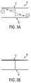
- Fig. 3(a) illustrates a side view of a laminated ribbon stack 30 non-symmetrically pre-stressed according to a third embodiment of the present invention.
- This non-symmetric stress distribution results in a pre-curved ribbon stack and can be used to reduce attenuation under mechanical bending with respect to the axis of the ribbon stack, or can be advantageously used for twist and helical stranding of ribbon stacks.
- Other linear or non-linear stress distribution curves including anti-symmetric, non-linear distributions can be used for these purposes.
- the stress distributions are symmetric. Symmetric stress distributions occur when the outer ribbons are pre-stressed equally and the distribution of stresses through the ribbon stack is symmetric, thereby resulting in the final shape of the ribbon stack being straight.
- the stress distribution of the third embodiment is non-symmetric and thus results in a ribbon stack that is curved or twisted.
- the ribbon stack 30 includes an upper most ribbon 31, a lower most ribbon 32, and other ribbons therebetween.
- the upper half of the ribbon stack 30, including the upper most ribbon 31, is pre-stretched.
- the lower half of the stack 30, including the lower most ribbon 32 is pre-compressed, but not enough to buckle the ribbons.
- This pre-stretching/pre-compression is accomplished by stretching the upper ribbons to a greater degree than the lower ribbons, and then laminating the ribbons together in the form of a ribbon stack. After lamination the more greatly stretched upper ribbons will have higher force of elastic unloading to return to their stress-free state, resulting in a compression force being imparted on the lower ribbons (shown as a negative value in Fig. 3(a)) and a tensile force remaining in the upper ribbons (shown as a positive value in Fig. 3(a)).
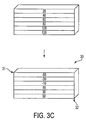
- FIG. 3(a) shows a ribbon stack of six ribbons horizontal laid on top of one another.
- the upper portion of the figure shows the ribbon stack after the tensile stresses are imparted onto the ribbons but prior to lamination, and the lower portion of the figure shows the ribbon stack after lamination.
- the upper ribbons Prior to lamination the upper ribbons are subjected to a larger tensile force than the lower ribbons.
- the ribbons are subjected to a forces of 120, 100, 80, 60, and 20 grams, respectively, from the lower most ribbon to the upper most ribbon.
- the stressed ribbons are laminated together to form a laminated ribbon stack.
- the varying tensile forces of the individual ribbons then counteract each other to form a stress distribution across the ribbon stack. That is, the ribbons with the larger tensile forces will have higher elastic unloading force to shrink back to their zero-stress states, thereby imparting compression forces on the ribbons with the smaller tensile forces.
- the result is a laminated ribbon stack having an anti-symmetric stress distribution as shown in the bottom portion of Fig. 3(c).
- Fig. 7(a) illustrates a side isometric view of a non-pre-stressed laminated ribbon stack 70 subjected to pure bending with respect to the axis of the ribbon stack
- Fig. 7(b) illustrates a side view of the ribbon stack of Fig. 7(a) with a stress distribution resulting from bending with respect to the axis of the ribbon stack.
- the resulting levels of stresses (and associated micro-bending) on the top ribbon 71 and bottom ribbon 72 are significant as compared with the other ribbons in the stack 70.
- the level of bending stress in the stack can be significantly reduced by pre-stressing the ribbon stack according to the stress distribution shown in Fig. 3(a), discussed above.
- the pre-compression in the upper most ribbon 31 and the pre-tensile stress in the lower most ribbon 72 are compensated by the stress distribution due to the stack bending, thereby altogether reducing the stress levels in the top and bottom ribbons 31, 32 that would have otherwise occurred.
- Fig. 3(b) shows the stresses in which the whole stack including the upper most ribbon 31 and the lower most ribbon 32 being virtually eliminated.
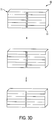
- FIG. 3(d) The bending of the pre-stressed ribbon stack 30 of Fig. 3(a) will now be explained in more detail with reference to the example illustrated in Fig. 3(d).
- This figure uses as an example a ribbon stack of six ribbons horizontal laid on top of one another.
- the upper portion of the figure shows the stress distribution of the ribbon stack 30 after lamination
- the middle portion shows the stress distribution of an ordinary ribbon stack bent with respect its axis (as discussed with respect to Figs. 7(a) and 7(b))
- the lower portion of the figure shows the stress distribution of the pre-stressed ribbon stack when bent in such a manner.
- resulting stress in the stack is equal to zero.
- the pre-stressed ribbon stack 30 of the third embodiment is curved or twisted due to its non-symmetric stress distribution.
- the curvature of the ribbon stacks may be used to improve performance of the cable. That is, pre-curved ribbons can "naturally" accommodate subsequent curvilinear (e.g. helical) paths without inducing an additional bending of the stack, for example during the stack stranding in the slotted core.
Landscapes
- Physics & Mathematics (AREA)
- General Physics & Mathematics (AREA)
- Optics & Photonics (AREA)
- Engineering & Computer Science (AREA)
- Manufacturing & Machinery (AREA)
- Fuel Cell (AREA)
Abstract
An optical fiber ribbon stack in which individual ribbons (11, 12) are prestressed according to a predetermined tension/compression distribution before being laminated together in a stack (10). This distribution corresponds to expected thermomechanical conditions which occur during the service of the cable housing the ribbon stack, and may be linear or non-linear, symmetric or non-symmetric, producing straight or curved stacks. <IMAGE>
Description
The present invention relates generally to a fiber optic cable having a pre-stressed
ribbon stack, and more particularly to a cable having stacked ribbons which are
pre-stressed according to a distribution that corresponds to expected thermo-mechanical
conditions to occur during the service of the cable.
In fiber optic cables with stranded, twisted, or straight ribbon stacks, the
comer fibers experience a high level of attenuation, which reduces the cable's
performance characteristics and limits the level of recommended thermo-mechanical
loads. As shown in Fig. 4, the comer fibers 41a of the laminated ribbon stack 41 of
the fiber optic cable 40 are located the most remotely from the geometrical center of
the ribbon stack. Consequently, under mechanical bending and contact stresses from
surrounding cable components such as buffer tube 42, the comer fibers 41a usually
have maximum stress levels as compared with the centrally located fibers. Moreover,
under thermal loading, the thermoplastic material of the buffer tube 42 expands and
contracts in both longitudinal and radial directions. Corresponding displacement of
the thermally loaded buffer tube 42 places an additional stress on the comer fibers
41a. The attenuation in the comer fibers 41a of the ribbon stack 41 may be reduced
by increasing the gap between the comers of the ribbon stack 41 and the buffer tube
42 (i.e., by providing a larger buffer tube). But this approach leads to an undesirable
increase in the cable diameter.
It is an object of the present invention to improve the optical performance of the
cable through increased thermo-mechanical load resistance of a cable in which a
laminated ribbon stack is provided.
It is a further object of the present invention to reduce the attenuation
experienced by the comer fibers of an optical fiber ribbon stack provided in a cable,
without increasing the diameter of the cable.
These objects are fulfilled by constructing an optical fiber ribbon stack in
which some of the optical fiber ribbons are pre-stressed according to a predetermined
tension/compression distribution before being laminated together in a stack. This
distribution corresponds to expected thermo-mechanical conditions which occur
during the service of the cable housing the ribbon stack, and may be linear or non-linear,
symmetric or non-symmetric, including anti-symmetric.
The above objects and advantages of the present invention will become more
apparent by describing in detail a preferred embodiment thereof with reference to the
attached drawings in which:
The present invention resides in providing a ribbon stack in which the
individual ribbons are pre-stressed before being laminated together. The ribbons are
pre-stressed according to a stress distribution that corresponds to the thermo-mechanical
conditions that are expected during the cable's service. The stress
distribution is either a non-linear or linear curve across the ribbon stack's thickness
(i.e., from one outer most ribbon to the other). The stress distribution may include
compression stresses (designated as negative values) as well as tensile stresses
(designated as positive values).
Fig. 1(a) illustrates a side view of a laminated ribbon stack 10 symmetrically
pre-stressed according to a first embodiment of the present invention. The non-linear
symmetric stress distribution avoids attenuation due to expected mechanical tension
and bending about a point or axis.
The ribbon stack 10 includes an upper most ribbon 11, a lower most ribbon 12,
and other ribbons therebetween. The outer most ribbons (i.e., the upper most and
lower most ribbons) are pre-compressed, but not enough to buckle the ribbons. The
inner ribbons, on the other hand, are pre-stretched. This pre-compression/prestretching
is accomplished by stretching the inner ribbons to a greater degree than the
outer ribbons, and then laminating the ribbons together in the form of a ribbon stack.
After lamination the more greatly stretched inner ribbons will have a stronger
tendency to relax and return to their original state, resulting in a compression force
being imparted on the outer most ribbons (shown as a negative value in Fig. 1(a)) and
a tensile force remaining on the inner ribbons (shown as a positive value in Fig. 1(a)).
The formation of the pre-stressed laminated ribbon stack 10 shown in Fig. 1(a)
will now be explained in more detail with reference to the example illustrated in Fig.
1(c). This figure shows a ribbon stack of six ribbons horizontally laid on top of one
another. The upper portion of the figure shows the ribbon stack after the tensile
stresses are imparted onto the ribbons but prior to lamination, and the lower portion of
the figure shows the ribbon stack after lamination. The numbers represent grams of
force, typically applied per individual fiber, a positive number being a tensile force
and a negative number being a compression force.
Prior to lamination each of the ribbons is subjected to a particular tensile force.
The inner ribbons are subjected to a larger tensile force than the outer ribbons. In the
example shown in Fig. 1(c), the two inner-most ribbons are subjected to a tensile
force of 120 grams, the next two inner most ribbons are subjected to a tensile force of
95 grams, and the outer ribbons are subjected to a tensile force of 60 grams. None of
the individual ribbons is compressed before lamination.
The stressed ribbons are laminated together to form a laminated ribbon stack.
Due to elastic unloading, the varying tensile forces of the individual ribbons
counteract each other to form a residual or final stress distribution across the ribbon
stack. That is, the ribbons with the larger tensile forces will have a greater tendency
to shrink back to their stress-free states, thereby imparting compression forces on the
ribbons with the smaller tensile forces. More specifically, the stress on each ribbon of
the laminated ribbon stack is approximately equal to the difference between the
particular ribbon's pre-lamination tensile stress and the average tensile stress across
the width (i.e., from top to bottom) of the pre-lamination ribbon stack. In the example
of Fig. 1(c), the average pre-lamination tensile force is approximately 92 grams, and
thus the post-lamination or residual stresses of the inner most ribbons is 29 grams, the
next inner most ribbons is 3 grams and the outer most ribbons is -32 grams, the
negative number indicating a compression stress. This example laminated ribbon
stack 10 has a symmetric stress distribution, and is shown in the bottom portion of
Fig. 1(c).
The stresses resulting from simultaneous stretching and bending a ribbon stack
with respect to a point or axis will now be explained.
Fig. 5(a) illustrates a side isometric view of an ordinary (i.e., non-pre-stressed)
laminated ribbon stack 50 stretched and bent with respect to a point or axis A. When
this ribbon stack 50 is stretched and bent about the point or axis A, the resulting stress
distribution across the ribbon stack 50 is as shown in Fig. 5(b). The top ribbon 51 has
a higher tensile stress (and associated micro-bending) as compared with the other
ribbons in the stack 50.
High levels of stress caused by stretching and bending in the top ribbon of the
stack can be significantly reduced by pre-stressing the ribbon stack according to the
stress distribution shown in Fig. 1(a), discussed above. When this pre-stressed ribbon
stack 10 is bent, the pre-compression in the outer most ribbon is compensated with the
induced tensile stress in the top ribbon 11. This stress compensation effect is depicted
in Fig. 1(b), which shows the stress on the top ribbon 11 not being nearly as great as
that of the top ribbon 51 of the ordinary (non-pre-stressed) stack 50 of Fig. 5(b).
The stretching and bending of the pre-stressed ribbon stack 10 of Fig. 1(a) will
now be explained in more detail with reference to the example illustrated in Fig. 1(d).
This example is a ribbon stack of six ribbons horizontal laid on top of one another.
The upper portion of the figure shows the stress distribution of the ribbon stack after
lamination in accordance with the invention, the middle portion shows the stress
distribution of an ordinary ribbon stack stretched and bent with respect to a point or
axis (as discussed with respect to Figs. 5(a) and 5(b)), and the lower portion of the
figure shows the stress distribution of the pre-stressed ribbon stack of the present
invention when stretched and bent in such a manner. The numbers represent grams of
force, a positive number being a tensile force and a negative number being a
compression force. As shown in the lower portion of Fig. 1(d), there is a resulting
tensile force of 48 grams on the upper ribbon and a compression force of -2 grams on
the lower ribbon. These forces have significantly lower absolute values than the
tensile force of 80 grams on the upper ribbon of the ordinary stack and 30 grams on
the lower ribbon observed in the regular case of non-pre-stressed ribbon stacks. The
result is a ribbon stack having comer fibers of the upper and lower ribbons less
subjected to micro-bending and attenuation.
Second Embodiment:
Fig. 2(a) illustrates a side view of a laminated ribbon stack 20 symmetrically
pre-stressed according to a second embodiment of the present invention. This
symmetric, non-linear stress distribution avoids attenuation that can be caused by cold
temperatures.
The ribbon stack 20 includes an upper most ribbon 21, a lower most ribbon 22
and other ribbons therebetween. The outer most ribbons are pre-stretched, while the
inner most ribbons are pre-compressed. This pre-stretching/pre-compression is
accomplished by stretching the outer ribbons to a greater degree than the inner
ribbons, and then laminating the ribbons together in the form of a ribbon stack 20.
After lamination the more greatly stretched outer ribbons 21, 22 will have higher
elastic unloading forces to return to their stress-free state. This result in a
compression force being imparted on the inner ribbons (shown as a negative value in
Fig. 2(a)) and a tensile force remaining on the outer ribbons (shown as a positive
value in Fig. 2(a)) when the state of equilibrium of the stack is achieved.
The formation of the laminated ribbon stack 20 shown in Fig. 2(a) will now be
explained in more detail with reference to the example illustrated in Fig. 2(c). This
figure shows a ribbon stack of six ribbons horizontal laid on top of one another. The
upper portion of the figure shows the ribbon stack after the tensile stresses are
imparted onto the ribbons but prior to lamination, and the lower portion of the figure
shows the ribbon stack after lamination.
Prior to lamination each of the inner ribbons are subjected to a larger tensile
force than the outer ribbons. In the example shown in Fig. 2(c), the two inner-most
ribbons are subjected to a tensile force of 90 grams, the two next ribbons are subjected
to a tensile force of 110 grams, and the outer ribbons are subjected to a tensile force of
120 grams.
The stressed ribbons are laminated together to form a laminated ribbon stack.
The varying tensile forces of the individual ribbons then counteract each other to form
a stress distribution across the ribbon stack. That is, the ribbons with the larger tensile
forces will have greater elastic unloading forces to move back to their stress-free
states, thereby imparting compression forces on the ribbons with the smaller tensile
forces. When the state of equilibrium of the stack is achieved, the result is a
symmetric stress distribution as shown in the bottom portion of Fig. 2(c). The post-lamination
stresses of the inner most ribbons is -16 grams, which is a compression
force, the next inner most ribbons is 3 grams and the outer most ribbons is 13.
The stresses on the ribbon stack 20 resulting from the cable, which houses the
stack 20, being subjected to cold temperatures will now be explained.
Fig. 6 illustrates a side view of an ordinary (i.e., non-pre-stressed) laminated
ribbon stack 60 that is subjected to a cold temperature. When the cable housing of this
ribbon stack 60 is subjected to a cold environment, the force of the shrinking
displacement of the thermoplastic buffer tube is transmitted to the ribbon stack 60
superimposing stresses of compression on the outer most ribbons 61, 62 and comer
fibers of these ribbons.
The negative effects cold temperatures have on the comer fibers of the top
ribbon 61 of the stack 60 can be significantly reduced by pre-stressing the ribbon
stack with tensile forces according to the stress distribution shown in Fig. 2(a),
discussed above. When the this pre-stressed ribbon stack 20 is subjected to cold
environments, the superposition of thermal compression and pre-existing tensile force
in the outer most ribbons 21, 22 will favorably reduce stresses on the outer ribbons 21,
22 that would have otherwise occurred. This resulting stress distribution is depicted
in Fig. 2(b).
The pre-stressed ribbon stack 20 of Fig. 2(a) subjected to cold temperatures
will now be explained in more detail with reference to the example illustrated in Fig.
2(d). This figure uses as an example a ribbon stack of six ribbons horizontal laid on
top of one another. The upper portion of the figure shows the stress distribution of the
ribbon stack 20 after lamination, the middle portion shows the stress distribution of an
ordinary (i.e., non-pre-stressed) ribbon stack subjected to cold temperatures (as
discussed with respect to Fig. 6), and the lower portion of the figure shows the stress
distribution of the pre-stressed ribbon stack when subjected to cold. As shown in the
lower portion of Fig. 2(d), the resulting stress in the upper most and lower most
ribbons are equal to zero. Consequently, the comer fibers of the pre-stressed ribbon
stack 20 can be subjected to much lower temperatures in order to reach levels of
thermally induced stress, in which excessive levels of compression stresses typically
cause localized micro-bending and buckling of fibers along with associated
attenuation problems.
Fig. 3(a) illustrates a side view of a laminated ribbon stack 30 non-symmetrically
pre-stressed according to a third embodiment of the present invention.
This non-symmetric stress distribution results in a pre-curved ribbon stack and can be
used to reduce attenuation under mechanical bending with respect to the axis of the
ribbon stack, or can be advantageously used for twist and helical stranding of ribbon
stacks. Other linear or non-linear stress distribution curves including anti-symmetric,
non-linear distributions can be used for these purposes.
In the first two embodiments the stress distributions are symmetric.
Symmetric stress distributions occur when the outer ribbons are pre-stressed equally
and the distribution of stresses through the ribbon stack is symmetric, thereby
resulting in the final shape of the ribbon stack being straight. The stress distribution
of the third embodiment is non-symmetric and thus results in a ribbon stack that is
curved or twisted.
Returning to Fig. 3(a), the ribbon stack 30 includes an upper most ribbon 31, a
lower most ribbon 32, and other ribbons therebetween. The upper half of the ribbon
stack 30, including the upper most ribbon 31, is pre-stretched. The lower half of the
stack 30, including the lower most ribbon 32, is pre-compressed, but not enough to
buckle the ribbons. This pre-stretching/pre-compression is accomplished by
stretching the upper ribbons to a greater degree than the lower ribbons, and then
laminating the ribbons together in the form of a ribbon stack. After lamination the
more greatly stretched upper ribbons will have higher force of elastic unloading to
return to their stress-free state, resulting in a compression force being imparted on the
lower ribbons (shown as a negative value in Fig. 3(a)) and a tensile force remaining in
the upper ribbons (shown as a positive value in Fig. 3(a)).
The formation of the laminated ribbon stack 30 shown in Fig. 3(a) will now be
explained in more detail with reference to the example illustrated in Fig. 3(c). This
figure shows a ribbon stack of six ribbons horizontal laid on top of one another. The
upper portion of the figure shows the ribbon stack after the tensile stresses are
imparted onto the ribbons but prior to lamination, and the lower portion of the figure
shows the ribbon stack after lamination.
Prior to lamination the upper ribbons are subjected to a larger tensile force
than the lower ribbons. In the example shown in Fig. 3(c), the ribbons are subjected
to a forces of 120, 100, 80, 60, and 20 grams, respectively, from the lower most
ribbon to the upper most ribbon.
The stressed ribbons are laminated together to form a laminated ribbon stack.
The varying tensile forces of the individual ribbons then counteract each other to form
a stress distribution across the ribbon stack. That is, the ribbons with the larger tensile
forces will have higher elastic unloading force to shrink back to their zero-stress
states, thereby imparting compression forces on the ribbons with the smaller tensile
forces. The result is a laminated ribbon stack having an anti-symmetric stress
distribution as shown in the bottom portion of Fig. 3(c).
The stresses resulting from bending a ribbon stack at its axis will now be
explained. Fig. 7(a) illustrates a side isometric view of a non-pre-stressed laminated
ribbon stack 70 subjected to pure bending with respect to the axis of the ribbon stack,
and Fig. 7(b) illustrates a side view of the ribbon stack of Fig. 7(a) with a stress
distribution resulting from bending with respect to the axis of the ribbon stack. As
clearly seen in these figures, the resulting levels of stresses (and associated micro-bending)
on the top ribbon 71 and bottom ribbon 72 are significant as compared with
the other ribbons in the stack 70.
The level of bending stress in the stack can be significantly reduced by pre-stressing
the ribbon stack according to the stress distribution shown in Fig. 3(a),
discussed above. When the this pre-stressed ribbon stack 30 is bent, the pre-compression
in the upper most ribbon 31 and the pre-tensile stress in the lower most
ribbon 72 are compensated by the stress distribution due to the stack bending, thereby
altogether reducing the stress levels in the top and bottom ribbons 31, 32 that would
have otherwise occurred. This effect is depicted in Fig. 3(b), which shows the stresses
in which the whole stack including the upper most ribbon 31 and the lower most
ribbon 32 being virtually eliminated.
The bending of the pre-stressed ribbon stack 30 of Fig. 3(a) will now be
explained in more detail with reference to the example illustrated in Fig. 3(d). This
figure uses as an example a ribbon stack of six ribbons horizontal laid on top of one
another. The upper portion of the figure shows the stress distribution of the ribbon
stack 30 after lamination, the middle portion shows the stress distribution of an
ordinary ribbon stack bent with respect its axis (as discussed with respect to Figs. 7(a)
and 7(b)), and the lower portion of the figure shows the stress distribution of the pre-stressed
ribbon stack when bent in such a manner. As shown in the lower portion of
the figure, resulting stress in the stack is equal to zero.
As discussed above, the pre-stressed ribbon stack 30 of the third embodiment
is curved or twisted due to its non-symmetric stress distribution. In twisted and
stranded configuration (e.g., six buffer tubes housing ribbon stacks are stranded
around a central strength member forming a helical path), the curvature of the ribbon
stacks may be used to improve performance of the cable. That is, pre-curved ribbons
can "naturally" accommodate subsequent curvilinear (e.g. helical) paths without
inducing an additional bending of the stack, for example during the stack stranding in
the slotted core.
Although the invention has been described with reference to specific
embodiments and examples, this description is not meant to be construed in a limiting
sense. For example, the ribbon stacks are not limited to including six ribbons, but may
include any number so desirable. Also, the grams of force provided in the examples are
merely used to explain the invention and are not limiting. Various modifications of the
disclosed embodiments and example, as well as other embodiments and examples of the
present invention, will become apparent to persons skilled in the art upon reference to
the description of the invention. It is therefore contemplated that the appended claims
will cover any such modifications, embodiments or examples as fall within the true
scope of the invention.
Claims (19)
- An optical fiber ribbon stack (10), comprising:a plurality of optical fiber ribbons (11, 12) laminated together to form a stack;
wherein some of the optical fiber ribbons include an internal force of one of a tensile pre-stress and a compression pre-stress. - The optical fiber ribbon stack according to claim 1, wherein a stress distribution of the stack is symmetric.
- The optical fiber ribbon stack according to claim 1 or 2, wherein the stack is straight.
- The optical fiber ribbon stack according to claim 1, 2 or 3, wherein the internal force of the outer ribbons is compression pre-stress and the internal force of the inner ribbons is tensile pre-stress.
- The optical fiber ribbon stack according to claim 1, 2 or 3, wherein the internal force of the outer ribbons is tensile pre-stress and the internal force of the inner ribbons is compression pre-stress.
- The optical fiber ribbon stack according to claim 1, wherein a stress distribution of the stack is non-symmetric.
- The optical fiber ribbon stack according to claim 6, wherein the stack is curved.
- The optical fiber ribbon stack according to claim 1, wherein a stress distribution of the stack is anti-symmetric.
- The optical fiber ribbon stack according to claim 6, wherein the internal tensile force of the ribbons gradually increases across the thickness of the ribbon stack.
- A method for forming a pre-stressed ribbon stack for use in a cable, comprising the steps of:providing a plurality of ribbons (11, 12);imparting different tensile stresses on respective ones of the plurality of ribbons; andlaminating the pre-stressed ribbons together to form a laminated ribbon stack (10).
- The method according to claim 10, wherein the stress distribution of the laminated ribbon stack is symmetric.
- The method according to claim 10 or 11, wherein the laminated ribbon stack is straight.
- The method according to claim 10, 11 or 12, wherein the step of imparting tensile stresses comprises the steps of:imparting a first tensile stress on the outermost ribbons of the ribbon stack; andimparting a second tensile stress, which is greater that the first tensile stress, on the inner ribbons of the ribbon stack; and
wherein after lamination the first tensile stress becomes a compression stress. - The method according to claim 10, 11 or 12, wherein the step of imparting tensile stresses comprises the steps of:imparting a first tensile stress on the outermost ribbons of the ribbon stack; andimparting a second tensile stress, which is less that the first tensile stress, on the inner ribbons of the ribbon stack; and
wherein after lamination the second tensile stress becomes a compression stress. - The method according to claim 10, wherein the stress distribution of the laminated ribbon stack is non-symmetric.
- The method according to claim 15, wherein the laminated ribbon stack is curved for use in stranding in one of a helical path, slotted core and curvilinear groove.
- The method according to claim 10, wherein the stress distribution of the laminated ribbon stack is anti-symmetric.
- The method according to claim 17, wherein the laminated ribbon stack is curved for use in stranding in one of a helical path, slotted core and curvilinear groove.
- The method according to claim 15 or 17, wherein the tensile stresses imparted on the respective ribbons gradually decreases from the upper-most ribbon to the lowermost ribbon.
Applications Claiming Priority (2)
| Application Number | Priority Date | Filing Date | Title |
|---|---|---|---|
| US750126 | 2000-12-29 | ||
| US09/750,126 US6445860B1 (en) | 2000-12-29 | 2000-12-29 | Functionally pre-stressed ribbon stack |
Publications (1)
| Publication Number | Publication Date |
|---|---|
| EP1219999A1 true EP1219999A1 (en) | 2002-07-03 |
Family
ID=25016600
Family Applications (1)
| Application Number | Title | Priority Date | Filing Date |
|---|---|---|---|
| EP01403106A Withdrawn EP1219999A1 (en) | 2000-12-29 | 2001-12-04 | Pre-stressed ribbon stack |
Country Status (2)
| Country | Link |
|---|---|
| US (1) | US6445860B1 (en) |
| EP (1) | EP1219999A1 (en) |
Citations (4)
| Publication number | Priority date | Publication date | Assignee | Title |
|---|---|---|---|---|
| EP0503469A2 (en) * | 1991-03-08 | 1992-09-16 | PIRELLI CAVI S.p.A. | Grooved-core cable with optical fibre ribbons and process for making the same |
| US5199094A (en) * | 1990-12-21 | 1993-03-30 | Siemens Aktiengesellschaft | Method and apparatus for manufacturing an optical cable |
| DE4316872A1 (en) * | 1993-05-19 | 1994-11-24 | Siemens Ag | Optical cable having at least one optical waveguide ribbon, and method of its production |
| US5408562A (en) * | 1993-01-27 | 1995-04-18 | Nippon Telegraph And Telephone Corporation | Submarine, optical-fiber cable with optical fibers having tensile strain |
Family Cites Families (9)
| Publication number | Priority date | Publication date | Assignee | Title |
|---|---|---|---|---|
| US4900126A (en) * | 1988-06-30 | 1990-02-13 | American Telephone & Telegraph Co. | Bonded array of transmission media |
| US5331796A (en) | 1992-09-16 | 1994-07-26 | Ceeco Machinery Manufacturing Limited | Method and apparatus for applying stacked optical fiber ribbons about a cylindrical core of a fiber optic cable |
| US5487261A (en) | 1992-09-16 | 1996-01-30 | Ceeco Machinery Manufacturing Ltd. | Method and apparatus for applying flat ribbons about a cylindrical core |
| JPH07333475A (en) | 1994-06-03 | 1995-12-22 | Fujikura Ltd | Optical fiber cable containing multi-core ribbon |
| JP3490718B2 (en) * | 1995-06-08 | 2004-01-26 | 古河電気工業株式会社 | Fiber optic cable |
| KR970019133U (en) | 1995-10-31 | 1997-05-26 | Convex Slot Core Shape of Optical Cable | |
| US5651082A (en) | 1996-06-17 | 1997-07-22 | Siecor Corporation | Optical ribbon cables and stranding method |
| TW498174B (en) * | 1997-07-15 | 2002-08-11 | Sumitomo Electric Industries | Optical cable and spacer for optical cable |
| US6052502A (en) | 1997-09-22 | 2000-04-18 | Siecor Corporation | Ribbon optical cable having improved strength |
-
2000
- 2000-12-29 US US09/750,126 patent/US6445860B1/en not_active Expired - Lifetime
-
2001
- 2001-12-04 EP EP01403106A patent/EP1219999A1/en not_active Withdrawn
Patent Citations (4)
| Publication number | Priority date | Publication date | Assignee | Title |
|---|---|---|---|---|
| US5199094A (en) * | 1990-12-21 | 1993-03-30 | Siemens Aktiengesellschaft | Method and apparatus for manufacturing an optical cable |
| EP0503469A2 (en) * | 1991-03-08 | 1992-09-16 | PIRELLI CAVI S.p.A. | Grooved-core cable with optical fibre ribbons and process for making the same |
| US5408562A (en) * | 1993-01-27 | 1995-04-18 | Nippon Telegraph And Telephone Corporation | Submarine, optical-fiber cable with optical fibers having tensile strain |
| DE4316872A1 (en) * | 1993-05-19 | 1994-11-24 | Siemens Ag | Optical cable having at least one optical waveguide ribbon, and method of its production |
Also Published As
| Publication number | Publication date |
|---|---|
| US6445860B1 (en) | 2002-09-03 |
| US20020085822A1 (en) | 2002-07-04 |
Similar Documents
| Publication | Publication Date | Title |
|---|---|---|
| USRE50314E1 (en) | Fiber optic cable assembly and method | |
| US5517591A (en) | Compact slotted core ribbon cable | |
| KR100245320B1 (en) | Optical fiber cable | |
| CN102057309B (en) | Fiber optic cables and ribbons | |
| US4696542A (en) | Armored optical fiber cable | |
| US6389204B1 (en) | Fiber optic cables with strength members and methods of making the same | |
| EP0503469B1 (en) | Grooved-core cable with optical fibre ribbons and process for making the same | |
| US7190867B2 (en) | Functionally strained optical fibers | |
| US20120315004A1 (en) | Fiber optic cables allowing fiber translation to reduce bend attenuation | |
| EP3317706B1 (en) | Optical fiber cable assembly | |
| CN1236440A (en) | Telecommunication cable with optical fibers | |
| EP0200104B1 (en) | Composite overhead stranded conductor | |
| US20170192189A1 (en) | Small form factor flame resistant low smoke halogen free fiber optic cable | |
| US6577797B2 (en) | Optical fiber ribbon assembly with strain relief | |
| US4865415A (en) | Composite fiber-optic overhead ground wire | |
| US6445860B1 (en) | Functionally pre-stressed ribbon stack | |
| US20030026560A1 (en) | Optical fiber cable | |
| JPH0660808U (en) | Layered fiber optic cable | |
| JPH06324239A (en) | Optical cable with multiple wave light guides | |
| JPH10206708A (en) | Integrated multi-core tape laminated core | |
| JP3584619B2 (en) | Optical cable and method for manufacturing the same | |
| JP2019211585A (en) | Fiber optic cable | |
| JP2003187650A (en) | Optical fiber composite overhead ground wire | |
| JPS6028611A (en) | Optical fiber core provided with tension wire and optical fiber cable using said core | |
| MXPA96002131A (en) | Grooved nucleus plug cable compa |
Legal Events
| Date | Code | Title | Description |
|---|---|---|---|
| PUAI | Public reference made under article 153(3) epc to a published international application that has entered the european phase |
Free format text: ORIGINAL CODE: 0009012 |
|
| AK | Designated contracting states |
Kind code of ref document: A1 Designated state(s): AT BE CH CY DE DK ES FI FR GB GR IE IT LI LU MC NL PT SE TR |
|
| AX | Request for extension of the european patent |
Free format text: AL;LT;LV;MK;RO;SI |
|
| AKX | Designation fees paid | ||
| REG | Reference to a national code |
Ref country code: DE Ref legal event code: 8566 |
|
| STAA | Information on the status of an ep patent application or granted ep patent |
Free format text: STATUS: THE APPLICATION IS DEEMED TO BE WITHDRAWN |
|
| 18D | Application deemed to be withdrawn |
Effective date: 20030104 |