EP1219976B1 - Gun detection system - Google Patents
Gun detection system Download PDFInfo
- Publication number
- EP1219976B1 EP1219976B1 EP01110426A EP01110426A EP1219976B1 EP 1219976 B1 EP1219976 B1 EP 1219976B1 EP 01110426 A EP01110426 A EP 01110426A EP 01110426 A EP01110426 A EP 01110426A EP 1219976 B1 EP1219976 B1 EP 1219976B1
- Authority
- EP
- European Patent Office
- Prior art keywords
- gun
- microcomputer
- panels
- transmission coils
- transmission
- Prior art date
- Legal status (The legal status is an assumption and is not a legal conclusion. Google has not performed a legal analysis and makes no representation as to the accuracy of the status listed.)
- Expired - Lifetime
Links
Images


Classifications
-
- G—PHYSICS
- G01—MEASURING; TESTING
- G01V—GEOPHYSICS; GRAVITATIONAL MEASUREMENTS; DETECTING MASSES OR OBJECTS; TAGS
- G01V3/00—Electric or magnetic prospecting or detecting; Measuring magnetic field characteristics of the earth, e.g. declination, deviation
- G01V3/08—Electric or magnetic prospecting or detecting; Measuring magnetic field characteristics of the earth, e.g. declination, deviation operating with magnetic or electric fields produced or modified by objects or geological structures or by detecting devices
- G01V3/10—Electric or magnetic prospecting or detecting; Measuring magnetic field characteristics of the earth, e.g. declination, deviation operating with magnetic or electric fields produced or modified by objects or geological structures or by detecting devices using induction coils
-
- G—PHYSICS
- G01—MEASURING; TESTING
- G01B—MEASURING LENGTH, THICKNESS OR SIMILAR LINEAR DIMENSIONS; MEASURING ANGLES; MEASURING AREAS; MEASURING IRREGULARITIES OF SURFACES OR CONTOURS
- G01B7/00—Measuring arrangements characterised by the use of electric or magnetic techniques
-
- G—PHYSICS
- G01—MEASURING; TESTING
- G01V—GEOPHYSICS; GRAVITATIONAL MEASUREMENTS; DETECTING MASSES OR OBJECTS; TAGS
- G01V3/00—Electric or magnetic prospecting or detecting; Measuring magnetic field characteristics of the earth, e.g. declination, deviation
- G01V3/08—Electric or magnetic prospecting or detecting; Measuring magnetic field characteristics of the earth, e.g. declination, deviation operating with magnetic or electric fields produced or modified by objects or geological structures or by detecting devices
- G01V3/10—Electric or magnetic prospecting or detecting; Measuring magnetic field characteristics of the earth, e.g. declination, deviation operating with magnetic or electric fields produced or modified by objects or geological structures or by detecting devices using induction coils
- G01V3/104—Electric or magnetic prospecting or detecting; Measuring magnetic field characteristics of the earth, e.g. declination, deviation operating with magnetic or electric fields produced or modified by objects or geological structures or by detecting devices using induction coils using several coupled or uncoupled coils
- G01V3/105—Electric or magnetic prospecting or detecting; Measuring magnetic field characteristics of the earth, e.g. declination, deviation operating with magnetic or electric fields produced or modified by objects or geological structures or by detecting devices using induction coils using several coupled or uncoupled coils forming directly coupled primary and secondary coils or loops
Definitions
- the present invention relates in general to gun detection systems, and more particularly to a gun detection system which is installable in government buildings, airports, banks and the like to detect weapons capable of inflicting injuries on persons, such as guns.
- Gun detection systems are generally installed in airports, important government buildings and the like to detect guns among visitors' articles so as to more certainly ensure their safety.
- the occurrence of crimes using guns in public places such as supermarkets has rapidly increased, resulting in a keen need for gun detection systems to prevent such crime occurrence.
- US Patent No. 5,841,346 US Patent Application No. 09/050,050
- This gun detection system comprises a gate for generating an electric field around a visitor and receiving an electromagnetic field induced due to a magnetic field effect, and an analyzer/processor unit for analyzing the electromagnetic field received by the gate, determining from the analyzed result whether the visitor carries a gun and notifying a user of the determined result.
- the gate of the above-mentioned conventional gun detection system includes, as shown in Fig. 1, a pair of panels arranged opposite to each other at the entrance/exit of a specific place.
- One panel has a power line 20 arranged along its edge for generating a magnetic force to generate an electromagnetic field (magnetic field).
- This power line 20 is embedded in the corresponding panel such that it is not visibly exposed.
- the other panel has a pair of sensing lines 22 for receiving the magnetic field generated by the opposite panel to sense the magnetic force therefrom.
- These sensing lines 22 are split on the basis of a central partition of the corresponding panel and arranged along the edge of that panel.
- the sensing lines 22 are embedded in the corresponding panel such that they are not visibly exposed.
- the above power line is called a transmission coil and the above sensing lines are called reception coils. It is common that the transmission coil and the reception coils are arranged apart from each other such that the transmission coil generates the electromagnetic field and the reception coils receive the electromagnetic field generated by the transmission coil and senses its scattering resulting from the presence of a metallic material of a gun when a person carrying such a gun passes through the gate.
- the electromagnetic field generated by the transmission coil must have such a considerable intensity as to be transmitted to the reception coils, resulting in the formation of a dead zone around the boundary between a transmission area and a reception area.
- This dead zone is an area where the electromagnetic field generated by the transmission coil is not sensed by the reception coils, as well as not scattered by metallic materials.
- the electromagnetic field generated by the transmission coil unconditionally reacts to metallic materials of cellular phones, keys, pocket computers, portable cassettes and the like that persons often carry, and security personnel must thus often check whether the reacting metallic materials belong to guns. Furthermore, provided that innocent persons carry metallic bodies of the same volumes as those of guns, they will be suspected because of the misrecognition of the metallic bodies as the guns. Moreover, the electromagnetic field generated by the transmission coil may not react to materials of guns, thereby making it impossible to prevent the occurrence of crimes using the guns.
- the present invention has been made in view of the above problems, and it is an object of the present invention to provide a gun detection system which is capable of eliminating dead zones by sensing areas to more certainly detect guns of persons passing through a gate.
- a gun detection system comprising a detection gate having first and second panels arranged opposite to each other for defining a sensing space therebetween, the first and second panels detecting scattered electromagnetic fields and generating first and second sense signals having a phase difference therebetween in accordance with the detected results, respectively; oscillation means for applying first and second transmission signals with opposite phases to the first and second panels to induce the first and second panels to generate electromagnetic fields; reception means for receiving the first and second sense signals from the first and second panels and amplifying the received sense signals by a predetermined gain; comparison means for comparing the first and second sense signals received and amplified by the reception means with the first and second transmission signals from the oscillation means, respectively, for determination as to whether a sensed material is metal; a microcomputer for analyzing comparison data from the comparison means according to a gun analysis algorithm and determining on the basis of the analyzed result whether the sensed material belongs to a gun; and indication means for providing at least one of aural and visual indication
- the gun detection system further comprises amplification means connected between the comparison means and the microcomputer for amplifying the comparison data from the comparison means by a predetermined gain such that it is recognizable by the microcomputer.
- the indication means may include an alarm unit for providing the aural indication of the result determined by the microcomputer to the user; and a display unit for providing the visual indication of the result determined by the microcomputer to the user.
- a touch pad may be connected to the microcomputer for inputting data regarding metals and guns to be detected from the user; and the microcomputer may include a memory for storing the gun analysis algorithm and electromagnetic field data relating to metals and their amounts of all types of existing guns, the microcomputer being adapted to, according to the gun analysis algorithm stored in the memory, compare the comparison data from the comparison means with the electromagnetic field data stored in the memory and determine the type and size of a gun in accordance with the compared result.
- the first and second panels each may include a pair of transmission coils arranged in a predetermined area of each panel, the transmission coils being applied respectively with the first and second transmission signals from the oscillation means, the first and second transmission signals being opposite to each other in flow direction and phase such that the transmission coils generate an electromagnetic field in one direction; a pair of auxiliary transmission coils arranged inside the transmission coils and spaced apart therefrom at a predetermined distance for defining a differential space with the transmission coils and performing the same function as that of the transmission coils; a reception coil arranged inside the auxiliary transmission coils and adjacent thereto for receiving the electromagnetic fields generated by the transmission coils and auxiliary transmission coils and electromagnetic fields scattered by a gun; and a pair of zero point adjusters formed inside and adjacent to the reception coil and spaced apart from each other for inducing the reception coil to receive the electromagnetic fields generated by the transmission coils and auxiliary transmission coils, each of the zero pointer adjusters having an internal space whose width is determined according to a width of the differential space. More
- the transmission coils in each of the first and second panels may emit the electromagnetic field concentratedly toward the other panel at the moment that the first and second transmission signals cross each other, the first and second transmission signals being certain frequency signals having opposite phases.
- Fig. 2 is a perspective view showing the structure of a detection gate in a gun detection system in accordance with the present invention
- Fig. 3 is a detailed diagram of the detection gate in Fig. 2
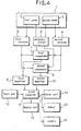
- Fig. 4 is a block diagram showing the construction of the gun detection system in accordance with the present invention.
- the gate 1 has a pair of panels 2 and 3 arranged opposite to each other, each of which includes transmission coils 15, auxiliary transmission coils 15', a reception coil 16, a differential space 17, zero point adjusters 18 and aluminum interrupters 19, embedded therein.
- At least one pair of transmission coils 15 are arranged in a predetermined area of each panel (along the edge of each panel) in a wound manner. These transmission coils 15 are applied respectively with a pair of transmission signals, which are opposite to each other in flow direction and phase such that the transmission coils 15 generate an electromagnetic field in one direction.
- the electromagnetic field is rotated around the transmission signals and then emitted in one direction at the moment that the transmission signals cross each other. At this time, the emitted electromagnetic field has an intensity amplified by twice that under the condition that it is rotated.
- the transmission coils 15 emit the electromagnetic field concentratedly toward a sensing space defined between the panels 2 and 3. Therefore, no electromagnetic field is emitted toward other areas than the sensing space such that there is no signal scattering resulting from interferences from other installations.
- At least one pair of auxiliary transmission coils 15' are arranged inside the transmission coils 15 and spaced apart therefrom at a predetermined distance to perform the same function as that of the transmission coils 15.
- the differential space 17 is defined by the predetermined distance between the transmission coils 15 and the auxiliary transmission coils 15' to secure an area for the generation of electromagnetic fields therebetween. This differential space 17 acts to attenuate an interference between the electromagnetic fields generated by the transmission coils 15 and auxiliary transmission coils 15' at maximum and prevent distortions of the generated electromagnetic fields. Also, the differential space 17 is determined within a range depending on the intensities of the electromagnetic fields generated by the transmission coils 15 and auxiliary transmission coils 15'.
- the reception coil 16 is arranged inside the auxiliary transmission coils 15' and adjacent thereto to receive the electromagnetic fields generated by the transmission coils 15 and auxiliary transmission coils 15' and electromagnetic fields scattered by a gun.
- This scattering is an electronic reaction of the generated electromagnetic fields to a metallic material of a gun when a person carrying the gun passes through the sensing space between the panels 2 and 3.
- the scattered electromagnetic fields have electromagnetic waves of shapes and intensities which differ according to the kind of metallic materials. For example, on the basis of the shapes and intensities of electromagnetic waves, determinations may be made as to whether a metallic material belongs to a gun and whether it is iron. In particular, the shapes and intensities of electromagnetic waves may be processed into data for use in calculation of the volume of a metallic material object.
- a pair of zero point adjusters 18 are formed inside and adjacent to the reception coil 16 and spaced apart from each other.
- Each of the zero pointer adjusters 18 has an internal space whose width is determined according to the width of the differential space 17 for the more accurate detection of the scattered electromagnetic fields without distortions of electromagnetic waves.
- the internal space of each of the zero point adjusters 18 preferably has a width proportional to that of the differential space 17 such that the reception coil 16 receives the scattered electromagnetic fields stably without an interference therebetween.
- a pair of aluminum interrupters 19 are attached to both sides of each of the panels 2 and 3 to interrupt external eddy electromagnetic fields.
- a scattered electromagnetic field generated therefrom may be sensed.
- the scattered electromagnetic field is generally considerably low in intensity.
- Each of the aluminum interrupters 19 preferably has a predetermined reference value higher than the intensities of electromagnetic fields scattered by external metallic materials. In this regard, the electromagnetic field scattered by the metallic body around the panels 2 and 3 is not received by the reception coil 16.
- the gun detection system comprises, as shown in Fig. 4, a detection gate 1 installed at the entrance/exit of a specific place.
- the detection gate 1 includes first and second panels 2 and 3 arranged opposite to each other for defining a sensing space therebetween.
- the first and second panels 2 and 3 are adapted to detect scattered electromagnetic fields and generate first and second sense signals having a phase difference therebetween in accordance with the detected results, respectively.
- An oscillation circuit 4 is provided to apply first and second transmission signals with opposite phases to transmission coils 15 in each of the first and second panels 2 to induce the transmission coils 15 to generate electromagnetic fields.
- a reception circuit is provided to receive the first and second sense signals from the first and second panels 2 and 3 and amplify the received sense signals by a predetermined gain.
- the gun detection system further comprises a comparison circuit for comparing the first and second sense signals received and amplified by the reception circuit with the first and second transmission signals from the oscillation circuit 4, respectively, and an amplification circuit for amplifying comparison data from the comparison circuit by a predetermined gain.
- the gun detection system further comprises a microcomputer 11, touch pad 12 and indication unit.
- the reception circuit includes a first receiver 5 for receiving and amplifying the first sense signal from the first panel 2, and a second receiver 6 for receiving and amplifying the second sense signal from the second panel 3.
- the comparison circuit functions to compare the amplified sense signals from the reception circuit with the transmission signals from the oscillation circuit 4 for determinations as to whether a sensed material is metal and whether it is iron.
- the comparison circuit includes a first comparator 7 for comparing the amplified first sense signal from the reception circuit with the first transmission signal from the oscillation circuit 4 for the determination as to whether the sensed material is metal, and a second comparator 8 for comparing the amplified second sense signal from the reception circuit with the second transmission signal from the oscillation circuit 4 for the determination as to whether the sensed material is iron.
- the amplification circuit includes a first amplifier 9 for amplifying output data from the first comparator 7, and a second amplifier 10 for amplifying output data from the second comparator 8.
- the microcomputer 11 is adapted to analyze the comparison data from the comparison circuit, amplified by the amplification circuit, according to a gun analysis algorithm, compare the analyzed data with pre-stored gun data and determine on the basis of the compared result whether the sensed material belongs to a gun.
- the microcomputer 11 preferably contains a memory (not shown) for storing electromagnetic field data relating to metals and their amounts of all types of existing guns. This memory also stores the above gun analysis algorithm, which compares the comparison data from the comparison circuit with the electromagnetic field data stored in the memory and determines the type and size of a gun in accordance with the compared result.
- the touch pad 12 is connected to the microcomputer 11 to input data regarding metals and guns to be detected from a user.
- the indication unit acts to provide an aural or visual indication of the result determined by the microcomputer 11 to the user.
- the indication unit includes a display unit 13 for providing the visual indication of the result determined by the microcomputer 11 to the user, an alarm unit 14 for providing the aural indication of the result determined by the microcomputer 11 to the user, an automatic dialer 23 for automatically dialing a preset telephone number to connect the result determined by the microcomputer 11 to the preset telephone number, and a camera 24 for shooting a person carrying a gun under control of the microcomputer 11.
- the camera, alarm unit and display unit act such that a person carrying a gun recognizes that his or her gun has been detected while passing through the entrance/exit of a specific place and such that other persons in the specific place recognize that the person who currently enters the specific place carries the gun. Further, the camera, alarm unit and display unit may induce an accomplice or accomplices inside or outside the specific place to abandon a crime. Moreover, these camera, alarm unit and display unit may inform persons outside the specific place of the occurrence of a crime inside the specific place.
- the display unit may preferably be installed over a counter of a store or in the entrance/exit of the store. In this case, the display unit may be installed together with a signboard displaying a message "Gun detection system is in operation in our store".
- the microcomputer outputs a control signal for an automatic dialing operation to the automatic dialer 23, which, in turn, automatically dials a preset telephone number of a police station or security company. This makes it possible to reduce the amount of time required for the moving in of the police when a crime occurs.
- a waiting-calling function may be set in order to enable a dialing operation for central office switching or calling.
- Example 1 9 + (waiting about 3 or 4 seconds) + designated telephone number
- Example 2 designated telephone number + (waiting about 3 or 4 seconds) + designated telephone number
- a "recall attempt function” is surely performed when the line is busy.
- a "next-dialing" function for sequentially dialing input telephone numbers may also be carried out.
- the transmission coils 15 and reception coil 16 are formed in each of the two panels 2 and 3 to define a sensing space between the panels 2 and 3 where no dead zone for sensing is present. Further, no electromagnetic field is emitted toward other areas than the sensing space such that there is no signal scattering resulting from interferences from other installations, thereby further improving a sensing accuracy of the sensing space.
- the comparators 7 and 8 compare sense signals received from the detection gate with transmission signals, respectively. If the sense signals are the same in level as the transmission signals, the comparators 7 and 8 generate signals indicative of the fact that no metal is sensed. In the case where the sense signals are not the same in level as the transmission signals, the first comparator 7 generates comparison data indicative of the fact that a sensed material is metal. In response to the comparison data from the first comparator 7, the microcomputer 11 analyzes the type of the metal and an article comprising the metal. Further, the second comparator 8 generates comparison data indicative of the fact that the sensed material is iron. In response to the comparison data from the second comparator 8, the microcomputer 11 analyzes the type and volume of the iron and, in turn, the type of a gun on the basis of the analyzed iron type and volume.
- the microcomputer 11 controls the alarm unit 14 and display unit 13 to aurally and visually inform the user that the person passing through the detection gate carries the gun of the analyzed type.
- the present invention provides a gun detection system which is capable of eliminating dead zones by sensing areas to more certainly detect guns of persons passing through a gate, thereby more certainly ensuring the safety of persons in airports, important government buildings, banks and the like. Further, the present gun detection system can make a more accurate distinction between gun metals and non-gun metals. This has the effect of protecting general persons with no gun.
Landscapes
- Physics & Mathematics (AREA)
- Life Sciences & Earth Sciences (AREA)
- Engineering & Computer Science (AREA)
- Remote Sensing (AREA)
- General Physics & Mathematics (AREA)
- Environmental & Geological Engineering (AREA)
- Geology (AREA)
- General Life Sciences & Earth Sciences (AREA)
- Electromagnetism (AREA)
- Geophysics (AREA)
- Geophysics And Detection Of Objects (AREA)
- Aiming, Guidance, Guns With A Light Source, Armor, Camouflage, And Targets (AREA)
- Optical Radar Systems And Details Thereof (AREA)
- Radar Systems Or Details Thereof (AREA)
- Investigating Or Analysing Materials By Optical Means (AREA)
- Investigating Or Analyzing Materials By The Use Of Ultrasonic Waves (AREA)
Applications Claiming Priority (2)
| Application Number | Priority Date | Filing Date | Title |
|---|---|---|---|
| KR10-2000-0083864A KR100429471B1 (ko) | 2000-12-28 | 2000-12-28 | 총기류검색시스템 |
| KR2000083864 | 2000-12-28 |
Publications (3)
| Publication Number | Publication Date |
|---|---|
| EP1219976A2 EP1219976A2 (en) | 2002-07-03 |
| EP1219976A3 EP1219976A3 (en) | 2003-07-09 |
| EP1219976B1 true EP1219976B1 (en) | 2005-10-26 |
Family
ID=36686688
Family Applications (1)
| Application Number | Title | Priority Date | Filing Date |
|---|---|---|---|
| EP01110426A Expired - Lifetime EP1219976B1 (en) | 2000-12-28 | 2001-04-27 | Gun detection system |
Country Status (5)
| Country | Link |
|---|---|
| EP (1) | EP1219976B1 (ko) |
| KR (1) | KR100429471B1 (ko) |
| CN (1) | CN1165761C (ko) |
| AT (1) | ATE308058T1 (ko) |
| DE (1) | DE60114355T2 (ko) |
Families Citing this family (10)
| Publication number | Priority date | Publication date | Assignee | Title |
|---|---|---|---|---|
| EP1750148A1 (en) * | 2005-08-04 | 2007-02-07 | Giovanni Manneschi | Metal detector presenting high performance |
| ES2476025T3 (es) | 2005-08-04 | 2014-07-11 | Alessandro Manneschi | Detector de metales |
| EP1750149B1 (en) * | 2005-08-04 | 2017-05-10 | M. Alessandro Manneschi | Metal detector |
| KR100967564B1 (ko) * | 2008-03-17 | 2010-07-05 | (주)대동하이텍 | 전자기파 차폐판을 구비한 문형 금속 탐지기 |
| TWI416950B (zh) * | 2009-10-07 | 2013-11-21 | Ind Tech Res Inst | 監控方法及其系統 |
| CN101881839B (zh) * | 2010-05-18 | 2012-11-07 | 漳州市玉山电子制造有限公司 | 一种简易快装式金属探测门 |
| TWI530703B (zh) * | 2011-02-23 | 2016-04-21 | 宏碁股份有限公司 | 電子裝置及其定位方法 |
| CN105866846A (zh) * | 2016-03-25 | 2016-08-17 | 东莞市华盾电子科技有限公司 | 一种手持式铁制武器探测器 |
| HUE052495T2 (hu) * | 2016-07-26 | 2021-04-28 | Alert Systems Aps | Lopásgátló rendszer és eljárás |
| CN108828591A (zh) * | 2018-07-04 | 2018-11-16 | 中国矿业大学(北京) | 一种便携式雷达探测设备及系统 |
Family Cites Families (9)
| Publication number | Priority date | Publication date | Assignee | Title |
|---|---|---|---|---|
| JPS496973B1 (ko) * | 1969-03-03 | 1974-02-18 | ||
| US3758849A (en) * | 1972-03-31 | 1973-09-11 | Sperry Rand Corp | Metal detector system having identical balanced field coil system on opposite sides of a detection zone |
| US4634975A (en) * | 1984-09-17 | 1987-01-06 | Progressive Dynamics, Inc. | Method and apparatus for producing electromagnetic surveillance fields |
| EP0222028B1 (de) * | 1985-11-02 | 1988-12-28 | Vallon GmbH | Metalldetektor zur Erkennung von metallischen Gegenständen |
| US4906973A (en) * | 1988-04-29 | 1990-03-06 | White's Electronics, Inc. | Walk-through metal detector |
| US5397986A (en) * | 1991-11-01 | 1995-03-14 | Federal Labs Systems Lp | Metal detector system having multiple, adjustable transmitter and receiver antennas |
| KR200148230Y1 (ko) * | 1997-05-29 | 1999-06-15 | 복 순 김 | 게이트형 금속탐지기 |
| KR200170058Y1 (ko) * | 1997-06-24 | 2000-03-02 | 정창구 | 금속탐지기 |
| KR100228251B1 (ko) * | 1997-12-20 | 1999-11-01 | 박병용 | 권총류 탐지시스템 |
-
2000
- 2000-12-28 KR KR10-2000-0083864A patent/KR100429471B1/ko not_active IP Right Cessation
-
2001
- 2001-04-27 DE DE60114355T patent/DE60114355T2/de not_active Expired - Fee Related
- 2001-04-27 AT AT01110426T patent/ATE308058T1/de not_active IP Right Cessation
- 2001-04-27 EP EP01110426A patent/EP1219976B1/en not_active Expired - Lifetime
- 2001-08-01 CN CNB011203412A patent/CN1165761C/zh not_active Expired - Fee Related
Also Published As
| Publication number | Publication date |
|---|---|
| CN1165761C (zh) | 2004-09-08 |
| KR20020054695A (ko) | 2002-07-08 |
| DE60114355D1 (de) | 2005-12-01 |
| EP1219976A2 (en) | 2002-07-03 |
| DE60114355T2 (de) | 2006-08-03 |
| KR100429471B1 (ko) | 2004-05-03 |
| CN1361421A (zh) | 2002-07-31 |
| ATE308058T1 (de) | 2005-11-15 |
| EP1219976A3 (en) | 2003-07-09 |
Similar Documents
| Publication | Publication Date | Title |
|---|---|---|
| US5121105A (en) | Metal detector | |
| EP1219976B1 (en) | Gun detection system | |
| CN105842739B (zh) | 通过式特定金属探测门 | |
| KR100650628B1 (ko) | 총기류 검색시스템의 구동방법 | |
| US10884153B2 (en) | Magnetic detectors | |
| AU4281899A (en) | Apparatus for detecting metals | |
| US20100315080A1 (en) | metal detector | |
| EP2567266B1 (en) | Method and system for sliding door pattern cancellation in metal detection | |
| KR20110044783A (ko) | 통합된 방향성 인원 계수 시스템을 갖는 금속 탐지 시스템 | |
| KR100465487B1 (ko) | 도어 고정 장치를 구비한 총기류 검색 시스템 | |
| US6900727B2 (en) | Weapon detector system | |
| EP0736850B1 (en) | Method for preventing shoplifting and electronic theft detection system | |
| KR100967564B1 (ko) | 전자기파 차폐판을 구비한 문형 금속 탐지기 | |
| US20020027509A1 (en) | Object detection system | |
| AU2019294550A1 (en) | Portable detection system comprising magnetostatic sensors | |
| AU2019294551A1 (en) | Portable detection system comprising magnetostatic sensors | |
| CN112703430A (zh) | 用于探测金属和磁化目标物体的组合式探测器 | |
| US6686846B1 (en) | Detachable entrance and exit gate with a combined commodity burglarproof and weapon detecting system | |
| KR100650630B1 (ko) | 총기류 검색시스템의 총기 검출 방법 | |
| KR100650627B1 (ko) | 총기류 검색시스템의 총기 검출 방법 | |
| CN112639535A (zh) | 包括静磁传感器的便携式检测系统 | |
| KR100650631B1 (ko) | 총기류 검색시스템의 구동방법 | |
| RU2782706C2 (ru) | Передвижная система обнаружения, содержащая магнитостатические датчики | |
| KR20000034631A (ko) | 전자식 금전 등록기를 이용한 매장 보안 장치 |
Legal Events
| Date | Code | Title | Description |
|---|---|---|---|
| PUAI | Public reference made under article 153(3) epc to a published international application that has entered the european phase |
Free format text: ORIGINAL CODE: 0009012 |
|
| AK | Designated contracting states |
Kind code of ref document: A2 Designated state(s): AT BE CH CY DE DK ES FI FR GB GR IE IT LI LU MC NL PT SE TR |
|
| AX | Request for extension of the european patent |
Free format text: AL;LT;LV;MK;RO;SI |
|
| PUAL | Search report despatched |
Free format text: ORIGINAL CODE: 0009013 |
|
| AK | Designated contracting states |
Designated state(s): AT BE CH CY DE DK ES FI FR GB GR IE IT LI LU MC NL PT SE TR |
|
| AX | Request for extension of the european patent |
Extension state: AL LT LV MK RO SI |
|
| RIC1 | Information provided on ipc code assigned before grant |
Ipc: 7G 01V 3/10 A Ipc: 7G 08B 13/24 B |
|
| 17P | Request for examination filed |
Effective date: 20031030 |
|
| AKX | Designation fees paid |
Designated state(s): AT BE CH CY DE DK ES FI FR GB GR IE IT LI LU MC NL PT SE TR |
|
| 17Q | First examination report despatched |
Effective date: 20040903 |
|
| RAP1 | Party data changed (applicant data changed or rights of an application transferred) |
Owner name: BANGSAN TECHNOLOGIES INC. |
|
| GRAP | Despatch of communication of intention to grant a patent |
Free format text: ORIGINAL CODE: EPIDOSNIGR1 |
|
| GRAS | Grant fee paid |
Free format text: ORIGINAL CODE: EPIDOSNIGR3 |
|
| GRAA | (expected) grant |
Free format text: ORIGINAL CODE: 0009210 |
|
| AK | Designated contracting states |
Kind code of ref document: B1 Designated state(s): AT BE CH CY DE DK ES FI FR GB GR IE IT LI LU MC NL PT SE TR |
|
| PG25 | Lapsed in a contracting state [announced via postgrant information from national office to epo] |
Ref country code: FI Free format text: LAPSE BECAUSE OF FAILURE TO SUBMIT A TRANSLATION OF THE DESCRIPTION OR TO PAY THE FEE WITHIN THE PRESCRIBED TIME-LIMIT Effective date: 20051026 Ref country code: NL Free format text: LAPSE BECAUSE OF FAILURE TO SUBMIT A TRANSLATION OF THE DESCRIPTION OR TO PAY THE FEE WITHIN THE PRESCRIBED TIME-LIMIT Effective date: 20051026 Ref country code: LI Free format text: LAPSE BECAUSE OF FAILURE TO SUBMIT A TRANSLATION OF THE DESCRIPTION OR TO PAY THE FEE WITHIN THE PRESCRIBED TIME-LIMIT Effective date: 20051026 Ref country code: AT Free format text: LAPSE BECAUSE OF FAILURE TO SUBMIT A TRANSLATION OF THE DESCRIPTION OR TO PAY THE FEE WITHIN THE PRESCRIBED TIME-LIMIT Effective date: 20051026 Ref country code: CH Free format text: LAPSE BECAUSE OF FAILURE TO SUBMIT A TRANSLATION OF THE DESCRIPTION OR TO PAY THE FEE WITHIN THE PRESCRIBED TIME-LIMIT Effective date: 20051026 Ref country code: BE Free format text: LAPSE BECAUSE OF FAILURE TO SUBMIT A TRANSLATION OF THE DESCRIPTION OR TO PAY THE FEE WITHIN THE PRESCRIBED TIME-LIMIT Effective date: 20051026 |
|
| REG | Reference to a national code |
Ref country code: GB Ref legal event code: FG4D |
|
| REG | Reference to a national code |
Ref country code: CH Ref legal event code: EP |
|
| REG | Reference to a national code |
Ref country code: IE Ref legal event code: FG4D |
|
| REF | Corresponds to: |
Ref document number: 60114355 Country of ref document: DE Date of ref document: 20051201 Kind code of ref document: P |
|
| PG25 | Lapsed in a contracting state [announced via postgrant information from national office to epo] |
Ref country code: SE Free format text: LAPSE BECAUSE OF FAILURE TO SUBMIT A TRANSLATION OF THE DESCRIPTION OR TO PAY THE FEE WITHIN THE PRESCRIBED TIME-LIMIT Effective date: 20060126 Ref country code: DK Free format text: LAPSE BECAUSE OF FAILURE TO SUBMIT A TRANSLATION OF THE DESCRIPTION OR TO PAY THE FEE WITHIN THE PRESCRIBED TIME-LIMIT Effective date: 20060126 Ref country code: GR Free format text: LAPSE BECAUSE OF FAILURE TO SUBMIT A TRANSLATION OF THE DESCRIPTION OR TO PAY THE FEE WITHIN THE PRESCRIBED TIME-LIMIT Effective date: 20060126 |
|
| PG25 | Lapsed in a contracting state [announced via postgrant information from national office to epo] |
Ref country code: ES Free format text: LAPSE BECAUSE OF FAILURE TO SUBMIT A TRANSLATION OF THE DESCRIPTION OR TO PAY THE FEE WITHIN THE PRESCRIBED TIME-LIMIT Effective date: 20060206 |
|
| PG25 | Lapsed in a contracting state [announced via postgrant information from national office to epo] |
Ref country code: PT Free format text: LAPSE BECAUSE OF FAILURE TO SUBMIT A TRANSLATION OF THE DESCRIPTION OR TO PAY THE FEE WITHIN THE PRESCRIBED TIME-LIMIT Effective date: 20060327 |
|
| NLV1 | Nl: lapsed or annulled due to failure to fulfill the requirements of art. 29p and 29m of the patents act | ||
| PG25 | Lapsed in a contracting state [announced via postgrant information from national office to epo] |
Ref country code: IE Free format text: LAPSE BECAUSE OF NON-PAYMENT OF DUE FEES Effective date: 20060427 |
|
| PG25 | Lapsed in a contracting state [announced via postgrant information from national office to epo] |
Ref country code: MC Free format text: LAPSE BECAUSE OF NON-PAYMENT OF DUE FEES Effective date: 20060430 |
|
| REG | Reference to a national code |
Ref country code: CH Ref legal event code: PL |
|
| ET | Fr: translation filed | ||
| PLBE | No opposition filed within time limit |
Free format text: ORIGINAL CODE: 0009261 |
|
| STAA | Information on the status of an ep patent application or granted ep patent |
Free format text: STATUS: NO OPPOSITION FILED WITHIN TIME LIMIT |
|
| 26N | No opposition filed |
Effective date: 20060727 |
|
| REG | Reference to a national code |
Ref country code: IE Ref legal event code: MM4A |
|
| REG | Reference to a national code |
Ref country code: GB Ref legal event code: 732E |
|
| PG25 | Lapsed in a contracting state [announced via postgrant information from national office to epo] |
Ref country code: LU Free format text: LAPSE BECAUSE OF NON-PAYMENT OF DUE FEES Effective date: 20060427 |
|
| PGFP | Annual fee paid to national office [announced via postgrant information from national office to epo] |
Ref country code: TR Payment date: 20080425 Year of fee payment: 8 Ref country code: IT Payment date: 20080428 Year of fee payment: 8 |
|
| PG25 | Lapsed in a contracting state [announced via postgrant information from national office to epo] |
Ref country code: CY Free format text: LAPSE BECAUSE OF FAILURE TO SUBMIT A TRANSLATION OF THE DESCRIPTION OR TO PAY THE FEE WITHIN THE PRESCRIBED TIME-LIMIT Effective date: 20051026 |
|
| PGFP | Annual fee paid to national office [announced via postgrant information from national office to epo] |
Ref country code: GB Payment date: 20080424 Year of fee payment: 8 |
|
| PGFP | Annual fee paid to national office [announced via postgrant information from national office to epo] |
Ref country code: DE Payment date: 20090430 Year of fee payment: 9 |
|
| GBPC | Gb: european patent ceased through non-payment of renewal fee |
Effective date: 20090427 |
|
| REG | Reference to a national code |
Ref country code: FR Ref legal event code: ST Effective date: 20091231 |
|
| PG25 | Lapsed in a contracting state [announced via postgrant information from national office to epo] |
Ref country code: FR Free format text: LAPSE BECAUSE OF NON-PAYMENT OF DUE FEES Effective date: 20091222 Ref country code: GB Free format text: LAPSE BECAUSE OF NON-PAYMENT OF DUE FEES Effective date: 20090427 |
|
| PGFP | Annual fee paid to national office [announced via postgrant information from national office to epo] |
Ref country code: FR Payment date: 20080429 Year of fee payment: 8 |
|
| PG25 | Lapsed in a contracting state [announced via postgrant information from national office to epo] |
Ref country code: DE Free format text: LAPSE BECAUSE OF NON-PAYMENT OF DUE FEES Effective date: 20101103 |
|
| PG25 | Lapsed in a contracting state [announced via postgrant information from national office to epo] |
Ref country code: IT Free format text: LAPSE BECAUSE OF NON-PAYMENT OF DUE FEES Effective date: 20090427 |
|
| PG25 | Lapsed in a contracting state [announced via postgrant information from national office to epo] |
Ref country code: TR Free format text: LAPSE BECAUSE OF NON-PAYMENT OF DUE FEES Effective date: 20090427 |