EP1219853A2 - Method of producing vibration-isolating bushing - Google Patents
Method of producing vibration-isolating bushing Download PDFInfo
- Publication number
- EP1219853A2 EP1219853A2 EP01125543A EP01125543A EP1219853A2 EP 1219853 A2 EP1219853 A2 EP 1219853A2 EP 01125543 A EP01125543 A EP 01125543A EP 01125543 A EP01125543 A EP 01125543A EP 1219853 A2 EP1219853 A2 EP 1219853A2
- Authority
- EP
- European Patent Office
- Prior art keywords
- inner cylinder
- upsetting
- jig
- edge surface
- vibration
- Prior art date
- Legal status (The legal status is an assumption and is not a legal conclusion. Google has not performed a legal analysis and makes no representation as to the accuracy of the status listed.)
- Granted
Links
Images


Classifications
-
- B—PERFORMING OPERATIONS; TRANSPORTING
- B21—MECHANICAL METAL-WORKING WITHOUT ESSENTIALLY REMOVING MATERIAL; PUNCHING METAL
- B21K—MAKING FORGED OR PRESSED METAL PRODUCTS, e.g. HORSE-SHOES, RIVETS, BOLTS OR WHEELS
- B21K21/00—Making hollow articles not covered by a single preceding sub-group
- B21K21/12—Shaping end portions of hollow articles
-
- B—PERFORMING OPERATIONS; TRANSPORTING
- B21—MECHANICAL METAL-WORKING WITHOUT ESSENTIALLY REMOVING MATERIAL; PUNCHING METAL
- B21J—FORGING; HAMMERING; PRESSING METAL; RIVETING; FORGE FURNACES
- B21J9/00—Forging presses
- B21J9/02—Special design or construction
- B21J9/025—Special design or construction with rolling or wobbling dies
-
- F—MECHANICAL ENGINEERING; LIGHTING; HEATING; WEAPONS; BLASTING
- F16—ENGINEERING ELEMENTS AND UNITS; GENERAL MEASURES FOR PRODUCING AND MAINTAINING EFFECTIVE FUNCTIONING OF MACHINES OR INSTALLATIONS; THERMAL INSULATION IN GENERAL
- F16F—SPRINGS; SHOCK-ABSORBERS; MEANS FOR DAMPING VIBRATION
- F16F1/00—Springs
- F16F1/36—Springs made of rubber or other material having high internal friction, e.g. thermoplastic elastomers
- F16F1/38—Springs made of rubber or other material having high internal friction, e.g. thermoplastic elastomers with a sleeve of elastic material between a rigid outer sleeve and a rigid inner sleeve or pin, i.e. bushing-type
- F16F1/3842—Method of assembly, production or treatment; Mounting thereof
-
- F—MECHANICAL ENGINEERING; LIGHTING; HEATING; WEAPONS; BLASTING
- F16—ENGINEERING ELEMENTS AND UNITS; GENERAL MEASURES FOR PRODUCING AND MAINTAINING EFFECTIVE FUNCTIONING OF MACHINES OR INSTALLATIONS; THERMAL INSULATION IN GENERAL
- F16F—SPRINGS; SHOCK-ABSORBERS; MEANS FOR DAMPING VIBRATION
- F16F2226/00—Manufacturing; Treatments
- F16F2226/04—Assembly or fixing methods; methods to form or fashion parts
-
- Y—GENERAL TAGGING OF NEW TECHNOLOGICAL DEVELOPMENTS; GENERAL TAGGING OF CROSS-SECTIONAL TECHNOLOGIES SPANNING OVER SEVERAL SECTIONS OF THE IPC; TECHNICAL SUBJECTS COVERED BY FORMER USPC CROSS-REFERENCE ART COLLECTIONS [XRACs] AND DIGESTS
- Y10—TECHNICAL SUBJECTS COVERED BY FORMER USPC
- Y10T—TECHNICAL SUBJECTS COVERED BY FORMER US CLASSIFICATION
- Y10T29/00—Metal working
- Y10T29/49—Method of mechanical manufacture
- Y10T29/49636—Process for making bearing or component thereof
- Y10T29/49643—Rotary bearing
- Y10T29/49647—Plain bearing
- Y10T29/49668—Sleeve or bushing making
Definitions
- This invention relates to a method of producing a vibration-isolating bushing which is mainly used by being assembled into an automobile suspsension system or the like.
- a cylindrical vibration-isolating bushing is generally used at a coupling part between the vehicle body and the suspension, namely the coupling part between a lower arm or other arm for supporting wheels and a vehicle body side member such as a frame with a view to vibration damping and shock absorbing.
- the cylindrical vibration-isolating bushing can also be used for an engine mount supporting or bearing the engine in a vibration-proof fashion.
- a conventional vibration-isolating bushing is, for example, known in the art as shown in Fig. 8, wherein the bushing 100 is made up of an inner cylinder 101 and an outer cylinder 102 both made of metal and disposed concentrically, and a rubber elastomer 103 interposed between the both.
- a shaft component 104 is inserted in the inner cylinder 101, which is in turn fastened to supporting components 105 such as brackets pinching it from both sides thereby to fix the inner cylinder.
- the outer cylinder 102 is inserted in an attachment hole 107 of another supporting component 106 to be fixed to it.
- the inner cylinder 101 of the vibration-isolating bushing 100 is pinched and held at both extremities thereof by the supporting components 105 in this way if the area of the edge surface 108 of the inner cylinder 101 is small, the surface pressure of the edge surface subjected to an axial force by the fastening becomes higher, with the result that the supporting members 105 such as brackets press formed by a plate material subside and a problem of bolts releasing is caused.
- a small-diameter portion 111 inboard of the extremities 109 assumes an undercut shape relative to the mold releasing in the axial direction, so that edge surfaces 110 of the rubber elastomer 103 cannot be set at two dots-dash line positions 112 considering the mold releasing after molding. That's why the areas of the edge surfaces 110 of the rubber elastomer 103 are too small to secure a sufficient free length to elastic deformation.
- JP Patent Publication 1993-200438 A1 discloses, as shown in Fig. 10, upsetting the extremities 109 of the inner cylinder 101 by cold plastic working by the use of an upsetting jig 120 after vulcanization molding of the rubber elastomer 103 thereby enlarging the edge surfaces 108.
- an upsetting jig 120 having at its top central surface a projection 12 is used and the edge surface 108 is enlarged by pressing the upsetting jig 120 onto the edge surface 108 of the inner cylinder while causing it to gyrate on a conical orbit centering the axis 122 of the inner cylinder 101 thereby enlarging the edge surface 108 as shown in Fig. 11.
- the extremity 109 of the inner cylinder 101 is enlarged in inside diameter d 0 as well as outside diameter D 0 as shown in Fig. 11, so that the area of the edge surface 108 of the inner cylinder is narrowed by the increment in inside diameter d 0 and hence it is difficult to secure an area enough to reduce the surface area against the axial force.
- a principal object of this invention is to provide a method of producing a vibration-isolating bushing with which it is possible to secure a much larger areas for each edge surface of the inner cylinder in upsetting the extremities of the inner cylinder by cold plastic working after vulcanization molding of the rubber elastomer than conventional method.
- This invention provides a method of producing a vibration-isolating bushing comprising securing a rubber elastomer to an outer circumference of an inner cylinder by vulcanization molding and is characterized in that in upsetting axial extremities of the inner cylinder by cold plastic working after vulcanization molding, an upsetting jig whose top surface is substantially flat is used to as an upsetting jig for pressing onto each edge surface of the inner cylinder and the top surface of the upsetting jig is pressed onto the edge surface of the inner cylinder while causing it to gyrate on a conical orbit centering the axis of the inner cylinder, thereby enlarging the edge surface of the inner cylinder.
- a constraint wall for surrounding the outer circumference of each of the extremities of the inner cylinder to be upset may be vertically arranged at the peripheral portion of the top surface of the upsetting jig, thereby inhibiting the extremities from being enlarged beyond a predetermined diameter.
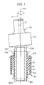
- Figs. 1 to 3 are concerned with a first embodiment of this invention;
- Fig. 1 is a sectional view of a vibration-isolating bushing 10 upon upsetting working
- Fig. 2 is an elevational view of an upsetting jig 30 used for the upsetting working
- Fig. 3 is a sectional view of the vibration-isolating bushing 10 thus obtained.
- the vibration-isolating bushing 10 is made up of an inner cylinder 12 and an outer cylinder 14 concentrically arranged in a spaced relation and made of a metal tube such as iron, steel, aluminum or alloy thereof and a rubber elastomer 16 interposed between the inner and outer cylinders 12, 14 by vulcanization molding to bond integrally both cylinders.
- the rubber elastomer 16 is secured to an outer circumferential surface of the inner cylinder 12 and an inner circumferential sruface of the outer cylinder 14 by vulcanization adhesion means.
- the inner cylinder 12 is somewhat longer than the outer cylinder 14 and the rubber elastomer 16, and upset at both extremities 18a, 18b to form enlarged edge surfaces 20a, 20b as compared to the edge surface with a normal wall thickness.
- the rubber elastomer 16 is molded by vulcanization between the inner cylinder 12 and the outer cylinder 14 in a mold cavity (not shown). At that time, as the inner cylinder 12, as shown in Fig. 1, a straight tube, which is not subjected to upsetting working at both extremities 18a, 18b is used by cutting in a length a little longer than the final product, taking account of the upsetting working of the extremities.
- the vulcanization molded body is subjected to a cold plastic working that imparts a plastic deformation to the the axial extremities of the inner cylinder 12, thereby upsetting the extremities.
- a working jig for butt pressing onto the edge surfaces 20a, 20b of the inner cylinder 12 an upsetting jig having a nearly flat top edge surface 32 as shown in Fig. 1 is used.
- the top edge surface 32 of the upsetting jig 30 is pressed onto the edge surfaces 20a, 20b of the inner cylinder 12 thereby enlarging the edge surfaces of the inner cylinder 12.
- the upsetting jig 30 is provided with a large-diameter columnar portion 34 at its lower end and an attachment portion 36 at its upper end so that the attachment portion 36 may be fitted to a revolution device not shown.
- the top edge surface 32 of the upsetting jig 30, which is the underside of the columnar portion 34, is formed in a nearly flat conical plane slightly projecting forwardly to the pressing direction.
- the tilting angle ⁇ of the conical surface (edge surface) 32 is usually set to be 0 ⁇ 10°.
- the diameter of the columnar portion 34 is set larger than the outside diameter of the inner cylinder 12 as illustrated in Fig. 1.
- the upsetting jig 30 is fitted to the revolution device to be tilted so that the axis center x1 makes a definite angle of ⁇ relative to the axis x0 of the inner cylinder 12. And the upsetting jig 30 presses the edge surfaces 20a, 20b of the inner cylinder 12 while conducting a gyration movement so that the axis x1 may move on a conical surface centering the exis x0 by the operation of the revolution device.
- the angle ⁇ is set so that the conical top edge surface 32 of the upsetting jig 30 may be nearly in parallel with the edge surfaces 20a, 20b of the inner cylinder 12, and accordingly, set to be nearly the same as the tilting angle ⁇ of the top edge surface 32.
- the upsetting working of the inner cylinder 12 by means of the upsetting jig 30 is started first from the one extremity, for example, the extremity 18a to be subjected to a larger plastic deformation according to the procedure described above, and thereafter conducted similarly with the other extremity 18b to be subjected to a smaller plastic deformation after inverting the vulcanization molded body upside down.
- the vibration-isolating bushing 10 thus obtained is, as shown in Fig. 3, fixed with the outer cylinder 14 press fitted into an attachment hole 42 of a support member 40 such as suspension arms or the like and with the inner cylinder 12 pierced into a shaft member 44 on the other support side and fastened with support members 46 such as brackets in the state pinched from both sides.
- the extremities 18a, 18b of the inner cylinder 12 are subjected to upsetting working to enlarge the edge surfaces 20a, 20b it is possible to secure such an area that can reduce the surface pressure against the axial force by fastening with the support members 44 without the necessity of increasing the wall thickness of the inner cylinder 12 and besides, at a light weight and a chiep cost.
- the upsetting jig 30 having no projection, but a flat surface at the top edge surface 32 is used, it is possible to upset the outside diameter D only so as not to change the inside diameter d and hence it is possible to secure a sufficiently large area of the edge surface 20 of the inner cylinder 12.
- Fig. 4 is a sectional view of a vibration-isolating bushing 10 relating to a second embodiment of this invention when subjected to upsetting working;
- Fig. 5 is an elevational view of an upsetting jig 30 used for the upsetting working;
- Fig. 6 is a sectional view of the vibration-isolating bushing 10 obtained by the upsetting working;
- Fig. 7 is an enlarged sectional view showing essential parts when the upsetting working is finished.
- This second embodiment is different from the first embodiment in the shape of the upsetting jig 30 for working extremities of the inner cylinder 12. That is, in this embodiment, a constraint wall 38 for surrounding the whole outer peripheries of the extremities 18a, 18b of the inner cylinder 11 to be upset is disposed vertically in the peripheral portion of the top edge surface 32 assuming a nearly flat conical surface of the upsetting jig 30 so as to restrain the extremities 18a, 18b of the inner cylinder from being upset more than a required diameter.
- the constraint wall 38 is formed to project downwardly from the periphery of the top edge surface 32 of the columnar portion 34, namely forwardly in the pressing direction and its inside is formed to be in a nearly flat conical plane.
- the wall surface at the inner periphery side of the constraint wall 38 is tilted outwardly by a required angle ⁇ , and the angle ⁇ is set to be nearly the same as the tilting angle of the top edge surface 32 so that the wall surface is substantially vertical to the extremity 20 of the inner cylinder upon upsetting working.
- the width W of the conical, practically flat surface inside the constraint wall 38 is set appropriately depending on a desired dimension of the outside diameter D of the extremity 18 of the inner cylinder to be upset.
- the outer periphery of the extremity 18a of the inner cylinder 12 is, as shown in Fig. 7, enlarged in diameter up to the constraint wall 38, from where the extremity is no longer able to further enlarge on the outside diameter side, so that a plastic deformation occurs by that amount toward the inside diameter side.
- a plastic deformation occurs by that amount toward the inside diameter side.
- the upsetting working is applied to tbe both extremities 18a, 18b of th einner cylinder 12, but this invention is not limited to these examples, but only one extremity may be upset.
- the description above was made on the vibration-isolating bushing 10 of the type that the rubber elastomer 16 is interposed between the inner cylinder 12 and the outer cylinder 14 to be press fitted in the attachment hole 42 of the support member 40 and secured to both cylinders, but it is possible to likewise construct the extremity 18 of the inner cylinder 12 also in another type of vibration-isolating bushing that is used by press fitting the rubber elastomer 16, secured only to the outer circumference of the inner cylinder 12 by vulcanization molding, into the attachment hole of the other support member.
- a method of producing a vibration-isolating bushing with which it is possible to secure a larger area of the edge surface of an inner cylinder than in the prior art method In upsetting one extremity (18a) of the inner cylinder (12) by cold plastic working, after a rubber elastomer (16) is secured to the outer circumference of the inner cylinder by vulcanization molding, as a jig for pressing onto the edge surface of the inner cylinder, an upsetting jig (30) whose top surface (32) is flat is used and the top surface (32) of the jig (30) is pressed onto the edge surface (20a) of the inner cylinder (12) while causing the jig to gyrate on a conical orbit centering the axis (x0) of the inner cylinder (12), whereby the outside diameter only of the extremity (18a) is enlarged while suppressing the enlarging of the inside diameter.
Landscapes
- Engineering & Computer Science (AREA)
- Mechanical Engineering (AREA)
- General Engineering & Computer Science (AREA)
- Manufacturing & Machinery (AREA)
- Springs (AREA)
- Forging (AREA)
Abstract
Description
Claims (3)
- A method of producing a vibration-insulating bushing comprised of a rubber elastomer secured on an outer circumference of an inner cylinder by vulcanization molding which comprises, after the vulcanization molding of the rubber elastomer, submitting an axial extremity of the inner cylinder to upsetting by cold plastic working,
which method is characterized by using, as an upsetting jig for pressing on an edge surface of the extremity of the inner cylinder, a jig (30) whose top surface (32) is substantially flat and by pressing the top surface of the upsetting jig onto the edge surface (20) of the inner cylinder (12) while causing the jig to gyrate on a conical orbit centering the axis (x0) of the inner cylinder (12), thereby enlarging the edge surface of the inner cylinder. - The method of producing a vibration-insulating bushing as set forth in claim 1, which is characterized by using an upsetting jig (30) whose top surface (32) has a slightly bulged conical surface and by tilting the upsetting jig relative to the axis (x0) of the inner cylinder (12) so that the conical surface (32) may be generally in parallel with the edge surface (20) of the inner cylinder (12).
- The method of producing a vibration-insulating bushing as set forth in claim 1 or 2, which is characterized in that a constraint wall (38) for surrounding an outer circumference of the extremity (18) of the inner cylinder (12) to be upset is arranged vertically in a peripheral margin of the top surface (32) of the upsetting jig (30), thereby restraining the extremity of the inner cylinder from being upset beyond a predetermined diameter.
Applications Claiming Priority (2)
| Application Number | Priority Date | Filing Date | Title |
|---|---|---|---|
| JP2000393527 | 2000-12-25 | ||
| JP2000393527A JP2002188671A (en) | 2000-12-25 | 2000-12-25 | Manufacturing method of anti-vibration bush |
Publications (3)
| Publication Number | Publication Date |
|---|---|
| EP1219853A2 true EP1219853A2 (en) | 2002-07-03 |
| EP1219853A3 EP1219853A3 (en) | 2003-07-16 |
| EP1219853B1 EP1219853B1 (en) | 2004-12-29 |
Family
ID=18859313
Family Applications (1)
| Application Number | Title | Priority Date | Filing Date |
|---|---|---|---|
| EP01125543A Expired - Lifetime EP1219853B1 (en) | 2000-12-25 | 2001-10-25 | Method of producing vibration-isolating bushing |
Country Status (4)
| Country | Link |
|---|---|
| US (1) | US6626020B2 (en) |
| EP (1) | EP1219853B1 (en) |
| JP (1) | JP2002188671A (en) |
| DE (1) | DE60108061T2 (en) |
Cited By (3)
| Publication number | Priority date | Publication date | Assignee | Title |
|---|---|---|---|---|
| EP1563927A1 (en) * | 2004-02-13 | 2005-08-17 | Michelin AVS S.A.S. | Method of forming the end region of a rigid sleeve, forming tool, and elastic articulation |
| FR2935769A1 (en) * | 2008-09-10 | 2010-03-12 | Renault Sas | ELASTIC ARTICULATION OF SUSPENSION OF A MOTOR VEHICLE AND STRUCTURE OF A MOTOR VEHICLE COMPRISING SUCH ARTICULATION |
| EP3601838A1 (en) * | 2017-03-22 | 2020-02-05 | Vibracoustic GmbH | Core for an elastic bearing, elastic bearing comprising such a core, and a method for producing such a core |
Families Citing this family (10)
| Publication number | Priority date | Publication date | Assignee | Title |
|---|---|---|---|---|
| WO2002085552A1 (en) * | 2001-04-19 | 2002-10-31 | Toyo Tire & Rubber Co., Ltd. | Method of working end part of metallic tube body and metallic tube body, and method of manufacturing vibrationproof bush using the working method and vibrationproof bush |
| WO2004065035A1 (en) * | 2003-01-20 | 2004-08-05 | Toyo Tire Rubber Co.,Ltd. | Method of processing end of sleeve, sleeve processed by this method, method of producing anti-vibration bushing, anti-vibration bushing, and pressing tool |
| JP5026846B2 (en) * | 2006-04-28 | 2012-09-19 | 東海ゴム工業株式会社 | Rubber member with aluminum metal product and manufacturing method thereof |
| AU311044S (en) * | 2006-09-22 | 2006-10-30 | Cablestik Pty Ltd | Attachment housing for tow ball |
| US20090046973A1 (en) * | 2007-08-16 | 2009-02-19 | Gm Global Technology Operations, Inc. | Bearing retention method and apparatus |
| JP2010071459A (en) * | 2008-09-22 | 2010-04-02 | Somic Ishikawa Inc | Ball joint and method for manufacturing the same |
| US8827017B2 (en) * | 2012-03-30 | 2014-09-09 | Thermo King Corporation | Vehicle or environment-controlled unit having a multiphase alternator with a protected high-voltage bus |
| JP2017096354A (en) | 2015-11-20 | 2017-06-01 | 東洋ゴム工業株式会社 | Vibration isolator |
| JP2018200074A (en) | 2017-05-26 | 2018-12-20 | 東洋ゴム工業株式会社 | Vibration isolator |
| JP7224077B1 (en) | 2022-06-01 | 2023-02-17 | 昭和金属工業株式会社 | Forging method and forging apparatus for cylindrical collar |
Family Cites Families (9)
| Publication number | Priority date | Publication date | Assignee | Title |
|---|---|---|---|---|
| GB163412A (en) * | 1920-02-04 | 1921-05-04 | Arthur Percy Fitzjohn | Improvements in and relating to the manufacture of flanged tubes and the like |
| US3494161A (en) * | 1968-01-11 | 1970-02-10 | Alexandr Nikolaevich Silichev | Device for stamping metal blanks |
| JPS52473B2 (en) * | 1972-07-25 | 1977-01-07 | ||
| JPS57206544A (en) * | 1981-06-10 | 1982-12-17 | Imasen Denki Seisakusho:Kk | Head working method of shaft parts |
| JPS59206136A (en) * | 1983-05-09 | 1984-11-21 | Musashi Seimitsu Kogyo Kk | Flanging method of pipe material by rotary forging |
| US4936125A (en) * | 1987-08-08 | 1990-06-26 | Brother Kogyo Kabushiki Kaisha | Plastic working method and apparatus |
| JPH02137637A (en) * | 1988-11-18 | 1990-05-25 | Brother Ind Ltd | Plastic working method and its equipment |
| CA2070857C (en) * | 1991-07-23 | 2003-12-02 | Michel Gautheron | Post molding wedge forming process for pivot joint internal bushing ends, and applications |
| JP2000002278A (en) | 1998-06-16 | 2000-01-07 | Tokai Rubber Ind Ltd | Cylindrical vibration isolator |
-
2000
- 2000-12-25 JP JP2000393527A patent/JP2002188671A/en active Pending
-
2001
- 2001-10-25 DE DE60108061T patent/DE60108061T2/en not_active Expired - Fee Related
- 2001-10-25 EP EP01125543A patent/EP1219853B1/en not_active Expired - Lifetime
- 2001-11-16 US US10/042,555 patent/US6626020B2/en not_active Expired - Lifetime
Cited By (6)
| Publication number | Priority date | Publication date | Assignee | Title |
|---|---|---|---|---|
| EP1563927A1 (en) * | 2004-02-13 | 2005-08-17 | Michelin AVS S.A.S. | Method of forming the end region of a rigid sleeve, forming tool, and elastic articulation |
| EP1818118A3 (en) * | 2004-02-13 | 2007-08-22 | Michelin AVS S.A.S. | Tool for reforming the end area of a rigid casing and elastic joints |
| FR2935769A1 (en) * | 2008-09-10 | 2010-03-12 | Renault Sas | ELASTIC ARTICULATION OF SUSPENSION OF A MOTOR VEHICLE AND STRUCTURE OF A MOTOR VEHICLE COMPRISING SUCH ARTICULATION |
| WO2010029236A3 (en) * | 2008-09-10 | 2012-09-13 | Renault S.A.S. | Elastic suspension hinge for automobile, and automobile structure comprising such a hinge |
| US9016971B2 (en) | 2008-09-10 | 2015-04-28 | Renault S.A.S. | Motor vehicle elastic suspension joint and motor vehicle structure comprising such a joint |
| EP3601838A1 (en) * | 2017-03-22 | 2020-02-05 | Vibracoustic GmbH | Core for an elastic bearing, elastic bearing comprising such a core, and a method for producing such a core |
Also Published As
| Publication number | Publication date |
|---|---|
| EP1219853B1 (en) | 2004-12-29 |
| EP1219853A3 (en) | 2003-07-16 |
| US20020079614A1 (en) | 2002-06-27 |
| DE60108061T2 (en) | 2006-05-04 |
| US6626020B2 (en) | 2003-09-30 |
| JP2002188671A (en) | 2002-07-05 |
| DE60108061D1 (en) | 2005-02-03 |
Similar Documents
| Publication | Publication Date | Title |
|---|---|---|
| JP3681727B2 (en) | End processing method of metal cylinder, metal cylinder, method of manufacturing vibration isolating bush using the same processing method, and vibration isolating bush | |
| US6626020B2 (en) | Method of producing vibration-isolating bushing | |
| KR100192148B1 (en) | Flexible joint | |
| US6572088B2 (en) | Vibration isolating bushing | |
| JP2002295560A (en) | Cylindrical rubber mount | |
| US20190092115A1 (en) | Control arm and method for producing a control arm | |
| JP6783135B2 (en) | Cylindrical anti-vibration device | |
| JP2001347814A (en) | Suspension support | |
| JP3729404B2 (en) | Anti-vibration bush | |
| US7322091B2 (en) | Vibration isolating bushing and its manufacturing method | |
| JP3724221B2 (en) | Anti-vibration bushing manufacturing method | |
| JP2002115745A (en) | Bush type mount | |
| JP2001317578A (en) | Anti-vibration bush | |
| CN108274968B (en) | Method for manufacturing a wheel connecting rod for receiving a vehicle bearing | |
| JPH0666343A (en) | Manufacture of fitting bracket for cylinder device | |
| JPH0654935U (en) | Cylindrical rubber bush | |
| JP2001248671A (en) | bush | |
| JP3772535B2 (en) | Mounting bracket for shock absorber | |
| JPH10274282A (en) | Manufacture of vibration control rubber bush | |
| JP2006026746A (en) | Anti-vibration bushing manufacturing method | |
| JP3698111B2 (en) | Anti-vibration bushing manufacturing method | |
| JP2003182332A (en) | Seal structure | |
| JP2000035071A (en) | Rubber bush | |
| JP2003120753A (en) | Manufacturing method of suspension support | |
| JP2000337440A (en) | Anti-vibration mount |
Legal Events
| Date | Code | Title | Description |
|---|---|---|---|
| PUAI | Public reference made under article 153(3) epc to a published international application that has entered the european phase |
Free format text: ORIGINAL CODE: 0009012 |
|
| AK | Designated contracting states |
Kind code of ref document: A2 Designated state(s): AT BE CH CY DE DK ES FI FR GB GR IE IT LI LU MC NL PT SE TR |
|
| AX | Request for extension of the european patent |
Free format text: AL;LT;LV;MK;RO;SI |
|
| PUAL | Search report despatched |
Free format text: ORIGINAL CODE: 0009013 |
|
| AK | Designated contracting states |
Designated state(s): AT BE CH CY DE DK ES FI FR GB GR IE IT LI LU MC NL PT SE TR |
|
| AX | Request for extension of the european patent |
Extension state: AL LT LV MK RO SI |
|
| 17P | Request for examination filed |
Effective date: 20030805 |
|
| 17Q | First examination report despatched |
Effective date: 20031230 |
|
| AKX | Designation fees paid |
Designated state(s): DE FR GB |
|
| GRAP | Despatch of communication of intention to grant a patent |
Free format text: ORIGINAL CODE: EPIDOSNIGR1 |
|
| GRAS | Grant fee paid |
Free format text: ORIGINAL CODE: EPIDOSNIGR3 |
|
| GRAA | (expected) grant |
Free format text: ORIGINAL CODE: 0009210 |
|
| AK | Designated contracting states |
Kind code of ref document: B1 Designated state(s): DE FR GB |
|
| REG | Reference to a national code |
Ref country code: GB Ref legal event code: FG4D |
|
| REG | Reference to a national code |
Ref country code: IE Ref legal event code: FG4D |
|
| REF | Corresponds to: |
Ref document number: 60108061 Country of ref document: DE Date of ref document: 20050203 Kind code of ref document: P |
|
| PG25 | Lapsed in a contracting state [announced via postgrant information from national office to epo] |
Ref country code: GB Free format text: LAPSE BECAUSE OF NON-PAYMENT OF DUE FEES Effective date: 20051025 |
|
| PLBE | No opposition filed within time limit |
Free format text: ORIGINAL CODE: 0009261 |
|
| STAA | Information on the status of an ep patent application or granted ep patent |
Free format text: STATUS: NO OPPOSITION FILED WITHIN TIME LIMIT |
|
| PGFP | Annual fee paid to national office [announced via postgrant information from national office to epo] |
Ref country code: DE Payment date: 20051130 Year of fee payment: 5 |
|
| ET | Fr: translation filed | ||
| 26N | No opposition filed |
Effective date: 20050930 |
|
| GBPC | Gb: european patent ceased through non-payment of renewal fee |
Effective date: 20051025 |
|
| PG25 | Lapsed in a contracting state [announced via postgrant information from national office to epo] |
Ref country code: DE Free format text: LAPSE BECAUSE OF NON-PAYMENT OF DUE FEES Effective date: 20070501 |
|
| REG | Reference to a national code |
Ref country code: FR Ref legal event code: PLFP Year of fee payment: 15 |
|
| PGFP | Annual fee paid to national office [announced via postgrant information from national office to epo] |
Ref country code: FR Payment date: 20150908 Year of fee payment: 15 |
|
| REG | Reference to a national code |
Ref country code: FR Ref legal event code: ST Effective date: 20170630 |
|
| PG25 | Lapsed in a contracting state [announced via postgrant information from national office to epo] |
Ref country code: FR Free format text: LAPSE BECAUSE OF NON-PAYMENT OF DUE FEES Effective date: 20161102 |