EP1219835A2 - Trochoid pump - Google Patents
Trochoid pump Download PDFInfo
- Publication number
- EP1219835A2 EP1219835A2 EP01309877A EP01309877A EP1219835A2 EP 1219835 A2 EP1219835 A2 EP 1219835A2 EP 01309877 A EP01309877 A EP 01309877A EP 01309877 A EP01309877 A EP 01309877A EP 1219835 A2 EP1219835 A2 EP 1219835A2
- Authority
- EP
- European Patent Office
- Prior art keywords
- pump
- rotor
- capacity
- trochoid
- fuel
- Prior art date
- Legal status (The legal status is an assumption and is not a legal conclusion. Google has not performed a legal analysis and makes no representation as to the accuracy of the status listed.)
- Withdrawn
Links
Images



Classifications
-
- F—MECHANICAL ENGINEERING; LIGHTING; HEATING; WEAPONS; BLASTING
- F04—POSITIVE - DISPLACEMENT MACHINES FOR LIQUIDS; PUMPS FOR LIQUIDS OR ELASTIC FLUIDS
- F04C—ROTARY-PISTON, OR OSCILLATING-PISTON, POSITIVE-DISPLACEMENT MACHINES FOR LIQUIDS; ROTARY-PISTON, OR OSCILLATING-PISTON, POSITIVE-DISPLACEMENT PUMPS
- F04C14/00—Control of, monitoring of, or safety arrangements for, machines, pumps or pumping installations
- F04C14/28—Safety arrangements; Monitoring
-
- F—MECHANICAL ENGINEERING; LIGHTING; HEATING; WEAPONS; BLASTING
- F04—POSITIVE - DISPLACEMENT MACHINES FOR LIQUIDS; PUMPS FOR LIQUIDS OR ELASTIC FLUIDS
- F04C—ROTARY-PISTON, OR OSCILLATING-PISTON, POSITIVE-DISPLACEMENT MACHINES FOR LIQUIDS; ROTARY-PISTON, OR OSCILLATING-PISTON, POSITIVE-DISPLACEMENT PUMPS
- F04C11/00—Combinations of two or more machines or pumps, each being of rotary-piston or oscillating-piston type; Pumping installations
- F04C11/008—Enclosed motor pump units
-
- F—MECHANICAL ENGINEERING; LIGHTING; HEATING; WEAPONS; BLASTING
- F04—POSITIVE - DISPLACEMENT MACHINES FOR LIQUIDS; PUMPS FOR LIQUIDS OR ELASTIC FLUIDS
- F04C—ROTARY-PISTON, OR OSCILLATING-PISTON, POSITIVE-DISPLACEMENT MACHINES FOR LIQUIDS; ROTARY-PISTON, OR OSCILLATING-PISTON, POSITIVE-DISPLACEMENT PUMPS
- F04C2/00—Rotary-piston machines or pumps
- F04C2/08—Rotary-piston machines or pumps of intermeshing-engagement type, i.e. with engagement of co-operating members similar to that of toothed gearing
- F04C2/10—Rotary-piston machines or pumps of intermeshing-engagement type, i.e. with engagement of co-operating members similar to that of toothed gearing of internal-axis type with the outer member having more teeth or tooth-equivalents, e.g. rollers, than the inner member
- F04C2/102—Rotary-piston machines or pumps of intermeshing-engagement type, i.e. with engagement of co-operating members similar to that of toothed gearing of internal-axis type with the outer member having more teeth or tooth-equivalents, e.g. rollers, than the inner member the two members rotating simultaneously around their respective axes
-
- F—MECHANICAL ENGINEERING; LIGHTING; HEATING; WEAPONS; BLASTING
- F02—COMBUSTION ENGINES; HOT-GAS OR COMBUSTION-PRODUCT ENGINE PLANTS
- F02M—SUPPLYING COMBUSTION ENGINES IN GENERAL WITH COMBUSTIBLE MIXTURES OR CONSTITUENTS THEREOF
- F02M37/00—Apparatus or systems for feeding liquid fuel from storage containers to carburettors or fuel-injection apparatus; Arrangements for purifying liquid fuel specially adapted for, or arranged on, internal-combustion engines
- F02M37/04—Feeding by means of driven pumps
- F02M37/08—Feeding by means of driven pumps electrically driven
Definitions
- the present invention belongs to the technical field of trochoid pumps which are used, for example, in vehicles.
- trochoid pumps As fuel pumps for feeding fuel to an engine of a vehicle.
- One known pump structure includes a trochoid gear in which outer teeth of an inner rotor engage inner teeth of an outer rotor.
- the number of outer teeth on the inner rotor is different from the number of inner teeth on the outer rotor.
- the capacity of a pump space formed between the teeth of the two rotors gradually changes as the outer rotor rotates in response to the rotation of the inner rotor.
- the pump has a rotor casing against which one side surface of the trochoid gear is rotatably engaged.
- the rotor casing has a suction port formed opposite to one half section of the side where the capacity of the pump space gradually increases to bring about a pressure-reduced state, and a discharge port formed opposite to the other half section at the side where the capacity of the pump space gradually decreases to bring about a pressurized state.
- a structure has been proposed, in which a trochoid gear T comprising of an inner rotor 17 and an outer rotor 18 is rotatably accommodated in a recess grooved section 16 of a rotor casing, and, on the bottom surface 16a of the recessed groove section 16 of the rotor casing with which one side surface of the trochoid gear T is brought into contact, a long curved hole-shaped suction portion 16b, which is located at the above-described one half section and communicates with the outside is formed like a through-hole, is formed.
- a long curved hole-shaped discharge port 16c located at the other half section and provided with a guide way communicating with the open side of the rotor casing 16 is formed in the manner of a recessed groove, to provide a deaerating hole 16d communicating with the outside at the recess bottom section of the discharge port 16c, and deaerating is carried out through the deaerating hole 16d.
- evaporated fuel is forcibly exhausted through the deaerating hole 16d.
- the deaerating hole 16d is formed in the groove bottom section of the discharge port 16c formed facing the high pressure side, even if fuel has a normal temperature and is in a normal use condition in which no cavitation occurs, fuel is forcibly exhausted to the outside through the deaerating hole 16d. As a result, the pump performance may be worsened by an amount corresponding to the above-described exhausted fuel. In such a case, in order to obtain necessary pump capacity of discharge the trochoid pump has to be operated at higher power, which results in the problems that high electric consumption is needed or the pump has to be made larger in size. The present invention attempts to solve this problem.
- the deaerating hole 16d is provided at the side that is subjected to high pressure, the diameter of the deaerating hole 16d greatly influences the pump efficiency. Therefore another problem arises in that, if the accuracy of the port diameter is lost, unevenness occurs in pump performance, resulting in a deterioration in the reliability of the product.
- a trochoid pump comprising;
- the above-described suction port formed in one half section of the above-described rotor casing may interrupt its communication with the above-described pump space at a timing when the pump space enters its maximum capacity.
- the above-described deaerating hole may be positioned and formed at the outer diametrical portion of said inner rotor.
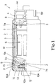
- a trochoid pump 1 is provided in a fuel tank as a fuel pump.
- a motor section M and a pump section P disposed at the other end side from the motor section M are mounted internally in a cylindrical housing 2 of the trochoid pump 1.
- the motor section M includes motor shaft 3 which is disposed coaxially with the housing 2.
- One end section of the shaft 3 is rotatably supported by a cover body 4, which is fixed so as to cover the one end side opening, at the above-described one end side opening of the housing 2.
- the other end of the motor shaft 3 is rotatably supported so that it can pass through a through-hole 5a in a partitioning plate 5 which is non-rotatably mounted on the inner circumferential surface of the housing 2.
- the partition plate 5 divides the motor section M from the pump section P.
- the other end of the motor shaft 3 extends toward the pump section P.
- An armature core 6, on which a coil is wound, is disposed integrally with the motor shaft 3, and a disk-shaped commutator 7 is fixed at and attached to the motor shaft 3 at one end side of the armature core 6.
- a plurality of commutator elements 7a are fixed at and attached to one end side of the commutator 7.
- a protruding end of a brush 8, which is disposed so as to protrude and retreat in the direction of the motor shaft 3 is set so that it can be resiliently brought into sliding contact with the cover body 4.
- an external lead-out terminal 8a for feeding power to the brush 8 is provided on the cover body 4, and a fuel discharge port 4a to be described later is arranged so as to communicate with the outside.
- a permanent magnet 9 that forms a magnetic field is fixed at and attached to the inner circumferential surface of the housing 2, wherein the motor shaft 3 is set so as to rotate integrally with the armature core 6 when power is fed to the commutator 7 via the brush 8.
- a rotor casing 10 that forms part of the pump section P acts as a cover body that covers the opening at the other end side of the housing 2.
- the casing 10 has a disk-shaped outer circumferential edge portion 10a that fits internally to the opening at the other end side of the housing 2, and is sealed relative to the housing 2 by caulking the housing 2 at the internally fitted position thereof.
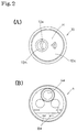
- a disk-shaped recessed groove section 10b is formed on the inner side (one end side) of the rotor casing 10.
- the groove center G of the recessed groove section 10b is formed so that it is offset from the circle center R of the rotor casing 10.
- a cam ring 11 is fixed integrally to the groove side face of the recessed groove section 10b so as to be internally fitted thereto, and a trochoid gear T is rotatably accommodated on the inner circumference of the cam ring 11.
- a bearing section 10d is formed so that it is recessed at the other end on the groove bottom face 10c of the recessed groove section 10b and is concentric with the circle center R of the rotor casing 10. The other end portion of the motor shaft 3 that protrudes from the partitioning plate 5 to the pump section P side is axially supported in the bearing portion 10d and abuts against it.
- a long curved hole-shaped suction port 10e is positioned at the right half section (corresponding to one half part of the invention) of the center line M, which is common to the center lines of the rotor casing 10 and the recessed groove section 10b in Fig. 3, and is formed at the groove bottom face 10c of the recessed groove part of the rotor casing 10.
- the suction port 10e is formed in the groove bottom face 10c as a through-hole and provides a communication between the inside and outside of the rotor casing 10. Fuel in the fuel tank can communicate with the inside of the trochoid pump 1 via the suction port 10e.
- a discharge port 10f recessed like a long curved hole is formed on the groove bottom face 10c that is located at the left half part (corresponding to the other half part of the pump) of the above-described center line M.
- a guide way 10g to the outer diametrical side of the cam ring 11 is recessed integrally with the outer diametrical side of the discharge port 10f.
- a funnel-shaped fuel guide body 10h is formed in the outer surface (the other end face) of the suction port 10e so as to protrude therefrom, in order to guide fuel to the rotor casing suction port 10e.
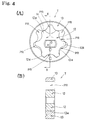
- a plurality of outer teeth 12a are formed on the outer periphery of the inner rotor 12 that constitutes the trochoid gear T.
- six teeth are formed around the circumference of the gear.
- the inner rotor 12 is accommodated in the recessed groove part 10b in such a way that the other end side thereof rotatably contacts the groove bottom face 10c of the rotor casing, and the other end part of the motor shaft 3, which protrudes to the pump section P side is fixed (like a key fitted into the key-hole) at the center of rotation so that it is prevented from turning.
- the inner rotor 12 can rotate integrally and concentrically with the motor shaft 3 centering around the circle center R of the rotor casing 10.
- a plurality of inner teeth 13a are formed on the inner periphery of the outer rotor 13. Seven teeth are formed around the circumference of the rotor 13 in the present embodiment.
- the outer rotor 13 is internally fitted to the recessed groove part 10b in such a way that the other end side thereof rotatably contacts the groove bottom part 10c, whereby the outer rotor 13 can rotate centering around the groove center G of the recessed groove part 10b that is biased from the motor shaft 3 (the inner rotor 12).
- the outer teeth 12a of the inner rotor 12 and the inner teeth 13a of the outer rotor 13 are engaged with each other at the lower half section in Fig. 3 and Fig. 4(A), whereby when the inner rotor 12 rotates, the outer rotor 13 rotates following the inner rotor 12.
- a sealing plate 14 that extends to the outer circumference of the outer rotor 13 is disposed at one end side of the inner and outer rotors 12 and 13 (Trochoid gear T), which are accommodated in the recessed groove part 10b, so that it abuts against the one end side thereof, wherein, by means of a spring 15 disposed between the sealing plate 14 and the partitioning plate 5, the trochoid gear T is urged towards the groove bottom face 10c of the rotor casing 10.
- six pump spaces PR both sides of which are enclosed by the groove bottom face 10c of the outer rotor and the sealing plate 14, are formed in the circumferential direction between the inner and outer teeth 12a and 13a.
- the arrangement is such that as the trochoid gear T rotates the respective pump spaces PR turn and move and their capacities vary gradually with respect to both of the sides.
- these pump spaces PR are set to vary so that the capacity of any one of the respective pump spaces PR is roughly zero (the minimum capacity state) when it is positioned at the lower end position in Fig. 4(A) and so that the capacity is a maximum when it is positioned at the upper end position.
- the trochoid gear T is designed so that it rotates in the counterclockwise direction in Fig. 4(A), whereby the right half section facing the drawing of the recessed groove part 10b is a pressure-reduced area where the capacity of the pump space PR gradually increases in line with rotations of the trochoid gear T.
- the left half section facing the drawing of the recessed groove part 10b is a highly pressurized area where the capacity of the pump space PR gradually decreases as the trochoid gear T rotates, whereby the trochoid gear T rotates while the respective pump spaces PR are discharging fuel through the discharge portions 10f, and the fuel capacity of the pump space PR is gradually decreased.
- the fuel discharged from the pump space PR is guided to the outer diametrical side at one end side (the partitioning plate 5 side) of the rotor casing 10 via the guide way 10g that communicates with the discharge portion 10f, and is caused to flow into the motor section M side via an opening 5b secured on the disk plate of the partitioning plate 5 like a through-hole.
- the fuel flowing in the motor section M side is discharged or supplied from the trochoid pump 1 to an engine (a target to which fuel is supplied) via a fuel discharge port 4a formed integrally with the cover body.
- FIG. 5(A) shows a state of maximum capacity, where any one of the pump spaces PR is located at the upper end part and the capacity of the pump space PR is maximized.
- the description is based on the assumption that the pump chamber which is in this state of maximum capacity is the first pump space PR1, and subsequent pump spaces are the second, third, fourth, fifth, sixth and seventh pump spaces, PR2, PR3, PR4, PR5, PR6 and PR7 in compliance with the direction of rotation.
- the suction port 10e faces the fifth and sixth pump spaces PR and is formed to have a size so that it is not faced to the first and fourth pump spaces PR1 and PR4, and the tip end edge part of the suction portion 10e in the direction of rotation of both rotors 12 and 13 extends between the sixth pump space PR6 and the first pump space PR1, and set to so as to open until the pump space PR reaches maximum capacity.
- the communication of the suction port 10e with an optional pump space PR is interrupted at a timing corresponding to that at which the capacity of the optional pump space PR is maximized, whereby the inside of the first pump space PR1 does not enter a pressure-reduced state.
- the discharge port 10f faces the second, third and fourth pump spaces PR2, PR3 and PR4.
- the rear side edge portion of the discharge port 10f in the direction of rotation is formed to a size that reaches the central portion of the second pump space PR2, whereby an optional pump space PR whose capacity is maximized is set so that the pump space PR communicates with the discharge port 10f, after elapse of an appointed period of time from the pump space PR commencing a reduction in capacity until the pump space facing the discharge port 10f before reaching the facing position of the second pump space PR2.
- the deaerating hole H is formed on the groove bottom face 10c of the rotor casing 10 so that it extends through to the outside. It is located at a position that is closed by the rear side edge of any one of the inner and outer teeth 12a and 13a of the inner and outer rotors 12 and 13 in the direction of rotation, which constitute the first pump space PR1 in the above-described state of maximum capacity.
- the deaerating hole H is small in diameter it is opened at a time when the trochoid gear T slightly rotates from the above-described state of maximum capacity. That is, it is set so that it can communicate with an optional pump space PR at a time at which the optional pump space PR, which has been in the state of maximum capacity, comes to reduce its capacity (See Fig. 5(B)).
- the deaerating hole H is formed at a position of the groove bottom face 10c that is closed by the vicinity of the contacting portions of the tooth tip of the inner tooth 13a with the tooth tip of the outer tooth 12a at the tip end side in the direction of rotation, which constitutes the pump space PR in the state of maximum capacity, that is to say the position that roughly corresponds to the outer diametrical end portion of the outer teeth 12a of the inner rotor.
- the deaerating hole H is located at the rear side of the discharge port 10f in the direction of rotation, and is formed in a state where an appointed interval is secured between the deaerating hole H and the discharge port 10f.
- the vaporized fuel is exhausted from the deaerating hole H.
- the deaerating hole H is caused to communicate with the pump space PR in a state where the pump space PR reaches a high-pressurized state in which the pump space PR reduces its capacity, the vaporized fuel is exhausted from the pump space PR in a state where it is subjected to pressure for attempting to reduce the capacity, wherein the exhausting performance of vaporized fuel from the deaerating hole H is set to be increased.
- the deaerating hole H is located on the rear side in the direction of rotation of the discharge port 10f that is formed at the high pressurized area being the left half section of the groove bottom face 10c, whereby an appointed interval is secured therebetween.
- the trochoid gear T rotates from the state of the maximum capacity as described above, and it rotates while maintaining a state of communication between only the pump space PR and deaerating hole H for an appointed period of time after the pump space PR communicates with the deaerating hole H.
- the pump space PR communicates with the discharge 10f (See Fig. 5(C)), wherein the exhaust through the deaerating hole H is suppressed.
- the deaerating hole H effectively carries out its exhausting function, wherein the vaporized air can be securely exhausted from the deaerating hole H.
- the trochoid pump 1 causes fuel in a fuel tank to flow into the pump spaces PR through the suction port 10e of the rotor casing 10 by rotations of the trochoid gear T in line with the rotations of the motor section M, and fuel in the pump spaces PR to be exhausted to the motor section M side through the discharge port 10f and the opening 5b of the partitioning plate 5, wherein the fuel is exhausted to the outside through the fuel exhaust port 4a that is formed at the cover body 4 of the trochoid pump 1, whereby the fuel is supplied by the trochoid pump 1.
- the suction port 10e faces an optional pump space PR until the optional pump space PR reaches the state of maximum capacity, whereby it is possible to prevent the inside of the pump space PR from entering a pressure-reduced state.
- the suction port 10e faces an optional pump space PR until the optional pump space PR reaches the state of maximum capacity, whereby it is possible to prevent the inside of the pump space PR from entering a pressure-reduced state.
- a selected interval exists between the discharge port 10f and the deaerating hole H and a state is secured for an appointed period of time, in which communication between the pump space PR and the deaerating hole H ensures to be continued.
- the deaerating hole H is caused to communicate with the pump space PR at a stage where a pump space that enters the state of maximum capacity commences reduction in its capacity as described above, there is no case where deaerating is forcibly carried out in a highly pressurized state, wherein, where the fuel temperature is normal, the amount of fuel that is discharged from the deaerating hole H can be decreased.
- Fig. 6 shows the results of having measured the amounts of discharge with respect to fuel temperatures, using the above-described prior art trochoid pump and a trochoid pump 1 on the basis of the above-described first embodiment.
- the ratio of lowering in the case of the trochoid pump according to the present embodiment can be made almost half the ratio of lowering in the case of the prior art trochoid pump.
- the lowering corresponds to that due to vaporization incidental to a temperature rise of the fuel in the case where the temperature is approx. 60°C, wherein it can be confirmed that the amount of discharge is not lowered on the basis of the trochoid pump 1 itself.
- the deaerating hole may be formed at any position that communicates with the pump space at a timing when the pump space in the state of maximum capacity commences reduction of its capacity.
- the deaerating hole may be formed at any point of portions along the circumference edge portion, on the rear side in the direction of rotation, of the inner and outer teeth of the inner and outer rotors at the tip end side in the direction of rotation, which constitute the pump space that has entered maximum capacity.
Landscapes
- Engineering & Computer Science (AREA)
- Mechanical Engineering (AREA)
- General Engineering & Computer Science (AREA)
- Rotary Pumps (AREA)
- Details And Applications Of Rotary Liquid Pumps (AREA)
- Details Of Reciprocating Pumps (AREA)
Abstract
Description
The invention will be described now by way of example only, with particular reference to the accompanying drawings. In the drawings:
Claims (3)
- A trochoid pump comprising;wherein, a deaerating hole is formed in said rotor casing to exhaust vaporized fuel in said pump spaces, said deaerating hole being located on the rear side of said discharge port in the rotor turning direction, and at a position where said deaerating hole is capable of communicating a pump space at a timing when a pump space, which is at its maximum capacity, commences decreasing its capacity.a trochoid gear having an inner rotor with outer teeth which engage inner teeth of an outer rotor, the number of teeth on the inner rotor being different from the number of teeth of the outer rotor, variable capacity pump spaces being formed between said teeth of said rotors as the rotation of the outer rotor follows rotation of the inner rotor; anda rotor casing against which one side surface of said trochoid gear is rotatably abutted, said casing having a suction port formed opposite to one half section at a region where the capacity of said pump spaces gradually increases, and a discharge port formed opposite to the other half section at a region where the capacity of the pump spaces gradually decreases;
- A trochoid pump as claimed in Claim 1, wherein said suction port formed in one half section of said rotor casing interrupts its communication with said pump space at a timing when the pump space enters its maximum capacity.
- A trochoid pump as claimed in Claim 1 or Claim 2, wherein said deaerating hole is positioned and formed at an outer diametrical portion of said inner rotor.
Applications Claiming Priority (2)
| Application Number | Priority Date | Filing Date | Title |
|---|---|---|---|
| JP2000392634 | 2000-12-25 | ||
| JP2000392634A JP2002195168A (en) | 2000-12-25 | 2000-12-25 | Trochoid pump |
Publications (2)
| Publication Number | Publication Date |
|---|---|
| EP1219835A2 true EP1219835A2 (en) | 2002-07-03 |
| EP1219835A3 EP1219835A3 (en) | 2003-10-15 |
Family
ID=18858589
Family Applications (1)
| Application Number | Title | Priority Date | Filing Date |
|---|---|---|---|
| EP01309877A Withdrawn EP1219835A3 (en) | 2000-12-25 | 2001-11-23 | Trochoid pump |
Country Status (4)
| Country | Link |
|---|---|
| EP (1) | EP1219835A3 (en) |
| JP (1) | JP2002195168A (en) |
| CN (1) | CN1361358A (en) |
| TW (1) | TW508412B (en) |
Cited By (1)
| Publication number | Priority date | Publication date | Assignee | Title |
|---|---|---|---|---|
| WO2006120138A1 (en) * | 2005-05-10 | 2006-11-16 | Siemens Vdo Automotive Ag | Internal gear fuel pump |
Families Citing this family (3)
| Publication number | Priority date | Publication date | Assignee | Title |
|---|---|---|---|---|
| JP4584770B2 (en) * | 2005-05-20 | 2010-11-24 | ペガサスミシン製造株式会社 | Sewing machine oiling equipment |
| JP4237731B2 (en) * | 2005-05-31 | 2009-03-11 | 株式会社日立製作所 | Motor-integrated internal gear pump, method for manufacturing the same, and electronic device |
| JP5692034B2 (en) * | 2011-12-14 | 2015-04-01 | 株式会社ダイヤメット | Oil pump rotor |
Family Cites Families (3)
| Publication number | Priority date | Publication date | Assignee | Title |
|---|---|---|---|---|
| US4697995A (en) * | 1982-07-29 | 1987-10-06 | Walbro Corporation | Rotary positive displacement fuel pump with purge port |
| JP3394544B2 (en) * | 1991-11-05 | 2003-04-07 | 株式会社デンソー | Gear pump |
| US5571003A (en) * | 1995-06-13 | 1996-11-05 | Walbro Corporation | Fuel pump with and method to modulate vapor purge port pressure pulses |
-
2000
- 2000-12-25 JP JP2000392634A patent/JP2002195168A/en active Pending
-
2001
- 2001-11-23 EP EP01309877A patent/EP1219835A3/en not_active Withdrawn
- 2001-11-29 TW TW90129501A patent/TW508412B/en not_active IP Right Cessation
- 2001-12-25 CN CN 01144019 patent/CN1361358A/en active Pending
Cited By (1)
| Publication number | Priority date | Publication date | Assignee | Title |
|---|---|---|---|---|
| WO2006120138A1 (en) * | 2005-05-10 | 2006-11-16 | Siemens Vdo Automotive Ag | Internal gear fuel pump |
Also Published As
| Publication number | Publication date |
|---|---|
| TW508412B (en) | 2002-11-01 |
| JP2002195168A (en) | 2002-07-10 |
| CN1361358A (en) | 2002-07-31 |
| EP1219835A3 (en) | 2003-10-15 |
Similar Documents
| Publication | Publication Date | Title |
|---|---|---|
| US5263818A (en) | Pump for pumping fluid without vacuum boiling | |
| US5122039A (en) | Electric-motor fuel pump | |
| US7314352B2 (en) | Electric pump | |
| US5810568A (en) | Rotary pump with a thermally conductive housing | |
| US20110135516A1 (en) | Electric pump | |
| JP2011190763A (en) | Rotary pump | |
| CN110500272B (en) | Electric pump | |
| JP5391016B2 (en) | Electric pump | |
| JP2013217223A (en) | Electric pump and method of manufacturing the same | |
| US20170229943A1 (en) | Electric compressor | |
| US20060245966A1 (en) | Rotor pump | |
| JPS59141762A (en) | Fuel pump | |
| JP3102522B2 (en) | Gear pump | |
| JP2002195168A (en) | Trochoid pump | |
| US20020131860A1 (en) | Fuel pump | |
| US11821422B2 (en) | Scroll compressor with a thin section in the orbiting volute wall | |
| KR20240056421A (en) | Scroll compressor | |
| JP2024124078A (en) | Scroll Compressor | |
| JPH08338340A (en) | Fuel pump with pressure pulse relaxation function of steam outlet and its relaxation method | |
| US20040228721A1 (en) | Fuel pump | |
| EP3708771B1 (en) | Pump device | |
| US20080226484A1 (en) | Internal gear pump | |
| JPS618485A (en) | Oil pump | |
| JPH0374565A (en) | Fuel pump device for automobile | |
| JP2005220817A (en) | Fuel pump |
Legal Events
| Date | Code | Title | Description |
|---|---|---|---|
| PUAI | Public reference made under article 153(3) epc to a published international application that has entered the european phase |
Free format text: ORIGINAL CODE: 0009012 |
|
| AK | Designated contracting states |
Kind code of ref document: A2 Designated state(s): AT BE CH CY DE DK ES FI FR GB GR IE IT LI LU MC NL PT SE TR |
|
| AX | Request for extension of the european patent |
Free format text: AL;LT;LV;MK;RO;SI |
|
| PUAL | Search report despatched |
Free format text: ORIGINAL CODE: 0009013 |
|
| AK | Designated contracting states |
Kind code of ref document: A3 Designated state(s): AT BE CH CY DE DK ES FI FR GB GR IE IT LI LU MC NL PT SE TR |
|
| AX | Request for extension of the european patent |
Extension state: AL LT LV MK RO SI |
|
| RIC1 | Information provided on ipc code assigned before grant |
Ipc: 7F 04C 11/00 B Ipc: 7F 04C 15/04 B Ipc: 7F 04C 2/10 A |
|
| AKX | Designation fees paid |
Designated state(s): FR IT |
|
| REG | Reference to a national code |
Ref country code: DE Ref legal event code: 8566 |
|
| STAA | Information on the status of an ep patent application or granted ep patent |
Free format text: STATUS: THE APPLICATION IS DEEMED TO BE WITHDRAWN |
|
| 18D | Application deemed to be withdrawn |
Effective date: 20040416 |