EP1219784A2 - Apparatus and method for localized cooling of gas turbine nozzle walls - Google Patents
Apparatus and method for localized cooling of gas turbine nozzle walls Download PDFInfo
- Publication number
- EP1219784A2 EP1219784A2 EP01308915A EP01308915A EP1219784A2 EP 1219784 A2 EP1219784 A2 EP 1219784A2 EP 01308915 A EP01308915 A EP 01308915A EP 01308915 A EP01308915 A EP 01308915A EP 1219784 A2 EP1219784 A2 EP 1219784A2
- Authority
- EP
- European Patent Office
- Prior art keywords
- vane
- cooling medium
- insert
- cooling
- impingement
- Prior art date
- Legal status (The legal status is an assumption and is not a legal conclusion. Google has not performed a legal analysis and makes no representation as to the accuracy of the status listed.)
- Granted
Links
- 238000001816 cooling Methods 0.000 title claims abstract description 109
- 238000000034 method Methods 0.000 title claims description 27
- 239000002826 coolant Substances 0.000 claims description 118
- 238000004891 communication Methods 0.000 claims description 8
- 230000003292 diminished effect Effects 0.000 description 2
- 238000010276 construction Methods 0.000 description 1
- 238000004519 manufacturing process Methods 0.000 description 1
- 239000000463 material Substances 0.000 description 1
- 239000007787 solid Substances 0.000 description 1
- 238000005728 strengthening Methods 0.000 description 1
Images


Classifications
-
- F—MECHANICAL ENGINEERING; LIGHTING; HEATING; WEAPONS; BLASTING
- F01—MACHINES OR ENGINES IN GENERAL; ENGINE PLANTS IN GENERAL; STEAM ENGINES
- F01D—NON-POSITIVE DISPLACEMENT MACHINES OR ENGINES, e.g. STEAM TURBINES
- F01D9/00—Stators
- F01D9/02—Nozzles; Nozzle boxes; Stator blades; Guide conduits, e.g. individual nozzles
-
- F—MECHANICAL ENGINEERING; LIGHTING; HEATING; WEAPONS; BLASTING
- F01—MACHINES OR ENGINES IN GENERAL; ENGINE PLANTS IN GENERAL; STEAM ENGINES
- F01D—NON-POSITIVE DISPLACEMENT MACHINES OR ENGINES, e.g. STEAM TURBINES
- F01D5/00—Blades; Blade-carrying members; Heating, heat-insulating, cooling or antivibration means on the blades or the members
- F01D5/12—Blades
- F01D5/14—Form or construction
- F01D5/18—Hollow blades, i.e. blades with cooling or heating channels or cavities; Heating, heat-insulating or cooling means on blades
- F01D5/187—Convection cooling
- F01D5/188—Convection cooling with an insert in the blade cavity to guide the cooling fluid, e.g. forming a separation wall
-
- F—MECHANICAL ENGINEERING; LIGHTING; HEATING; WEAPONS; BLASTING
- F01—MACHINES OR ENGINES IN GENERAL; ENGINE PLANTS IN GENERAL; STEAM ENGINES
- F01D—NON-POSITIVE DISPLACEMENT MACHINES OR ENGINES, e.g. STEAM TURBINES
- F01D25/00—Component parts, details, or accessories, not provided for in, or of interest apart from, other groups
- F01D25/08—Cooling; Heating; Heat-insulation
- F01D25/12—Cooling
-
- F—MECHANICAL ENGINEERING; LIGHTING; HEATING; WEAPONS; BLASTING
- F01—MACHINES OR ENGINES IN GENERAL; ENGINE PLANTS IN GENERAL; STEAM ENGINES
- F01D—NON-POSITIVE DISPLACEMENT MACHINES OR ENGINES, e.g. STEAM TURBINES
- F01D5/00—Blades; Blade-carrying members; Heating, heat-insulating, cooling or antivibration means on the blades or the members
- F01D5/12—Blades
- F01D5/14—Form or construction
- F01D5/18—Hollow blades, i.e. blades with cooling or heating channels or cavities; Heating, heat-insulating or cooling means on blades
- F01D5/187—Convection cooling
- F01D5/188—Convection cooling with an insert in the blade cavity to guide the cooling fluid, e.g. forming a separation wall
- F01D5/189—Convection cooling with an insert in the blade cavity to guide the cooling fluid, e.g. forming a separation wall the insert having a tubular cross-section, e.g. airfoil shape
-
- F—MECHANICAL ENGINEERING; LIGHTING; HEATING; WEAPONS; BLASTING
- F01—MACHINES OR ENGINES IN GENERAL; ENGINE PLANTS IN GENERAL; STEAM ENGINES
- F01D—NON-POSITIVE DISPLACEMENT MACHINES OR ENGINES, e.g. STEAM TURBINES
- F01D9/00—Stators
- F01D9/02—Nozzles; Nozzle boxes; Stator blades; Guide conduits, e.g. individual nozzles
- F01D9/04—Nozzles; Nozzle boxes; Stator blades; Guide conduits, e.g. individual nozzles forming ring or sector
-
- F—MECHANICAL ENGINEERING; LIGHTING; HEATING; WEAPONS; BLASTING
- F05—INDEXING SCHEMES RELATING TO ENGINES OR PUMPS IN VARIOUS SUBCLASSES OF CLASSES F01-F04
- F05D—INDEXING SCHEME FOR ASPECTS RELATING TO NON-POSITIVE-DISPLACEMENT MACHINES OR ENGINES, GAS-TURBINES OR JET-PROPULSION PLANTS
- F05D2240/00—Components
- F05D2240/10—Stators
- F05D2240/12—Fluid guiding means, e.g. vanes
- F05D2240/128—Nozzles
-
- F—MECHANICAL ENGINEERING; LIGHTING; HEATING; WEAPONS; BLASTING
- F05—INDEXING SCHEMES RELATING TO ENGINES OR PUMPS IN VARIOUS SUBCLASSES OF CLASSES F01-F04
- F05D—INDEXING SCHEME FOR ASPECTS RELATING TO NON-POSITIVE-DISPLACEMENT MACHINES OR ENGINES, GAS-TURBINES OR JET-PROPULSION PLANTS
- F05D2260/00—Function
- F05D2260/20—Heat transfer, e.g. cooling
- F05D2260/201—Heat transfer, e.g. cooling by impingement of a fluid
-
- F—MECHANICAL ENGINEERING; LIGHTING; HEATING; WEAPONS; BLASTING
- F05—INDEXING SCHEMES RELATING TO ENGINES OR PUMPS IN VARIOUS SUBCLASSES OF CLASSES F01-F04
- F05D—INDEXING SCHEME FOR ASPECTS RELATING TO NON-POSITIVE-DISPLACEMENT MACHINES OR ENGINES, GAS-TURBINES OR JET-PROPULSION PLANTS
- F05D2260/00—Function
- F05D2260/20—Heat transfer, e.g. cooling
- F05D2260/232—Heat transfer, e.g. cooling characterized by the cooling medium
- F05D2260/2322—Heat transfer, e.g. cooling characterized by the cooling medium steam
Definitions
- the present invention relates to a gas turbine having a closed-circuit cooling system for one or more nozzle stages and particularly relates to a gas turbine having closed-circuit cooling with localized cooling of nozzle wall portions.
- Gas turbine nozzles are often provided with open and/or closed-circuit cooling systems.
- an open system for example, an air-cooled nozzle
- compressor discharge air is typically supplied to the nozzle vane and exhausted into the hot gas stream.
- Local air-film cooling is provided to afford improved cooling in localized areas on the airfoil as necessary and desirable.
- closed-circuit nozzle cooling systems a cooling medium, e.g., steam, typically flows from the outer band through various cavities in the vane, through the inner band and returns via return passages through the cavities in the vane and outer band to a steam outlet. The steam cools the nozzle walls by impingement cooling.
- An example of a closed circuit steam-cooled nozzle for a gas turbine is disclosed in U.S. Patent No. 5,743,708, of common assignee herewith. That system also employs an open air cooling system for cooling the trailing edge of the vane.
- apparatus and methods for effectively cooling localized surfaces of the nozzle walls located adjacent the end of the closed cooling circuit to improve or increase low-cycle fatigue a portion of the cooling medium supplied at the beginning of the closed cooling circuit, i.e., a cooling medium portion at inlet conditions, is diverted to one or more secondary inserts within a cavity of the nozzle vane to cool the localized areas which are otherwise difficult to effectively cool at the end of the closed cooling circuit.
- a secondary insert having impingement openings is located within a nozzle cavity adjacent a localized area, i.e., a hot spot requiring localized cooling and is supplied with cooling medium, e.g., steam which has not yet picked up heat from the vane or lost any pressure.
- the secondary insert uses the pressure drop across the entire cooling circuit to drive the cooling medium through its impingement openings for impingement-cooling of the localized area. This improves the low-cycle fatigue in the localized area being impingement cooled because cooler steam is applied at a significantly higher pressure ratio resulting in substantial increased cooling than otherwise using essentially spent cooling steam at the end of the closed cooling circuit. It will be appreciated that the main insert in the vane cavity and, as illustrated in the prior above-identified U.S.
- the cooling medium e.g., steam
- the secondary insert is disposed adjacent a localized hot spot in lieu of impingement-cooling by the main insert at such localized area to supply cooler steam at a higher pressure ratio and, hence, more effectively cool such localized area.
- a gas turbine nozzle having inner and outer bands and a vane extending therebetween having at least one cavity between side walls of the vane, an insert within the cavity and extending from the outer band and along and spaced from one of the side walls of the vane terminating within the cavity short of one-half the length of the vane, the insert defining a passage for receiving a cooling medium and having openings through a wall thereof for flowing the cooling medium therethrough to impingement-cool the one side wall of the vane and a passage for exhausting spent impingement cooling medium from the vane cavity.
- a gas turbine having inner and outer bands and a vane extending therebetween having at least one cavity between side walls of the vane, a first insert within the one cavity for receiving a cooling medium, the insert having lateral walls spaced from the side walls and a plurality of openings therethrough for flowing a cooling medium through the openings to impingement-cool the side walls of the vane, and a second insert within the one cavity and having a lateral wall in spaced opposition to one of the side walls with a plurality of openings therethrough for flowing a cooling medium therethrough to impingement-cool a portion of the one side wall.
- a vane extending therebetween having at least one cavity between side walls of the vane and a closed circuit cooling system for flowing a cooling medium through the vane to cool the vane, a method of cooling a localized area along the vane wall comprising the steps of flowing a first portion of the cooling medium through a first insert in the one cavity for impingement cooling a first portion of the side walls of the vane; flowing a second portion of the cooling medium through a second insert in the one cavity for cooling the localized area of the vane wall, and supplying the second portion of the cooling medium to the second insert at a lower temperature than the temperature of the first portion of the cooling medium supplied to the first insert.
- a vane extending therebetween having at least one cavity between side walls of the vane and a closed circuit cooling system for flowing a cooling medium through the vane to cool the vane, a method of cooling a localized area along the vane wall comprising the steps of flowing a first portion of the cooling medium through a first insert in the one cavity for impingement cooling a first portion of the side walls of the vane; flowing a second portion of the cooling medium through a second insert in the one cavity for cooling the localized area of the vane wall, and including supplying the second portion of the cooling medium to the second insert at a higher pressure than the pressure of the first cooling medium portion supplied to the first insert.
- the present invention relates in particular to closed cooling circuits for nozzle stages of a turbine, preferably a first-stage nozzle, reference being made to the previously identified patent for disclosure of various other aspects of the turbine, its construction and methods of operation.
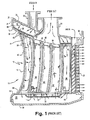
- a vane 10 comprising one of a plurality of circumferentially arranged segments 11 of a first-stage nozzle for a gas turbine. It will be appreciated that the segments 11 are connected one to the other to form an annular array of segments defining the hot gas path through the first-stage nozzle of the turbine.
- Each segment includes radially spaced outer and inner bands 12 and 14, respectively, with one or more of the nozzle vanes 10 extending between the outer and inner bands.
- each segment 11 may have two or more vanes. As illustrated, the vane 10 has a leading edge 18 and a trailing edge 20.
- the prior art cooling circuit for the illustrated first-stage nozzle vane segment of FIGURE 1 has a cooling steam inlet 22 to the outer band 12.
- a return steam outlet 24 also lies in communication with the nozzle segment.
- the outer band 12 includes an outer side railing 26, a leading railing 28, and a trailing railing 30 defining a plenum 32 with an upper cover 34 and an impingement plate 36 disposed in the outer band 12. (The terms outwardly and inwardly or outer and inner refer to a generally radial direction).
- Disposed between the impingement plate 36 and the inner wall 38 of outer band 12 are a plurality of structural ribs 40 extending between the side walls 26, forward wall 28 and trailing wall 30.
- the impingement plate 36 overlies the ribs 40 throughout the full extent of the plenum 32. Consequently, steam entering through inlet 22 into plenum 32 passes through the openings in the impingement plate 36 for impingement cooling of the outer wall 38 of the outer band 12, the outer band thus having first and second chambers 39 and 41 on opposite sides of the impingement plate.
- the first-stage nozzle vane 10 also has a plurality of cavities, for example, the leading edge cavity 42, an aft cavity 44, three intermediate return cavities 46, 48 and 50, and a trailing edge cavity 52. These cavities are defined by transversely extending ribs extending between opposite side walls of the vane. One or more additional cavities or fewer cavities may be provided.
- Leading edge cavity 42 and aft cavity 44 each have an insert, 54 and 56 respectively, while each of the intermediate cavities 46, 48 and 50 have similar inserts 58, 60 and 62, respectively, all such inserts being in the general form of hollow sleeves.
- the inserts may be shaped to correspond to the shape of the particular cavity in which the insert is to be provided.
- the side walls of the sleeves are provided with a plurality of impingement cooling openings, along portions of the insert which lie in opposition to the walls of the vane to be impingement cooled.
- the forward edge of the insert 54 is arcuate and the side walls would generally correspond in shape to the side walls of the cavity 42, all such walls of the insert having impingement openings.
- the side walls, only, of the insert sleeve 56 have impingement openings; the forward and aft walls of insert sleeve 56 being of a solid non-perforated material.
- inserts received in cavities 42, 44, 46, 48, and 50 are spaced from the walls of the cavities to enable a cooling medium, e.g., steam, to flow through the impingement openings to impact against the interior wall surfaces of the cavities, thus cooling the wall surfaces.
- a cooling medium e.g., steam
- the post-impingement cooling steam cooling the outer wall 38 flows into the open outer ends of inserts 54 and 56 for impingement-cooling of the vane walls in registration with the impingement openings in the inserts along the length of the vane.
- the steam then flows into a plenum 66 in the inner band 14 which is closed by an inner cover plate 68.
- Structural strengthening ribs 70 are integrally cast with the inner wall 69 of band 14. Radially inwardly of the ribs 70 is an impingement plate 72.
- the spent cooling steam flows by direction of the ribs 70 towards openings in ribs 70 (not shown in detail) for return flow through the cavities 46, 48, and 50 to the steam outlet 24.
- inserts 58, 60 and 62 are disposed in the cavities 46, 48, and 50 in spaced relation from the side walls and ribs defining the respective cavities.
- the impingement openings of inserts 58, 60 and 62 lie along the opposite sides thereof in registration with the vane walls.
- the spent cooling steam flows through the open inner ends of the inserts 58, 60 and 62 and through the impingement openings for impingement cooling the adjacent side walls of the vane.
- the spent cooling steam then flows out the outlet 24 for return to, e.g., the steam supply.
- the air cooling circuit of the trailing edge cavity of the combined steam and air cooling circuits of the vane illustrated in FIGURE 1 generally corresponds to the cooling circuit disclosed in the '708 patent. Therefore, a detailed discussion thereof is omitted.
- FIGURES 3 and 4 there is illustrated an improved closed cooling circuit, particularly for the second cavity 46, although the improved cooling circuit may be used for other cavities, cavity 46 being a representative example.
- the insert in cavity 46 is modified.
- Such modified insert constitutes a first or main insert in FIGURES 3, 4 and 6.
- Insert 80 similarly as insert 58 has opposite side walls with impingement openings 82 therethrough for impingement-cooling of the side walls of the vane adjacent the insert 80. Adjacent the outer band and on the convex side of the vane, however, the insert is stepped inwardly and has a wall 84 which does not contain impingement openings.
- the insert 80 which is closed at its outer end, provides impingement-cooling of the opposite walls of the vane except the wall portion adjacent the localized area 86, which does not receive impingement-cooling from the cooling steam flowing in insert 80.
- the impingement-cooling steam directed against the side walls of the vane exhausts from the cavity 46 through an exit chimney 88 and into the steam outlet 24.
- a secondary or second insert 90 is provided.
- This secondary insert 90 essentially constitutes a mini-insert in the form of a rectilinear pocket 92 having impingement openings 94 through one side face thereof.
- the secondary insert 90 extends only a very limited distance into vane 10, e.g., less than one-half the length of main insert 80 and terminates at its inner end short of the inner end of the main insert 80.
- the pocket 92 is essentially closed except for a steam inlet passage 96 opening adjacent its outer end.
- the secondary insert 90 is secured in a slot 98 (FIG. 3) formed in the flange 100 of the exit chimney 88.
- the outer end of the secondary insert 90 is brazed to the flange 100.
- the inlet passage 96 to the secondary insert 90 lies in communication with the outer or first chamber 39 of the outer band plenum 32. Consequently, cooling medium, e.g., steam, at inlet conditions is supplied the main insert 80 and the secondary insert 90 from a common source, i.e., plenum 32, the cooling medium supplied insert 90 being used to impingement-cool the localized area 86 on the convex side of the vane. Only a very minor portion of the inlet steam is supplied to the secondary insert 90 while the bulk of the inlet steam is supplied to the cooling circuit previously described with respect to FIGURE 1.
- cooling medium e.g., steam
- the spent impingement-cooling medium exiting the impingement openings 94 of the secondary insert 90 combines with the spent cooling medium exiting the openings 82 of the main insert 80 and combined therewith for flow through the exit chimney 88 and outlet 24.
- enhanced localized cooling is provided to an area of the vane otherwise ineffectively cooled, whereby improved low-cycle fatigue is obtained.
Landscapes
- Engineering & Computer Science (AREA)
- Mechanical Engineering (AREA)
- General Engineering & Computer Science (AREA)
- Turbine Rotor Nozzle Sealing (AREA)
Abstract
Description
- The present invention relates to a gas turbine having a closed-circuit cooling system for one or more nozzle stages and particularly relates to a gas turbine having closed-circuit cooling with localized cooling of nozzle wall portions.
- Gas turbine nozzles are often provided with open and/or closed-circuit cooling systems. In an open system, for example, an air-cooled nozzle, compressor discharge air is typically supplied to the nozzle vane and exhausted into the hot gas stream. Local air-film cooling is provided to afford improved cooling in localized areas on the airfoil as necessary and desirable. In closed-circuit nozzle cooling systems, a cooling medium, e.g., steam, typically flows from the outer band through various cavities in the vane, through the inner band and returns via return passages through the cavities in the vane and outer band to a steam outlet. The steam cools the nozzle walls by impingement cooling. An example of a closed circuit steam-cooled nozzle for a gas turbine is disclosed in U.S. Patent No. 5,743,708, of common assignee herewith. That system also employs an open air cooling system for cooling the trailing edge of the vane.
- In a closed circuit cooling system, however, it will be appreciated that toward the end of the closed cooling circuit, effective cooling of various surfaces is diminished. This is principally due to lower impingement pressure ratio and an increased cooling medium temperature along those local surfaces. For example, the walls of the cavities adjacent the cooling medium exhaust to the cooling medium outlet are difficult to effectively cool because they lie at the end of the cooling circuit. The cooling medium has gained significant heat pickup and the pressure ratio has been diminished sufficiently to render the localized impingement cooling less effective than desirable. As a consequence, the external wall temperature of the vane at such location is higher, leading to low-cycle fatigue life at such location. Accordingly, there is a need to effectively cool nozzle walls toward the end of the closed cooling circuit.
- In accordance with a preferred embodiment of the present invention, there is provided apparatus and methods for effectively cooling localized surfaces of the nozzle walls located adjacent the end of the closed cooling circuit to improve or increase low-cycle fatigue. To accomplish this, a portion of the cooling medium supplied at the beginning of the closed cooling circuit, i.e., a cooling medium portion at inlet conditions, is diverted to one or more secondary inserts within a cavity of the nozzle vane to cool the localized areas which are otherwise difficult to effectively cool at the end of the closed cooling circuit. Particularly, a secondary insert having impingement openings is located within a nozzle cavity adjacent a localized area, i.e., a hot spot requiring localized cooling and is supplied with cooling medium, e.g., steam which has not yet picked up heat from the vane or lost any pressure. The secondary insert uses the pressure drop across the entire cooling circuit to drive the cooling medium through its impingement openings for impingement-cooling of the localized area. This improves the low-cycle fatigue in the localized area being impingement cooled because cooler steam is applied at a significantly higher pressure ratio resulting in substantial increased cooling than otherwise using essentially spent cooling steam at the end of the closed cooling circuit. It will be appreciated that the main insert in the vane cavity and, as illustrated in the prior above-identified U.S. patent, receives the cooling medium, e.g., steam, from the inner band for flow through the insert for impingement-cooling of the vane walls adjacent the main insert. The secondary insert is disposed adjacent a localized hot spot in lieu of impingement-cooling by the main insert at such localized area to supply cooler steam at a higher pressure ratio and, hence, more effectively cool such localized area.
- In accordance with a preferred embodiment hereof, there is provided, in a gas turbine nozzle having inner and outer bands and a vane extending therebetween having at least one cavity between side walls of the vane, an insert within the cavity and extending from the outer band and along and spaced from one of the side walls of the vane terminating within the cavity short of one-half the length of the vane, the insert defining a passage for receiving a cooling medium and having openings through a wall thereof for flowing the cooling medium therethrough to impingement-cool the one side wall of the vane and a passage for exhausting spent impingement cooling medium from the vane cavity.
- In accordance with another preferred embodiment hereof, there is provided, in a gas turbine having inner and outer bands and a vane extending therebetween having at least one cavity between side walls of the vane, a first insert within the one cavity for receiving a cooling medium, the insert having lateral walls spaced from the side walls and a plurality of openings therethrough for flowing a cooling medium through the openings to impingement-cool the side walls of the vane, and a second insert within the one cavity and having a lateral wall in spaced opposition to one of the side walls with a plurality of openings therethrough for flowing a cooling medium therethrough to impingement-cool a portion of the one side wall.
- In a further preferred embodiment hereof, there is provided, in a gas turbine having inner and outer bands, a vane extending therebetween having at least one cavity between side walls of the vane and a closed circuit cooling system for flowing a cooling medium through the vane to cool the vane, a method of cooling a localized area along the vane wall comprising the steps of flowing a first portion of the cooling medium through a first insert in the one cavity for impingement cooling a first portion of the side walls of the vane; flowing a second portion of the cooling medium through a second insert in the one cavity for cooling the localized area of the vane wall, and supplying the second portion of the cooling medium to the second insert at a lower temperature than the temperature of the first portion of the cooling medium supplied to the first insert.
- In a still further preferred embodiment hereof, there is provided, in a gas turbine having inner and outer bands, a vane extending therebetween having at least one cavity between side walls of the vane and a closed circuit cooling system for flowing a cooling medium through the vane to cool the vane, a method of cooling a localized area along the vane wall comprising the steps of flowing a first portion of the cooling medium through a first insert in the one cavity for impingement cooling a first portion of the side walls of the vane; flowing a second portion of the cooling medium through a second insert in the one cavity for cooling the localized area of the vane wall, and including supplying the second portion of the cooling medium to the second insert at a higher pressure than the pressure of the first cooling medium portion supplied to the first insert.
- An embodiment of the invention will now be described, by way of example, with reference to the accompanying drawings, in which:
- FIGURE 1 is an enlarged cross-section of a first-stage nozzle vane as in the prior art;
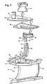
- FIGURE 2 is a perspective view of the nozzle segment of FIGURE 3 after fabrication and assembly;
- FIGURE 3 is an exploded perspective view of a nozzle segment with one vane illustrating an assemblage of main and secondary inserts an exit chimney, impingement plate, cover, and an exit port to the outer band portion of the segment in accordance with the present invention;
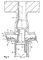
- FIGURE 4 is an enlarged fragmentary cross-sectional view illustrating the main and secondary inserts in the second cavity of the vane together with the exit chimney and portions of the outer band cooling system;
- FIGURE 5 is an exploded perspective view illustrating the nozzle exit chimney and secondary insert; and
- FIGURE 6 is a schematic view through the exit chimney of the vane illustrating the location of the main and secondary inserts.
-
- As discussed previously, the present invention relates in particular to closed cooling circuits for nozzle stages of a turbine, preferably a first-stage nozzle, reference being made to the previously identified patent for disclosure of various other aspects of the turbine, its construction and methods of operation. Referring now to Figure 1, there is schematically illustrated in cross-section a
vane 10 comprising one of a plurality of circumferentially arrangedsegments 11 of a first-stage nozzle for a gas turbine. It will be appreciated that thesegments 11 are connected one to the other to form an annular array of segments defining the hot gas path through the first-stage nozzle of the turbine. Each segment includes radially spaced outer andinner bands nozzle vanes 10 extending between the outer and inner bands. The segments are supported about the inner shell of the turbine (not shown) with adjoining segments being sealed one to the other. For purposes of this description, thevane 10 will be described as forming the sole vane of a segment, it being appreciated that eachsegment 11 may have two or more vanes. As illustrated, thevane 10 has a leadingedge 18 and atrailing edge 20. - The prior art cooling circuit for the illustrated first-stage nozzle vane segment of FIGURE 1 has a
cooling steam inlet 22 to theouter band 12. Areturn steam outlet 24 also lies in communication with the nozzle segment. Theouter band 12 includes anouter side railing 26, a leadingrailing 28, and a trailingrailing 30 defining aplenum 32 with anupper cover 34 and animpingement plate 36 disposed in theouter band 12. (The terms outwardly and inwardly or outer and inner refer to a generally radial direction). Disposed between theimpingement plate 36 and theinner wall 38 ofouter band 12 are a plurality ofstructural ribs 40 extending between theside walls 26,forward wall 28 andtrailing wall 30. Theimpingement plate 36 overlies theribs 40 throughout the full extent of theplenum 32. Consequently, steam entering throughinlet 22 intoplenum 32 passes through the openings in theimpingement plate 36 for impingement cooling of theouter wall 38 of theouter band 12, the outer band thus having first andsecond chambers - The first-
stage nozzle vane 10 also has a plurality of cavities, for example, the leadingedge cavity 42, anaft cavity 44, threeintermediate return cavities -
Leading edge cavity 42 andaft cavity 44 each have an insert, 54 and 56 respectively, while each of theintermediate cavities similar inserts edge cavity 42, the forward edge of theinsert 54 is arcuate and the side walls would generally correspond in shape to the side walls of thecavity 42, all such walls of the insert having impingement openings. The back side of the sleeve or insert 54 in opposition to therib 64 separatingcavity 42 fromcavity 46, however, does not have impingement openings. In theaft cavity 44, on the other hand, the side walls, only, of theinsert sleeve 56 have impingement openings; the forward and aft walls ofinsert sleeve 56 being of a solid non-perforated material. - It will be appreciated that the inserts received in
cavities inserts - As illustrated in FIGURE 1, the post-impingement cooling steam cooling the
outer wall 38 flows into the open outer ends ofinserts plenum 66 in theinner band 14 which is closed by aninner cover plate 68. Structural strengtheningribs 70 are integrally cast with theinner wall 69 ofband 14. Radially inwardly of theribs 70 is animpingement plate 72. As a consequence, it will be appreciated that the spent impingement cooling steam flowing fromcavities plenum 66 and through the impingement openings ofimpingement plate 72 for impingement cooling of theinner wall 69. The spent cooling steam flows by direction of theribs 70 towards openings in ribs 70 (not shown in detail) for return flow through thecavities steam outlet 24. Particularly,inserts cavities inserts inserts outlet 24 for return to, e.g., the steam supply. - The air cooling circuit of the trailing edge cavity of the combined steam and air cooling circuits of the vane illustrated in FIGURE 1 generally corresponds to the cooling circuit disclosed in the '708 patent. Therefore, a detailed discussion thereof is omitted.
- As noted above, in a closed-circuit nozzle designs, localized areas of the vane, particularly toward the end of the closed cooling circuit, may not be as effectively cooled as desired. As in the prior art of FIGURE 1, for example, a localized area adjacent the forward convex side wall of the vane is exposed to impingement-cooling using spent cooling steam adjacent the exit of the closed-circuit cooling system. The temperature differential of the spent cooling steam vis-a-vis the surfaces to be cooled is minimum and the pressure ratio driving the spent cooling steam through the impingement openings is likewise minimal. The present invention, however, affords improved localized cooling of surfaces at the end of the closed cooling system.
- Referring now to FIGURES 3 and 4, there is illustrated an improved closed cooling circuit, particularly for the
second cavity 46, although the improved cooling circuit may be used for other cavities,cavity 46 being a representative example. As illustrated, the insert incavity 46 is modified. Such modified insert constitutes a first or main insert in FIGURES 3, 4 and 6.Insert 80 similarly asinsert 58 has opposite side walls withimpingement openings 82 therethrough for impingement-cooling of the side walls of the vane adjacent theinsert 80. Adjacent the outer band and on the convex side of the vane, however, the insert is stepped inwardly and has awall 84 which does not contain impingement openings. As a consequence, and as best illustrated in FIGURE 4, theinsert 80, which is closed at its outer end, provides impingement-cooling of the opposite walls of the vane except the wall portion adjacent the localizedarea 86, which does not receive impingement-cooling from the cooling steam flowing ininsert 80. As illustrated in FIGURE 4, the impingement-cooling steam directed against the side walls of the vane exhausts from thecavity 46 through anexit chimney 88 and into thesteam outlet 24. - To effectively cool the
localized area 86 on the convex side of thevane 10, a secondary orsecond insert 90 is provided. Thissecondary insert 90 essentially constitutes a mini-insert in the form of arectilinear pocket 92 havingimpingement openings 94 through one side face thereof. Thesecondary insert 90 extends only a very limited distance intovane 10, e.g., less than one-half the length ofmain insert 80 and terminates at its inner end short of the inner end of themain insert 80. Thepocket 92 is essentially closed except for asteam inlet passage 96 opening adjacent its outer end. Thesecondary insert 90 is secured in a slot 98 (FIG. 3) formed in theflange 100 of theexit chimney 88. Preferably, the outer end of thesecondary insert 90 is brazed to theflange 100. As illustrated in FIGURE 4, theinlet passage 96 to thesecondary insert 90 lies in communication with the outer orfirst chamber 39 of theouter band plenum 32. Consequently, cooling medium, e.g., steam, at inlet conditions is supplied themain insert 80 and thesecondary insert 90 from a common source, i.e.,plenum 32, the cooling medium suppliedinsert 90 being used to impingement-cool thelocalized area 86 on the convex side of the vane. Only a very minor portion of the inlet steam is supplied to thesecondary insert 90 while the bulk of the inlet steam is supplied to the cooling circuit previously described with respect to FIGURE 1. The spent impingement-cooling medium exiting theimpingement openings 94 of thesecondary insert 90 combines with the spent cooling medium exiting theopenings 82 of themain insert 80 and combined therewith for flow through theexit chimney 88 andoutlet 24. As a consequence, enhanced localized cooling is provided to an area of the vane otherwise ineffectively cooled, whereby improved low-cycle fatigue is obtained. - For completeness, various aspects of the invention are set out in the following numbered clauses:
- 1. In a gas turbine nozzle having inner and outer bands (14, 12) and a vane (10) extending therebetween having at least one cavity (46) between side walls of the vane, an insert (90) within said cavity and extending from said outer band and along and spaced from one of the side walls of said vane terminating within said cavity short of one-half the length of the vane, said insert defining a passage (96) for receiving a cooling medium and having openings (94) through a wall thereof for flowing the cooling medium therethrough to impingement-cool said one side wall of said vane and a passage for exhausting spent impingement cooling medium from the vane cavity.
- 2. Apparatus according to Clause 1, wherein said outer band includes a plenum (32) for receiving the cooling medium, said insert lying in communication with said plenum.
- 3. Apparatus according to
Clause 2, wherein said outer band includes an impingement plate (36) in said plenum spaced from a wall of said outer band forming part of a hot gas path through the turbine, said impingement plate dividing the plenum into first and second chambers (39, 41) on opposite sides thereof and having a plurality of openings therethrough for flowing the cooling medium from said first chamber through said openings into said second chamber for impingement cooling said outer band wall, said insert lying in communication with said first chamber for receiving a portion of the cooling medium from said first chamber. - 4. Apparatus according to Clause 1, wherein said one side wall is a convex side wall of the vane.
- 5. In a gas turbine having inner and outer bands (14, 12) and a vane (10) extending therebetween having at least one cavity (46) between side walls of the vane, a first insert (80) within said one cavity for receiving a cooling medium, said insert having lateral walls spaced from said side walls and a plurality of openings (82) therethrough for flowing a cooling medium through said openings to impingement-cool the side walls of the vane, and a second insert (90) within said one cavity and having a lateral wall in spaced opposition to one of said side walls with a plurality of openings (94) therethrough for flowing a cooling medium therethrough to impingement-cool a portion of said one side wall.
- 6. Apparatus according to Clause 5, wherein said second insert extends from adjacent said outer band into said vane a distance short of an inner end of said first insert.
- 7. Apparatus according to Clause 5, wherein said first insert extends substantially the full length of said vane.
- 8. Apparatus according to Clause 5, wherein said second insert extends a distance in said vane less than one-half the length of said vane between said inner and outer bands.
- 9. Apparatus according to Clause 5, wherein said outer band (12) includes a plenum (30) for receiving the cooling medium, said second insert lying in communication with said plenum.
- 10. Apparatus according to Clause 9, wherein said outer band includes an impingement plate (36) in said plenum spaced from a wall of said outer band forming part of a hot gas path through the turbine, said impingement plate dividing the plenum into first and second chambers (39, 41) on opposite sides thereof and having a plurality of openings therethrough for flowing the cooling medium from said first chamber through said openings into said second chamber to impingement-cool said outer band wall, said second insert lying in communication with said first chamber for receiving a portion of the cooling medium from said first chamber.
- 11. In a gas turbine having inner and outer bands (14, 12), a vane (10)
extending therebetween having at least one cavity (46) between side walls of
the vane and a closed circuit cooling system for flowing a cooling medium
through said vane to cool the vane, a method of cooling a localized area
along the vane wall comprising the steps of:
- flowing a first portion of the cooling medium through a first insert (80) in the one cavity for impingement cooling a first portion of the side walls of the vane;
- flowing a second portion of the cooling medium through a second insert (90) in said one cavity for cooling the localized area of the vane wall, and
- supplying the second portion of the cooling medium to said second insert at a lower temperature than the temperature of the first portion of the cooling medium supplied to said first insert.
- 12. A method according to
Clause 11, including supplying the first and second portions of the cooling medium from a common source (32), passing the first portion of the cooling medium from said common source through said vane in one direction for cooling the vane and subsequently passing the first portion of the cooling medium into said first insert through said vane in a generally opposite direction to cool said vane. - 13. A method according to
Clause 12, including passing the second portion of the cooling medium from said common source directly into said second insert. - 14. A method according to
Clause 11, including providing a plenum (32) for the cooling medium in said outer band, passing the first portion of the cooling medium from the plenum in a generally radial inward direction through said vane for cooling the vane and into a plenum in said inner band, subsequently passing the first portion of the cooling medium from the plenum in the inner band into said first insert for flow in a generally radial outward direction to cool said vane and passing the second portion of the cooling medium from the plenum in said outer band into said second insert. - 15. A method according to
Clause 14, including combining spent first and second portions of the cooling medium for flow to a spent cooling medium outlet in said outer band. - 16. A method according to
Clause 11, including forming a plurality of cavities (42, 44, 46, 48, 50) in said vane, providing another insert (54) in another of said cavities, providing a plenum (32) for the cooling medium in said outer band, passing the first portion of the cooling medium from the plenum in a generally radial inward direction through said another insert for impingement cooling of another portion of the side walls of said vane and into a plenum (66) in said inner band (14), subsequently passing the first portion of the cooling medium from the plenum in the inner band into said first insert (80) for flow in a generally radial outward direction for impingement cooling of said side walls of said vane, passing the second portion of the cooling medium from the plenum in said outer band into said second insert (90), and combining spent first and second portions of the cooling medium for flow to a spent cooling medium outlet in said outer band. - 17. A method according to
Clause 11, including supplying the second portion of the cooling medium to said second insert at a higher pressure than the pressure of the first cooling medium portion supplied to said first insert. - 18. In a gas turbine having inner and outer bands (14, 12), a vane (10)
extending therebetween having at least one cavity (46) between side walls of
the vane and a closed circuit cooling system for flowing a cooling medium
through said vane to cool the vane, a method of cooling a localized area (86)
along the vane wall comprising the steps of:
- flowing a first portion of the cooling medium through a first insert (80) in the one cavity (46) for impingement cooling a first portion of the side walls of the vane;
- flowing a second portion of the cooling medium through a second insert (90) in said one cavity for cooling the localized area of the vane wall; and
- supplying the second portion of the cooling medium to said second insert at a higher pressure than the pressure of the first cooling medium portion supplied to said first insert.
- 19. A method according to
Clause 18, including supplying the first and second portions of the cooling medium from a common source (32), passing the first portion of the cooling medium from said common source through said vane in one direction for cooling the vane and subsequently passing the first portion of the cooling medium into said first insert through said vane in a generally opposite direction to cool said vane. - 20. A method according to Clause 19, including passing the second portion of the cooling medium from said common source directly into said second insert.
- 21. A method according to
Clause 18, including providing a plenum (32) for the cooling medium in said outer band, passing the first portion of the cooling medium from the plenum in a generally radial inward direction through said vane for cooling the vane and into a plenum (66) in said inner band, subsequently passing the first portion of the cooling medium from the plenum in the inner band into said first insert for flow in a generally radial outward direction to cool said vane and passing the second portion of the cooling medium from the plenum in said outer band into said second insert. - 22. A method according to Clause 21, including combining spent first and second portions of the cooling medium for flow to a spent cooling medium outlet in said outer band.
- 23. A method according to
Clause 18, including forming a plurality of cavities (42, 44, 46, 48, 50) in said vane, providing another insert (54) in another of said cavities, providing a plenum (32) for the cooling medium in said outer band, passing the first portion of the cooling medium from the plenum in a generally radial inward direction through said another insert for impingement cooling of another portion of the side walls of said vane and into a plenum (66) in said inner band (14), subsequently passing the first portion of the cooling medium from the plenum in the inner band into said first insert for flow in a generally radial outward direction for impingement cooling of said side walls of said vane, passing the second portion of the cooling medium from the plenum in said outer band into said second insert (90), and combining spent first and second portions of the cooling medium for flow to a spent cooling medium outlet in said outer band. - 24. A method according to Clause 23, including supplying the second portion of the cooling medium to said second insert at a higher pressure than the pressure of the first cooling medium portion supplied to said first insert.
-
Claims (10)
- A gas turbine nozzle including inner and outer bands (14, 12) and a vane (10) extending therebetween having at least one cavity (46) between side walls of the vane, and an insert (90) within said cavity and extending from said outer band and along and spaced from one of the side walls of said vane terminating within said cavity short of one-half the length of the vane, said insert defining a passage (96) for receiving a cooling medium and having openings (94) through a wall thereof for flowing the cooling medium therethrough to impingement-cool said one side wall of said vane and a passage for exhausting spent impingement cooling medium from the vane cavity.
- A gas turbine nozzle according to Claim 1, wherein said outer band includes a plenum (32) for receiving the cooling medium, said insert lying in communication with said plenum.
- A gas turbine nozzle according to Claim 2, wherein said outer band includes an impingement plate (36) in said plenum spaced from a wall of said outer band forming part of a hot gas path through the turbine, said impingement plate dividing the plenum into first and second chambers (39, 41) on opposite sides thereof and having a plurality of openings therethrough for flowing the cooling medium from said first chamber through said openings into said second chamber for impingement cooling said outer band wall, said insert lying in communication with said first chamber for receiving a portion of the cooling medium from said first chamber.
- A gas turbine nozzle including inner and outer bands (14, 12) and a vane (10) extending therebetween having at least one cavity (46) between side walls of the vane, a first insert (80) within said one cavity for receiving a cooling medium, said insert having lateral walls spaced from said side walls and a plurality of openings (82) therethrough for flowing a cooling medium through said openings to impingement-cool the side walls of the vane, and a second insert (90) within said one cavity and having a lateral wall in spaced opposition to one of said side walls with a plurality of openings (94) therethrough for flowing a cooling medium therethrough to impingement-cool a portion of said one side wall.
- A method of cooling a localized area along the vane wall a gas turbine having inner and outer bands (14, 12), a vane (10) extending therebetween having at least one cavity (46) between side walls of the vane and a closed circuit cooling system for flowing a cooling medium through said vane to cool the vane, the method comprising the steps of:flowing a first portion of the cooling medium through a first insert (80) in the one cavity for impingement cooling a first portion of the side walls of the vane;flowing a second portion of the cooling medium through a second insert (90) in said one cavity for cooling the localized area of the vane wall, andsupplying the second portion of the cooling medium to said second insert at a lower temperature than the temperature of the first portion of the cooling medium supplied to said first insert.
- A method according to Claim 5, including supplying the first and second portions of the cooling medium from a common source (32), passing the first portion of the cooling medium from said common source through said vane in one direction for cooling the vane and subsequently passing the first portion of the cooling medium into said first insert through said vane in a generally opposite direction to cool said vane.
- A method according to Claim 6, including passing the second portion of the cooling medium from said common source directly into said second insert.
- A method according to Claim 5, including providing a plenum (32) for the cooling medium in said outer band, passing the first portion of the cooling medium from the plenum in a generally radial inward direction through said vane for cooling the vane and into a plenum in said inner band, subsequently passing the first portion of the cooling medium from the plenum in the inner band into said first insert for flow in a generally radial outward direction to cool said vane and passing the second portion of the cooling medium from the plenum in said outer band into said second insert.
- A method according to Claim 8, including combining spent first and second portions of the cooling medium for flow to a spent cooling medium outlet in said outer band.
- A method of cooling a localized area (86) along the vane wall a gas turbine having inner and outer bands (14, 12), a vane (10) extending therebetween having at least one cavity (46) between side walls of the vane and a closed circuit cooling system for flowing a cooling medium through said vane to cool the vane, the method comprising the steps of:flowing a first portion of the cooling medium through a first insert (80) in the one cavity (46) for impingement cooling a first portion of the side walls of the vane;flowing a second portion of the cooling medium through a second insert (90) in said one cavity for cooling the localized area of the vane wall; andsupplying the second portion of the cooling medium to said second insert at a higher pressure than the pressure of the first cooling medium portion supplied to said first insert.
Applications Claiming Priority (2)
| Application Number | Priority Date | Filing Date | Title |
|---|---|---|---|
| US749616 | 1985-06-27 | ||
| US09/749,616 US6543993B2 (en) | 2000-12-28 | 2000-12-28 | Apparatus and methods for localized cooling of gas turbine nozzle walls |
Publications (3)
| Publication Number | Publication Date |
|---|---|
| EP1219784A2 true EP1219784A2 (en) | 2002-07-03 |
| EP1219784A3 EP1219784A3 (en) | 2004-03-31 |
| EP1219784B1 EP1219784B1 (en) | 2007-01-17 |
Family
ID=25014488
Family Applications (1)
| Application Number | Title | Priority Date | Filing Date |
|---|---|---|---|
| EP01308915A Expired - Lifetime EP1219784B1 (en) | 2000-12-28 | 2001-10-19 | Apparatus and method for localized cooling of gas turbine nozzle walls |
Country Status (7)
| Country | Link |
|---|---|
| US (1) | US6543993B2 (en) |
| EP (1) | EP1219784B1 (en) |
| JP (1) | JP4130540B2 (en) |
| KR (1) | KR100671573B1 (en) |
| AT (1) | ATE351969T1 (en) |
| CZ (1) | CZ20013699A3 (en) |
| DE (1) | DE60126051T2 (en) |
Cited By (5)
| Publication number | Priority date | Publication date | Assignee | Title |
|---|---|---|---|---|
| EP1380725A3 (en) * | 2002-07-12 | 2004-09-15 | AVIO S.p.A. | Method of producing and assembling a cooling device inside an axial-flow gas turbine blade, and blade produced using such a method |
| EP1655451A1 (en) * | 2004-11-09 | 2006-05-10 | Rolls-Royce Plc | A cooling arrangement |
| EP1674660A3 (en) * | 2004-12-21 | 2009-09-09 | United Technologies Corporation | Impingement cooled turbine components with dirt separation |
| EP3184750A1 (en) * | 2015-12-21 | 2017-06-28 | United Technologies Corporation | Impingement cooling baffle |
| EP3527783A1 (en) * | 2018-01-31 | 2019-08-21 | United Technologies Corporation | Vane flow diverter |
Families Citing this family (23)
| Publication number | Priority date | Publication date | Assignee | Title |
|---|---|---|---|---|
| US6843637B1 (en) | 2003-08-04 | 2005-01-18 | General Electric Company | Cooling circuit within a turbine nozzle and method of cooling a turbine nozzle |
| US20090220331A1 (en) * | 2008-02-29 | 2009-09-03 | General Electric Company | Turbine nozzle with integral impingement blanket |
| US8397516B2 (en) * | 2009-10-01 | 2013-03-19 | General Electric Company | Apparatus and method for removing heat from a gas turbine |
| US8840370B2 (en) | 2011-11-04 | 2014-09-23 | General Electric Company | Bucket assembly for turbine system |
| US9845691B2 (en) | 2012-04-27 | 2017-12-19 | General Electric Company | Turbine nozzle outer band and airfoil cooling apparatus |
| US9670797B2 (en) | 2012-09-28 | 2017-06-06 | United Technologies Corporation | Modulated turbine vane cooling |
| US10436445B2 (en) | 2013-03-18 | 2019-10-08 | General Electric Company | Assembly for controlling clearance between a liner and stationary nozzle within a gas turbine |
| US9322556B2 (en) | 2013-03-18 | 2016-04-26 | General Electric Company | Flow sleeve assembly for a combustion module of a gas turbine combustor |
| US9316155B2 (en) | 2013-03-18 | 2016-04-19 | General Electric Company | System for providing fuel to a combustor |
| US9631812B2 (en) | 2013-03-18 | 2017-04-25 | General Electric Company | Support frame and method for assembly of a combustion module of a gas turbine |
| US9316396B2 (en) | 2013-03-18 | 2016-04-19 | General Electric Company | Hot gas path duct for a combustor of a gas turbine |
| US9383104B2 (en) | 2013-03-18 | 2016-07-05 | General Electric Company | Continuous combustion liner for a combustor of a gas turbine |
| US9400114B2 (en) | 2013-03-18 | 2016-07-26 | General Electric Company | Combustor support assembly for mounting a combustion module of a gas turbine |
| US9360217B2 (en) | 2013-03-18 | 2016-06-07 | General Electric Company | Flow sleeve for a combustion module of a gas turbine |
| US9879554B2 (en) * | 2015-01-09 | 2018-01-30 | Solar Turbines Incorporated | Crimped insert for improved turbine vane internal cooling |
| US10012092B2 (en) * | 2015-08-12 | 2018-07-03 | United Technologies Corporation | Low turn loss baffle flow diverter |
| US20170198602A1 (en) * | 2016-01-11 | 2017-07-13 | General Electric Company | Gas turbine engine with a cooled nozzle segment |
| US10450880B2 (en) * | 2016-08-04 | 2019-10-22 | United Technologies Corporation | Air metering baffle assembly |
| US11702941B2 (en) * | 2018-11-09 | 2023-07-18 | Raytheon Technologies Corporation | Airfoil with baffle having flange ring affixed to platform |
| US10711620B1 (en) * | 2019-01-14 | 2020-07-14 | General Electric Company | Insert system for an airfoil and method of installing same |
| US10975709B1 (en) * | 2019-11-11 | 2021-04-13 | Rolls-Royce Plc | Turbine vane assembly with ceramic matrix composite components and sliding support |
| US11371709B2 (en) | 2020-06-30 | 2022-06-28 | General Electric Company | Combustor air flow path |
| CN115950914B (en) * | 2023-01-10 | 2023-07-14 | 哈尔滨工程大学 | A Modeling Method of Measuring Device for Gas Turbine Combustor Wall Surface Cooling Characteristics |
Citations (1)
| Publication number | Priority date | Publication date | Assignee | Title |
|---|---|---|---|---|
| US5743708A (en) | 1994-08-23 | 1998-04-28 | General Electric Co. | Turbine stator vane segments having combined air and steam cooling circuits |
Family Cites Families (7)
| Publication number | Priority date | Publication date | Assignee | Title |
|---|---|---|---|---|
| CA586665A (en) * | 1959-11-10 | A. Petrie James | Blading for turbines or compressors | |
| GB753224A (en) * | 1953-04-13 | 1956-07-18 | Rolls Royce | Improvements in or relating to blading for turbines or compressors |
| BE755567A (en) * | 1969-12-01 | 1971-02-15 | Gen Electric | FIXED VANE STRUCTURE, FOR GAS TURBINE ENGINE AND ASSOCIATED TEMPERATURE ADJUSTMENT ARRANGEMENT |
| JPS61149503A (en) * | 1984-12-24 | 1986-07-08 | Toshiba Corp | Turbine blade |
| JPS62228603A (en) * | 1986-03-31 | 1987-10-07 | Toshiba Corp | Gas turbine blade |
| US4798515A (en) * | 1986-05-19 | 1989-01-17 | The United States Of America As Represented By The Secretary Of The Air Force | Variable nozzle area turbine vane cooling |
| US6325593B1 (en) * | 2000-02-18 | 2001-12-04 | General Electric Company | Ceramic turbine airfoils with cooled trailing edge blocks |
-
2000
- 2000-12-28 US US09/749,616 patent/US6543993B2/en not_active Expired - Fee Related
-
2001
- 2001-10-12 CZ CZ20013699A patent/CZ20013699A3/en unknown
- 2001-10-19 DE DE60126051T patent/DE60126051T2/en not_active Expired - Lifetime
- 2001-10-19 EP EP01308915A patent/EP1219784B1/en not_active Expired - Lifetime
- 2001-10-19 AT AT01308915T patent/ATE351969T1/en not_active IP Right Cessation
- 2001-10-26 JP JP2001328576A patent/JP4130540B2/en not_active Expired - Fee Related
- 2001-10-26 KR KR1020010066192A patent/KR100671573B1/en not_active Expired - Fee Related
Patent Citations (1)
| Publication number | Priority date | Publication date | Assignee | Title |
|---|---|---|---|---|
| US5743708A (en) | 1994-08-23 | 1998-04-28 | General Electric Co. | Turbine stator vane segments having combined air and steam cooling circuits |
Cited By (7)
| Publication number | Priority date | Publication date | Assignee | Title |
|---|---|---|---|---|
| EP1380725A3 (en) * | 2002-07-12 | 2004-09-15 | AVIO S.p.A. | Method of producing and assembling a cooling device inside an axial-flow gas turbine blade, and blade produced using such a method |
| EP1655451A1 (en) * | 2004-11-09 | 2006-05-10 | Rolls-Royce Plc | A cooling arrangement |
| US7507071B2 (en) | 2004-11-09 | 2009-03-24 | Rolls-Royce Plc | Cooling arrangement |
| EP1674660A3 (en) * | 2004-12-21 | 2009-09-09 | United Technologies Corporation | Impingement cooled turbine components with dirt separation |
| EP3184750A1 (en) * | 2015-12-21 | 2017-06-28 | United Technologies Corporation | Impingement cooling baffle |
| US10781715B2 (en) | 2015-12-21 | 2020-09-22 | Raytheon Technologies Corporation | Impingement cooling baffle |
| EP3527783A1 (en) * | 2018-01-31 | 2019-08-21 | United Technologies Corporation | Vane flow diverter |
Also Published As
| Publication number | Publication date |
|---|---|
| ATE351969T1 (en) | 2007-02-15 |
| EP1219784B1 (en) | 2007-01-17 |
| DE60126051D1 (en) | 2007-03-08 |
| US6543993B2 (en) | 2003-04-08 |
| EP1219784A3 (en) | 2004-03-31 |
| JP4130540B2 (en) | 2008-08-06 |
| KR100671573B1 (en) | 2007-01-18 |
| CZ20013699A3 (en) | 2003-01-15 |
| DE60126051T2 (en) | 2007-11-15 |
| KR20020055359A (en) | 2002-07-08 |
| US20020085910A1 (en) | 2002-07-04 |
| JP2002201911A (en) | 2002-07-19 |
Similar Documents
| Publication | Publication Date | Title |
|---|---|---|
| EP1219784B1 (en) | Apparatus and method for localized cooling of gas turbine nozzle walls | |
| KR100534812B1 (en) | A turbine stator vane segment having internal cooling circuits | |
| EP1160418B1 (en) | Turbine vane segment | |
| EP0791127B1 (en) | Gas turbine vane with a cooled inner shroud | |
| EP1149983A2 (en) | Film cooling for a closed loop cooled airfoil | |
| US6435814B1 (en) | Film cooling air pocket in a closed loop cooled airfoil | |
| US6468031B1 (en) | Nozzle cavity impingement/area reduction insert | |
| EP0698724B1 (en) | Cooling circuit for turbine stator vane trailing edge | |
| US5591002A (en) | Closed or open air cooling circuits for nozzle segments with wheelspace purge | |
| EP0698723A2 (en) | Turbine stator vane segment having closed cooling circuit | |
| EP0690205A2 (en) | Cooling apparatus for turbine shrouds | |
| US6416275B1 (en) | Recessed impingement insert metering plate for gas turbine nozzles | |
| JP4393667B2 (en) | Cooling circuit for steam / air cooled turbine nozzle stage | |
| CA2205042C (en) | Gas turbine vane with a cooled inner shroud |
Legal Events
| Date | Code | Title | Description |
|---|---|---|---|
| PUAI | Public reference made under article 153(3) epc to a published international application that has entered the european phase |
Free format text: ORIGINAL CODE: 0009012 |
|
| AK | Designated contracting states |
Kind code of ref document: A2 Designated state(s): AT BE CH CY DE DK ES FI FR GB GR IE IT LI LU MC NL PT SE TR |
|
| AX | Request for extension of the european patent |
Free format text: AL;LT;LV;MK;RO;SI |
|
| RIC1 | Information provided on ipc code assigned before grant |
Ipc: 7F 01D 5/18 A |
|
| PUAL | Search report despatched |
Free format text: ORIGINAL CODE: 0009013 |
|
| AK | Designated contracting states |
Kind code of ref document: A3 Designated state(s): AT BE CH CY DE DK ES FI FR GB GR IE IT LI LU MC NL PT SE TR |
|
| AX | Request for extension of the european patent |
Extension state: AL LT LV MK RO SI |
|
| 17P | Request for examination filed |
Effective date: 20040930 |
|
| AKX | Designation fees paid |
Designated state(s): AT BE CH CY DE DK ES FI FR GB GR IE IT LI LU MC NL PT SE TR |
|
| 17Q | First examination report despatched |
Effective date: 20050204 |
|
| GRAP | Despatch of communication of intention to grant a patent |
Free format text: ORIGINAL CODE: EPIDOSNIGR1 |
|
| GRAS | Grant fee paid |
Free format text: ORIGINAL CODE: EPIDOSNIGR3 |
|
| GRAA | (expected) grant |
Free format text: ORIGINAL CODE: 0009210 |
|
| AK | Designated contracting states |
Kind code of ref document: B1 Designated state(s): AT BE CH CY DE DK ES FI FR GB GR IE IT LI LU MC NL PT SE TR |
|
| PG25 | Lapsed in a contracting state [announced via postgrant information from national office to epo] |
Ref country code: DK Free format text: LAPSE BECAUSE OF FAILURE TO SUBMIT A TRANSLATION OF THE DESCRIPTION OR TO PAY THE FEE WITHIN THE PRESCRIBED TIME-LIMIT Effective date: 20070117 Ref country code: AT Free format text: LAPSE BECAUSE OF FAILURE TO SUBMIT A TRANSLATION OF THE DESCRIPTION OR TO PAY THE FEE WITHIN THE PRESCRIBED TIME-LIMIT Effective date: 20070117 Ref country code: FI Free format text: LAPSE BECAUSE OF FAILURE TO SUBMIT A TRANSLATION OF THE DESCRIPTION OR TO PAY THE FEE WITHIN THE PRESCRIBED TIME-LIMIT Effective date: 20070117 |
|
| REG | Reference to a national code |
Ref country code: GB Ref legal event code: FG4D |
|
| REG | Reference to a national code |
Ref country code: CH Ref legal event code: EP Ref country code: CH Ref legal event code: NV Representative=s name: SERVOPATENT GMBH |
|
| REG | Reference to a national code |
Ref country code: IE Ref legal event code: FG4D |
|
| REF | Corresponds to: |
Ref document number: 60126051 Country of ref document: DE Date of ref document: 20070308 Kind code of ref document: P |
|
| PG25 | Lapsed in a contracting state [announced via postgrant information from national office to epo] |
Ref country code: ES Free format text: LAPSE BECAUSE OF FAILURE TO SUBMIT A TRANSLATION OF THE DESCRIPTION OR TO PAY THE FEE WITHIN THE PRESCRIBED TIME-LIMIT Effective date: 20070428 |
|
| REG | Reference to a national code |
Ref country code: SE Ref legal event code: TRGR |
|
| ET | Fr: translation filed | ||
| PG25 | Lapsed in a contracting state [announced via postgrant information from national office to epo] |
Ref country code: PT Free format text: LAPSE BECAUSE OF FAILURE TO SUBMIT A TRANSLATION OF THE DESCRIPTION OR TO PAY THE FEE WITHIN THE PRESCRIBED TIME-LIMIT Effective date: 20070618 |
|
| PLBE | No opposition filed within time limit |
Free format text: ORIGINAL CODE: 0009261 |
|
| STAA | Information on the status of an ep patent application or granted ep patent |
Free format text: STATUS: NO OPPOSITION FILED WITHIN TIME LIMIT |
|
| 26N | No opposition filed |
Effective date: 20071018 |
|
| PG25 | Lapsed in a contracting state [announced via postgrant information from national office to epo] |
Ref country code: BE Free format text: LAPSE BECAUSE OF FAILURE TO SUBMIT A TRANSLATION OF THE DESCRIPTION OR TO PAY THE FEE WITHIN THE PRESCRIBED TIME-LIMIT Effective date: 20070117 |
|
| REG | Reference to a national code |
Ref country code: CH Ref legal event code: PFA Owner name: GENERAL ELECTRIC COMPANY Free format text: GENERAL ELECTRIC COMPANY#1 RIVER ROAD#SCHENECTADY, NY 12345 (US) -TRANSFER TO- GENERAL ELECTRIC COMPANY#1 RIVER ROAD#SCHENECTADY, NY 12345 (US) |
|
| PG25 | Lapsed in a contracting state [announced via postgrant information from national office to epo] |
Ref country code: GR Free format text: LAPSE BECAUSE OF FAILURE TO SUBMIT A TRANSLATION OF THE DESCRIPTION OR TO PAY THE FEE WITHIN THE PRESCRIBED TIME-LIMIT Effective date: 20070418 |
|
| PG25 | Lapsed in a contracting state [announced via postgrant information from national office to epo] |
Ref country code: MC Free format text: LAPSE BECAUSE OF NON-PAYMENT OF DUE FEES Effective date: 20071031 |
|
| PG25 | Lapsed in a contracting state [announced via postgrant information from national office to epo] |
Ref country code: IE Free format text: LAPSE BECAUSE OF NON-PAYMENT OF DUE FEES Effective date: 20071019 |
|
| PG25 | Lapsed in a contracting state [announced via postgrant information from national office to epo] |
Ref country code: CY Free format text: LAPSE BECAUSE OF FAILURE TO SUBMIT A TRANSLATION OF THE DESCRIPTION OR TO PAY THE FEE WITHIN THE PRESCRIBED TIME-LIMIT Effective date: 20070117 |
|
| PG25 | Lapsed in a contracting state [announced via postgrant information from national office to epo] |
Ref country code: LU Free format text: LAPSE BECAUSE OF NON-PAYMENT OF DUE FEES Effective date: 20071019 |
|
| PG25 | Lapsed in a contracting state [announced via postgrant information from national office to epo] |
Ref country code: TR Free format text: LAPSE BECAUSE OF FAILURE TO SUBMIT A TRANSLATION OF THE DESCRIPTION OR TO PAY THE FEE WITHIN THE PRESCRIBED TIME-LIMIT Effective date: 20070117 |
|
| PGFP | Annual fee paid to national office [announced via postgrant information from national office to epo] |
Ref country code: CH Payment date: 20131029 Year of fee payment: 13 Ref country code: SE Payment date: 20131029 Year of fee payment: 13 Ref country code: FR Payment date: 20131017 Year of fee payment: 13 Ref country code: GB Payment date: 20131028 Year of fee payment: 13 Ref country code: DE Payment date: 20131029 Year of fee payment: 13 |
|
| PGFP | Annual fee paid to national office [announced via postgrant information from national office to epo] |
Ref country code: IT Payment date: 20131024 Year of fee payment: 13 Ref country code: NL Payment date: 20131026 Year of fee payment: 13 |
|
| REG | Reference to a national code |
Ref country code: DE Ref legal event code: R119 Ref document number: 60126051 Country of ref document: DE |
|
| REG | Reference to a national code |
Ref country code: NL Ref legal event code: V1 Effective date: 20150501 |
|
| REG | Reference to a national code |
Ref country code: CH Ref legal event code: PL |
|
| REG | Reference to a national code |
Ref country code: SE Ref legal event code: EUG |
|
| GBPC | Gb: european patent ceased through non-payment of renewal fee |
Effective date: 20141019 |
|
| PG25 | Lapsed in a contracting state [announced via postgrant information from national office to epo] |
Ref country code: DE Free format text: LAPSE BECAUSE OF NON-PAYMENT OF DUE FEES Effective date: 20150501 Ref country code: SE Free format text: LAPSE BECAUSE OF NON-PAYMENT OF DUE FEES Effective date: 20141020 Ref country code: GB Free format text: LAPSE BECAUSE OF NON-PAYMENT OF DUE FEES Effective date: 20141019 Ref country code: LI Free format text: LAPSE BECAUSE OF NON-PAYMENT OF DUE FEES Effective date: 20141031 Ref country code: CH Free format text: LAPSE BECAUSE OF NON-PAYMENT OF DUE FEES Effective date: 20141031 |
|
| REG | Reference to a national code |
Ref country code: FR Ref legal event code: ST Effective date: 20150630 |
|
| PG25 | Lapsed in a contracting state [announced via postgrant information from national office to epo] |
Ref country code: FR Free format text: LAPSE BECAUSE OF NON-PAYMENT OF DUE FEES Effective date: 20141031 Ref country code: IT Free format text: LAPSE BECAUSE OF NON-PAYMENT OF DUE FEES Effective date: 20141019 Ref country code: NL Free format text: LAPSE BECAUSE OF NON-PAYMENT OF DUE FEES Effective date: 20150501 |